FTA (изд-во). Flexography: Principles And Practices. Vol.1-6
Подождите немного. Документ загружается.


PRESSES AND PRESS EQUIPMENT 73
Web Viewers
F
rom the beginning of flexographic
printing, press manufacturers
have constantly made improve-
ments in their designs and
process techniques to reach high-
er optimum printing speeds for
improved profitability. As web speeds
increased, many process functions became
more critical, requiring greater operator
attention and skill to obtain maximum effi-
ciency, quality assurance and waste control.
As a result, web viewers were developed and
made available to aid the press operator in
fully utilizing the press potential.
As web speeds exceeded the 250 to 300
feet per minute (fpm) range, above which
operators could no longer accurately inspect
the printed web, web scanners became a
necessity for quality assurance. Today, with
the increased demand for more sophisticated
print requirements, the selection of a suitable
web viewer is of prime importance.
The degree of efficiency obtainable is
greatly dependent upon the ability of the web
viewer to provide a stable image of such
quality that precise definition of detail, regis-
tration, etc., is readily visible at all printing
speeds. When this stable image is accom-
plished, the operator can constantly monitor
the print quality and make the necessary
press adjustments, as well as observe the
adjustment results, while the press is running
at optimum web speeds. This, of course, min-
imizes material waste and press downtime.
STROBOSCOPE
The simplest web-viewing device is a strobo-
scope, similar to an automotive timing light.
This device consists of a lamp and voltage
pulse source, providing a brief instant flash
with a frequency synchronous with the print
repeat length. Being relatively simple in con-
cept and structure, it is the least expensive
option but has severe limitations as a suitable
web viewer.
With a stroboscope, the viewing area is lim-
ited to the size of the lamp beam diameter,
which varies with distances, of course. The
distance also controls the degree of illumina-
tion and definition of print detail. Discounting
operator discomfort and fatigue, image defini-
tion is also less than satisfactory. The lamp of
the stroboscope is designed to flash in syn-
chronization with the print repeat length, or
multiples thereof, so that an identical portion
of the web is constantly viewed. Therefore,
frequency is dependent upon print repeat
length versus web speed and will vary as
either or both are changed.
At low speeds, the operator observes a brief
instant flash, lacking the necessary dwell time
to retain the image between flashes. As web
speed increases, a frequency is reached where
persistence of vision bridges the gap between
flashes, providing the stroboscopic effect, or
a stationary image. As the frequency
approaches and exceeds approximately 25
cycles per second, the stationary effect is lost
and the stroboscope begins to provide a con-
stant illumination typical to the common light
bulb. With these factors in mind, it is readily
apparent that a web viewer with the strobo-
scopic concept is limited in performance.
OSCILLATING MIRROR
Another type of web scanner is a device
74 FLEXOGRAPHY: PRINCIPLES & PRACTICES
4!
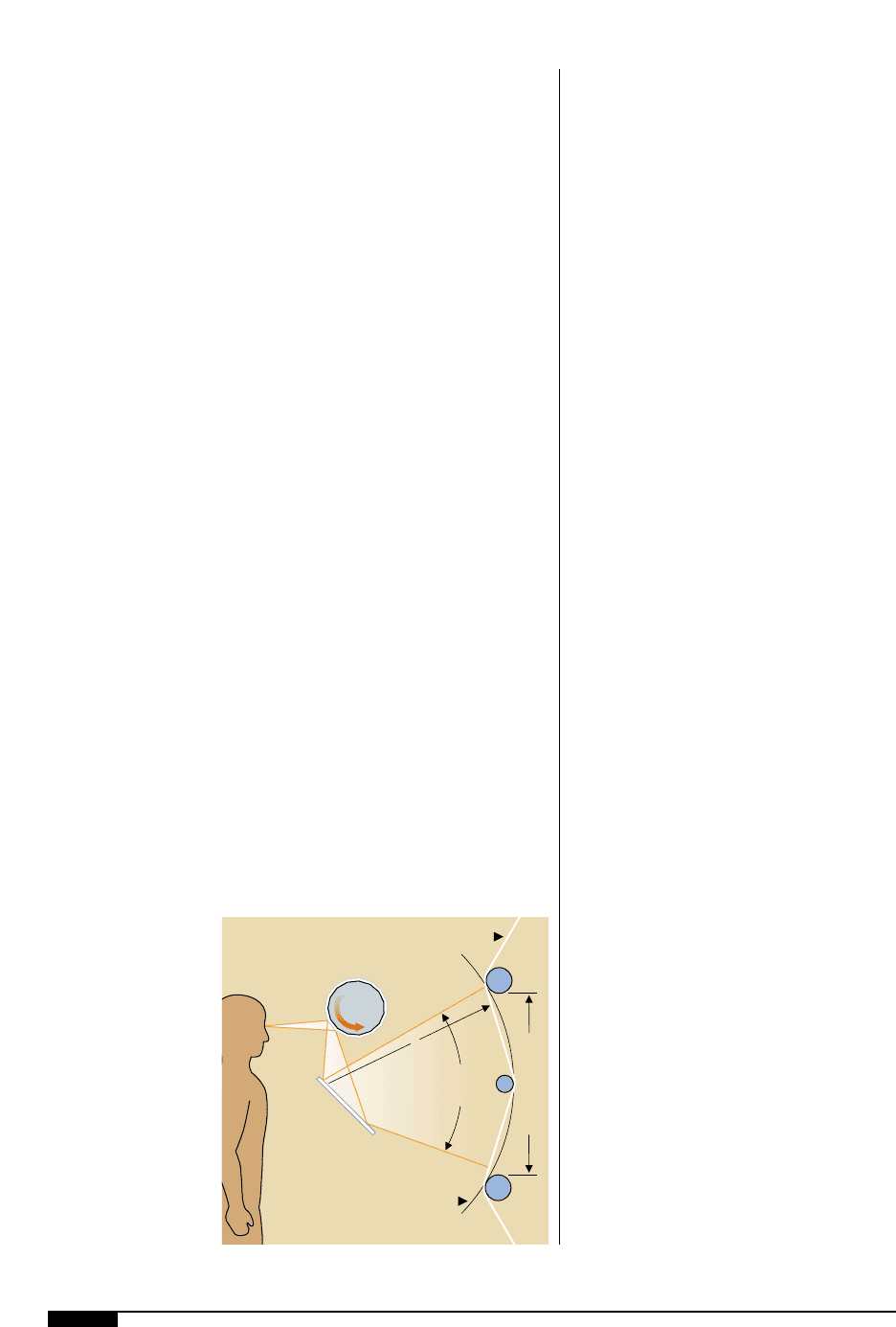
By “bending” the
printed web over an
idler roller to simulate
an arc throughout the
sweeping angle, the
“bent-web” viewing
feature eliminates
the sweeping angle
distortion during a
straight-web threading
orientation.
consisting of a rectangular mirror oscillating
in synchronization with the print repeat
length. In practice, the web viewer is mount-
ed at a fixed distance from the web plane
and the sweeping angle of the oscillating
mirror is varied to accommodate the various
print repeat lengths, or multiples thereof.
The oscillating mirror is generally sized to
view a web width of 18" to 20" and can be
mounted on side-motion tracks to traverse
web widths beyond its fixed viewing range.
Due to the width and height restrictions of
the oscillating mirror, only a portion of the
print repeat length is visible through the
viewing area at a given time. As a result, the
synchronous drive is equipped with a modu-
lator so that the oscillating frequency can be
regulated to cause the field of vision to drift
through the entire print repeat length. Any
portion of the print repeat length can be con-
stantly viewed by simply reestablishing syn-
chronization.
This type of web viewer has a definite
advantage over the stroboscope concept.
Auxiliary light fixtures constantly illuminate
the web, rather than utilizing the flashing
lamp, which eliminates the flickering effect
and reduces operator fatigue. In addition,
the visual dwell time is increased due to the
angular movement of the oscillating mirror
throughout the oscillating cycle, improving
Rotating Mirror
Drum
Fixed
Viewing
Angle
Visual Dwell Span
X
Strip
Mirror
Bent Web
True Arc
4!
the operator’s ability to define print detail.
The prime disadvantages for the oscillating
mirror concept are its speed limitations and
lack of image stability. Any mechanical
device that utilizes reciprocating motion,
regardless of its design quality, has many
moving parts that are subject to speed limita-
tions and rapid deterioration of precision fit-
ting or surface wear. Since the oscillating fre-
quency, or reciprocating motion, increases
with speed and is further magnified as small-
er repeat lengths are viewed, this concept is
limited to viewing web repeats of moderate
length (6"–12") and slower-moving webs.
For printing applications within the suited
speed range of 100 to 300 fpm, there is anoth-
er disadvantage that induces image instabili-
ty and distortion. This problem is caused by
the constant variation in optical distance
between the flat web and oscillating mirror
surface, as it sweeps through its angular
movement. Obviously, the occurrence rela-
tive to oscillation frequency provides an
additional need for the inspector to continu-
ally refocus on the image each time a print
repeat length is viewed.
ROTATING DRUM MIRRORS
Figure
4!
illustrates a third generation of
web viewing equipment. This method uses a
rotating drum of mirrors to offset the speed
limitations inherent in the previously dis-
cussed web viewers.
The multisided drum of mirrors is rotated
in synchronization with the viewed web seg-
ment of a given print repeat length. Each
time a viewed web segment passes through
the visual dwell span, one mirror of the
rotating drum reflects the image until the
next mirror picks up the identical area of the
succeeding print repeat length. This process
is repeated continuously as other mirrors
rotate into position in synchronization with
the print repeat. The series of images is then
reflected to a separate strip mirror that is

PRESSES AND PRESS EQUIPMENT 75
cam-operated from the drum shaft, provid-
ing tracking through the visual dwell span.
The rotary drum web viewer generally has
a fixed viewing width of 18" to 20". The basic
viewer is normally mounted on an overhead
track assembly with a sideways motion fea-
ture for traversing the total web width as
required by the specific press design. Since
the viewing angle of the rotary drum viewer is
fixed, the track assembly must also have pro-
visions for positioning the web viewer at var-
ious distances from the web. This capability
allows the rotary drum position relative to the
web to vary so that the visual dwell span is
equal to the print repeat length being viewed.
“Bent-Web” Feature
Also shown in Figure
4!
is the “bent-web”
viewing feature. This feature was developed
to eliminate the optical distance change that
occurs as the viewed web segment sweeps
though the visual dwell span when utilizing a
straight-web threading orientation. The
printed web is “bent” over an idler roller to
provide the similarity of an arc throughout
the sweeping angle. Although not a true arc,
optical distance is relatively constant
throughout the visual dwell span. This fea-
ture practically eliminates the sweeping
angle distortion, providing image stability.
Relative to reciprocating motion, the “bent-
web” technique reduces the transition of the
cam profile enough that the strip mirror
oscillation is practically zero. In operation,
this technique, when combined with a rotat-
ing drum mirror concept, can provide suit-
able web scanning at speeds up to 2,000 fpm.
The “bent” idler located in the visual dwell
span optically disappears at speeds over 250
to 300 fpm. The optical disappearance in the
field of view is relative to the idler size.
Therefore, idler diameters should be kept to
3" or less. Concentricity and balance of the
bent idler are of prime importance to pre-
vent web flutter and image instability.
Automatic Synchronization
The synchronous rotation of the mirror
drum is achieved with two self-synchronizing
motors. One self-synchronizing motor on the
drive assembly, acting as a transmitter, is
coupled to the print cylinder shaft or any
other line shaft that has a ratio equivalent to
one revolution of the print cylinder circum-
ference. This self-synchronizing motor trans-
mits voltage to the second self-synchronizing
motor in the basic web-viewing unit driving
the drum of mirrors. Synchronization is now
achieved since one print repeat length equals
one mirror movement of the drum rotation.
By disrupting the synchronization phase
manually with a hand-wheel, or automatical-
ly by a built-in electric drive, the viewed web
segment can be varied throughout the entire
print repeat length. This provides the opera-
tor with the ability to slowly scan any portion
of the print repeat length.
Lighting and Magnification
Suitable front light fixtures are required to
provide constant illumination of the printed
surface of the web. Fixtures should be posi-
tioned and properly baffled to avoid obstruc-
tion or glare throughout the viewing area. For
applications where transparent or translu-
cent materials are frequently printed, it is
advantageous to utilize a rear lighting fixture
for improved web illumination.
Due to the image stability of a rotating
device, scopes are available for print magnifi-
cation. In the range of five to ten power, criti-
cal inspection of minute details of fine type,
texture and other quality details is feasible.
VIDEO SCANNING
In recent years, coinciding with the evolu-
tion to higher speeds, wider web widths,
longer repeats, gravure-like quality, in-
creased, number of colors and more on-
press coating, the need for better visual
inspection has become critical. Video scan-
76 FLEXOGRAPHY: PRINCIPLES & PRACTICES
ning and video web inspection systems have
filled this need, and are now the most popu-
lar form of online print inspection methods.
They are available from basic viewing sys-
tems to automated defect detection systems.
This discussion will focus primarily on basic
viewing systems.
System Configuration
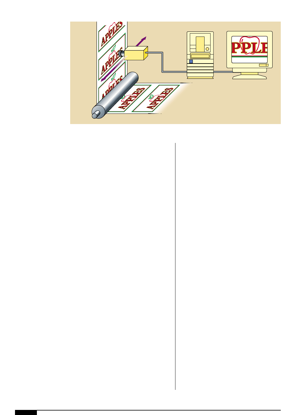
A typical video inspection system is
shown in Figure
4@
and consists of these
four basic components:
• camera assembly
• camera positioning assembly
• CPU and software
• press timing devices
Camera Assembly. Typically, the camera
assembly contains a high resolution RGB
(red, green, blue) color camera. A motorized
zoom lens and diopter, or close-up lens,
together determine the overall magnification
of the system. The zoom lens also controls
the focus and iris. The iris controls the
amount of light reflected into the camera and
hence the brightness of the image. A strobe
lighting system uses a xenon flash lamp that
produces a high-intensity short-duration
flash of light. This illuminates and provides
stop-motion of the area for the camera to
capture the image.
4@
A typical video
inspection system
consists of a camera
assembly, camera
positioning assembly,
CPU and software, and
press timing devices.
Camera-Positioner Assembly. This is typically
available in three different configurations:
manual, motorized and programmable. If a
manual positioner is chosen, the positioner
must be installed on the press so the opera-
tor has physical access to move the camera
across the web (crossweb). Manual position-
ers are primarily used on narrow-web
machines. Motorized positioners provide
basic left-right jog capability. Programmable
positioners offer multiple, user-programma-
ble positions to be stored and then activated
in a continuous loop.
The camera positioner needs to be installed
after the last line operation that requires
inspection. This is typically accomplished
after the dryer, but before the last dancer
assembly prior to rewind. Most inspection
system suppliers do not supply the brackets
that connect the positioner to the press frame
as standard equipment. Many will provide
these at an additional charge. The brackets
and the chosen viewing area are critical to
ensuring satisfactory viewing results.
The chosen viewing area must meet some
minimal requirements. The distance from the
web surface to the camera/lens is defined by
the camera lens focal length. The focal length
determines the height at which the camera
positioner assembly is positioned above the
web viewing area. This dimension should be
MonitorCPU
Video
Camera
Traverse System
Web
4@
PRESSES AND PRESS EQUIPMENT 77
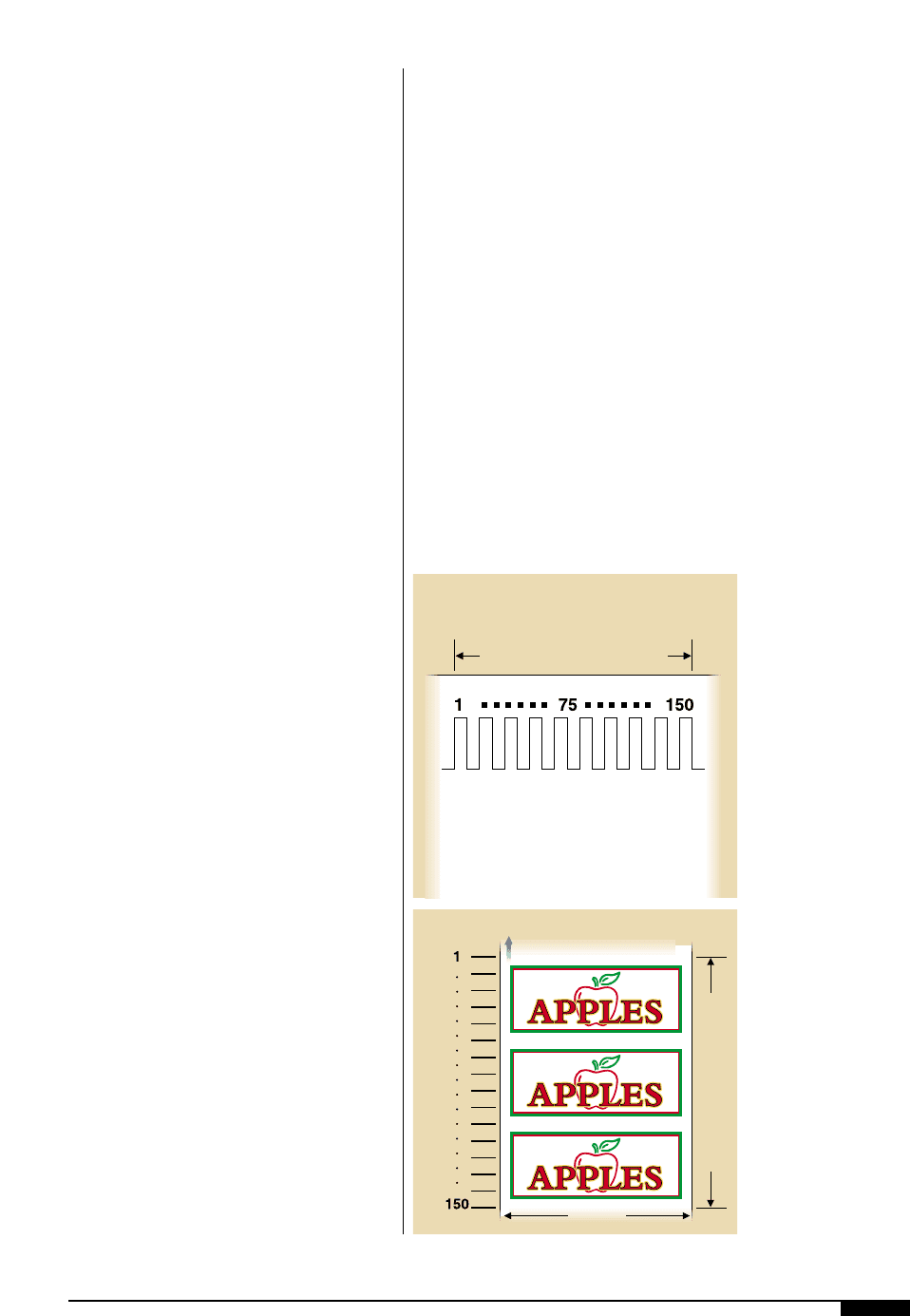
The video system uses a short-duration,
xenon strobe light to illuminate the cam-
era’s viewing area. This short-duration
strobe flash causes the web material to
appear stationary while the camera cap-
tures an image. The signal input device pro-
vides a timing signal so that the operator
can control the point at which the strobe
fires (Figure
4#
). The timing signal is
directly related to the print cylinder cir-
cumference, which, in effect, divides the
print repeat into sections as illustrated in
Figure
4$
. The timing signal provides the
ability to advance or retard the point on the
web, in the machine direction, where the
strobe will flash. When used in conjunction
with the camera’s crossweb-positioning
capability, any area on the printed repeat
held from sideframe to sideframe to ensure
that the viewed image remains in focus from
one web edge to the other.
The web should be supported so that web-
plane change is kept to a minimum. This may
be accomplished by utilizing two idler rolls
that are relatively close together. Another
method would be to install the camera posi-
tioner assembly as close as possible to one
idler roll that has approximately 90° of wrap,
taking care that the camera viewing area
does not extend beyond the curvature of the
idler roll. If the web is allowed to experience
excessive plane change, the viewed image
may not remain in focus. Care should also be
taken to ensure the centerline of the camera
can be positioned over the web edge and that
no interference is caused by the sideframes.
When properly installed, the camera-posi-
tioner assembly will provide complete cross-
web viewing capability.
CPU and Software. The CPU (central pro-
cessing unit) contains the main computer
system and its associated power supplies.
Also contained in the CPU is the frame
grabber, which “grabs” the image that is
captured by the camera and converts it to a
form that can be displayed on a high-reso-
lution video monitor for inspection. The
software gives the computer the instruc-
tions to follow. These include the basic
instructions for capturing and displaying
images and any advanced instructions such
as automatic color monitoring, register
monitoring or bar-code verification.
Signal Input Device. The signal input device
is used to provide the inspection system
with speed and timing information. There
are many different types of signal input
devices. The most commonly used sensors
include proximity sensors, optical encoders
and print mark sensors. The one to choose
will depend on the specific application.
Regardless of which one is used, the instal-
lation of this device is crucial for optimum
system performance.
One Print Cylinder Circumference
One Print Cylinder Circumference
Crossweb
Machine Direction
4#
4$
4#
The signal input
device provides a
timing signal so that
the operator can control
the point at which the
strobe fires directly
related to the print
cylinder circumference.
4$
Each mark in the timing
signal represents a
standard number of
strobe pulses. Thus, the
opertor porgrams the
strobe to pulse at a rate
that will allow it to view
the appropriate portion
of the web.
length can be viewed.
As an example, in Figure
4$
each mark in
the machine direction represents 10 timing
pulses. In order to view the center area of
the web, the camera-positioner would be
moved crossweb to the center of the web
and the timing pulse would be set to fire the
strobe at pulse 75, since there are a total of
150 pulses per repeat length.
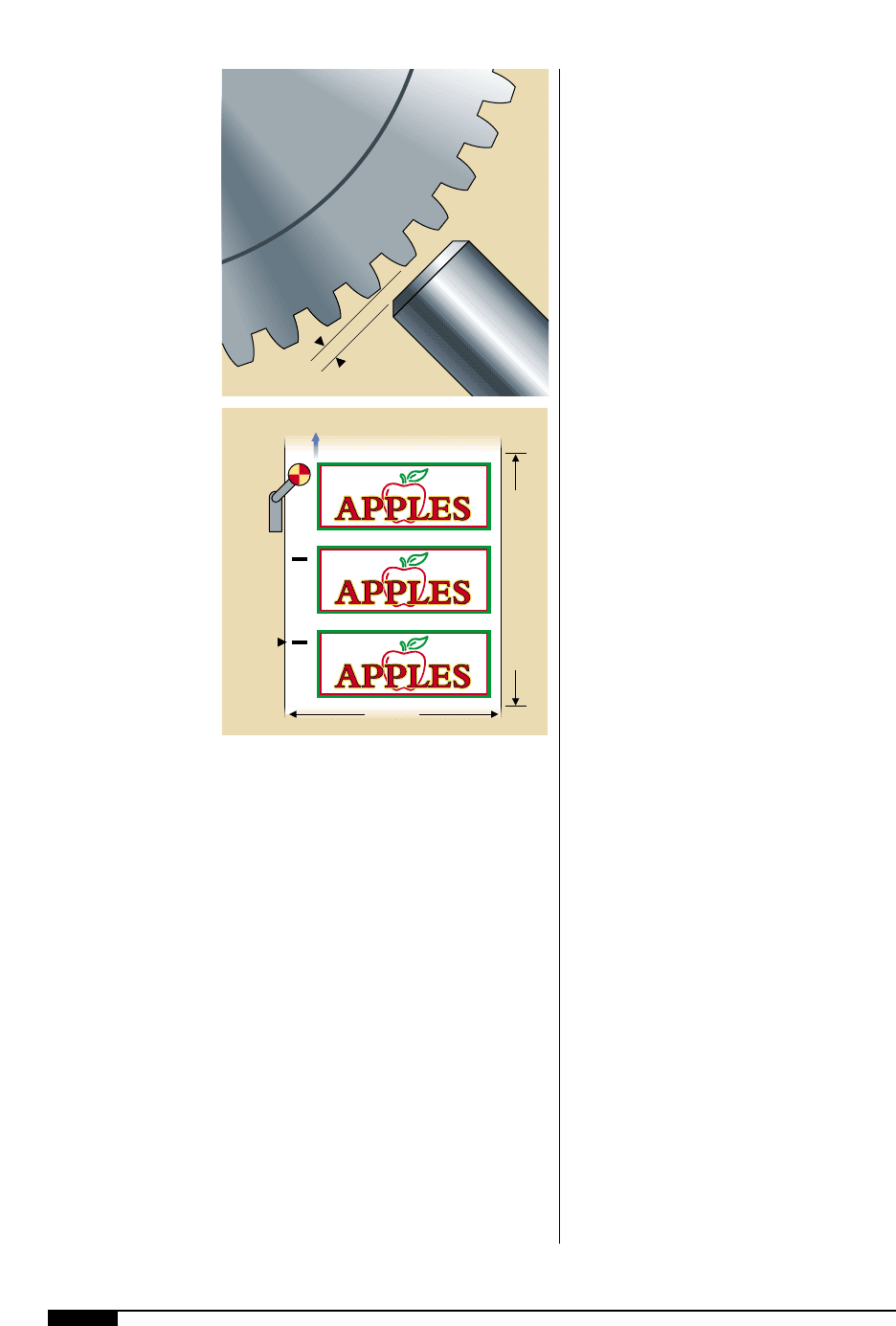
Proximity Sensor. The proximity sensor is an
inductive device that detects the presence or
absence of ferrous metal. It is most common-
ly used in video inspection systems to detect
and count the teeth on a gear that is relative
to the print cylinder. The proximity sensor
would be installed to sense the teeth of the
bull gear (Figure
4%
). It is critical for proper
operation of the video system that the dis-
4%
The proximity sensor
determines the number
of teeth on a bull gear,
and doing so, measures
the rate of web travel.
4^
A proximity sensor will
detect the beginning of
the repeat and then
develop strobe timing
pulses via software.
This type of sensor is
most commonly used in
non-printing applica-
tions such as inspection
rewinders.
78 FLEXOGRAPHY: PRINCIPLES & PRACTICES
tance between the proximity sensor and the
gear teeth being sensed (sensor gap) is adjust-
ed correctly. Incorrect setting will cause the
system to lose synchronization.
Since the pitch of the bull- and print-cylin-
der gears are known, this determines that
every four teeth detected by the proximity
sensor results in one inch of web travel. The
only setup information the video system
requires to synchronize properly is how many
teeth are on the print cylinder gear for the
current job. This value must be changed each
time a different size print cylinder is used.
Optical Encoder. An optical encoder utilizes
an internal transmitted-light sensor and a
transparent disk with non-transparent
marks equally spaced on the disk to gener-
ate a timing signal. This signal is directly
relative to the shaft of the encoder (i.e.,
each complete rotation of the encoder
shaft generates an exact number of timing
pulses).
This arrangement requires that the
encoder be geared to the press so that, for
each complete revolution of the encoder
shaft, the print cylinder also makes exact-
ly one revolution. Because of this exact 1:1
ratio requirement, the encoder has limited
applications. On a variable-repeat press, it
would require the operator to change the
encoder or gear ratio for every job change.
The optical encoder is most commonly
used on fixed repeat presses.
Print Mark Sensor. A print mark sensor can be
used to synchronize the video system by opti-
cally detecting a printed mark on the web sur-
face. The printed mark must be of significant-
ly opposing contrast to the background color.
The printed mark must only occur once per
printed pattern and no other printing can
occur between the marks (Figure
4^
). In this
mode the video system will detect the begin-
ning of the repeat and then develop strobe
timing pulses via software. This type of sen-
sor is most commonly used in non-printing
applications such as inspection rewinders.
One Print Cylinder Circumference
Crossweb
Machine Direction
Print
Mark
Sensor
Print
Marks
Proximity
Sensor
Sensor Gap
Bull
Gear
4%
4^

PRESSES AND PRESS EQUIPMENT 79
preset tolerances and warning the operator
when the press exceeds these tolerances, i.e.,
registration, color variance, repeat varia-
tions, etc. By changing illumination they also
have the capability of viewing clear varnish-
es and lacquers without using additives.
The biggest drawback to date has been the
cost of such units. They have obviously
appeared on the latest high-tech presses, but
it seems that it will be some time before they
are available as retrofits for older presses.
CONCLUSION
Video inspection systems are capable of
viewing high press speeds without jitter and
distortion. They are also capable of high
magnification and can detect printing
defects normally seen only with the aid of a
magnifying glass on a stationary web. They
are particularly helpful in detecting registra-
tion errors, doctor blade streaks, dot gain
and UPC code verification.
As these systems have evolved, they have
become capable of automatically monitoring
80 FLEXOGRAPHY: PRINCIPLES & PRACTICES
O
ne of the key functions of the
flexographic printing process
is the proper treatment and
handling of the substrate mate-
rial. One of the primary consid-
erations is, of course, the dry-
ing of the ink on the substrate after the print
stations. Further considerations include
additional treatment in order to receive the
ink, cleaning of the substrate and control of
static electricity carried by the substrate.
Finally, lamination and varnishing will be
briefly discussed.
DRYERS
Some flexographic presses have integrated
drying systems. A typical arrangement for a
central impression (CI) press is shown in
Figure
4&
. There are individual dryers after
each print station except the last one. These
dryers are known as either between-color or
interstation dryers. The dryer after the last
print station is called the main tunnel or over-
head dryer.
Interstation dryers remove a sufficient
amount of the volatile solvents from the ink so
that the next print station may apply another
color without altering the previous one. On a
four-color stack press there are typically three
interstation dryers. A color CI press usually
has five. On either a stack press or CI press,
there is one main tunnel dryer. The latter
removes the volatile solvents from the last
printing station and completes the heat setting
of all the inks applied. The main tunnel dryer
also removes the final traces of volatile sol-
vents from products where retained solvents
could present problems, such as blocking.
The interstation and main tunnel dryers
have various air flow schemes, depending on
the vintage of a press. For example, a press
Substrate Treatment
and Processing
4&
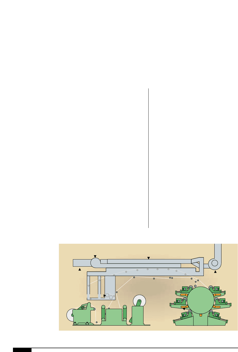
A typical dryer system
on a central impression
(CI) press. There are
individual dryers after
each print station except
the last one.
Dual
Burners
Interconnecting Ductwork
Drying Tunnel
Dual Exhaust
Blowers
Dual Supply
Blowers
Chill Rolls–PIV Controlled
Between Color Dryer
4&
PRESSES AND PRESS EQUIPMENT 81
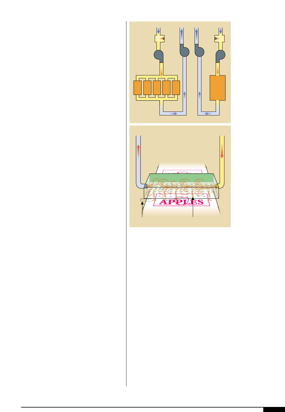
might have one supply fan, one burner and
one exhaust fan for the main tunnel dryer,
and a parallel system for the interstation dry-
ers, with each one sharing one supply fan and
one exhaust fan (Figure
4*
). This system
gives the press operator the ability to inde-
pendently control air temperatures in either
the interstation dryers or the main tunnel.
Other examples of airflow schemes are:
• one supply fan and one burner ducted
to both the interstation dryers and main
tunnel dryer, then exhausted through a
common exhaust fan;
• independent supply fans and burners,
but exhausted with a common exhaust
fan; and
• independent supply fans with one com-
mon burner with exhaust through an
independent or common exhaust fan.
As with any rule, there may be exceptions.
Some may exist where the interstation dryer
exhaust is also the main tunnel supply or vice
versa, as in a cascading airflow system.
Again, flexographic press dryers use hot
air to remove the volatile portion of the ink.
This air is ducted and directed to the sub-
strate where the substrate, ink solids and ink
solvents are raised to a temperature that
causes volatilization. The important consid-
erations for any dryer are:
Air Temperature. The higher the tempera-
ture, the quicker drying can occur, but
high temperatures can have drawbacks,
such as possible substrate damage. High
temperatures can also dry the top surface
of the ink, forming a crust that must be
broken to vaporize ink trapped under the
surface against the substrate. This defect
can show up as pock marks or “fisheyes.”
Air Velocity and Volume. The greater the
velocity and volume of heated air directed
to the substrate, the quicker the volatile
ink components can be vaporized. The ink
must reach the ink-vapor temperature for
volatilization to occur. The moving air
helps carry the volatile components away,
speeding additional evaporation. Velocity
and volume relate directly to fan horse-
power.
Time. Sufficient time with a proper combi-
nation of air velocity, air volume and air
temperature, allows the substrate and ink
to get hot enough to vaporize the volatile
component of the ink. The length of the air
dryer versus the linear speed of the sub-
strate determines the length of time.
How Dryers Work
Normally, the supply fan takes air, from
either the roof or inside the plant, past a gas-
fired burner and directs this air to the sub-
strate (Figure
4(
). The heated air is pushed
onto the substrate through a series of air
Heated
Air
Supply
Air
Exhaust
Boundary
Layer
Air
Nozzles
4(
Burner Burner
Between
Color
Dryers
Main
Tunnel
Dryers
4*
4*
A typical dryer air-flow
scheme.
4(
How a dryer works:
The heated air is pushed
onto the substrate
through a series of air
nozzles, narrow slots
running perpendicular
to the substrate travel,
across the width of the
substrate. After vaporiz-
ing the volatile compo-
nent of the ink, the air is
exhausted.
nozzles, narrow slots running perpendicular
to the substrate travel, across the width of
the substrate. After vaporizing the volatile
component of the ink, the exhaust fan pulls
the air from the dryer and sends it to either
the atmosphere or a pollution-control
device. When the air is exhausted, ambient
air is pulled into the dryer at the web
entrance and exit. In all cases, the exhaust
volume is greater than the supply volume.
Therefore, the dryer is kept under a slight
negative pressure, which prevents volatile
air from escaping into the plant.
NFPA Guidelines
The exhaust airflow volume from the
press dryer is designed according to
National Fire Prevention Association
(NFPA) guidelines which dictate that the
ventilation or exhaust rate must be
designed and maintained to prevent the
vapor concentration in the dryer from
exceeding 25% of the lower explosive
limit. The NFPA says that an estimated
rate of ventilation or exhaust cannot be
less than 10,000 cubic feet (measured at
70°F) per gallon of solvent evaporated in
the dryer. This rate makes for a 25% lower
explosive limit. This limit is based on
ink/solids/solvent concentrations, types of
solvents, press speed, substrate width and
the number of printing units. All these fac-
tors must be considered to determine the
maximum solvent conditions or the most
solvent the dryer will have to evaporate.
Now that pollution-control equipment is
mandatory, flexographic press dryer airflow
schemes have been revised to reduce the
volume of air processed by this equipment
and released to the environment. The EPA’s
capture requirements on total emissions
must be met, limiting the amount of air that
can be treated and exhausted.
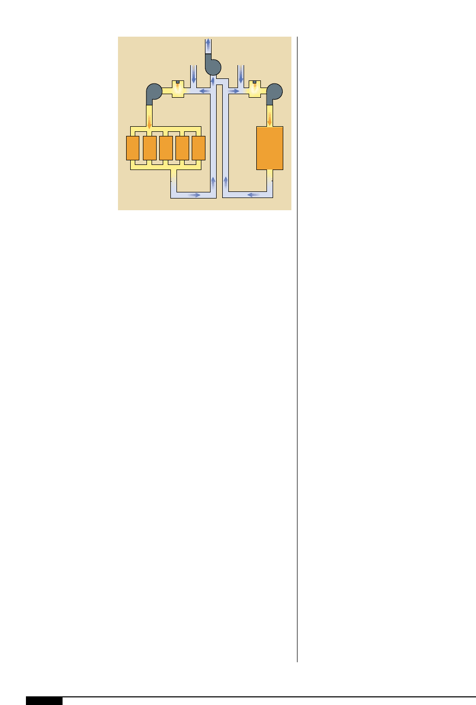
Most press manufacturers offer a recircu-
lation airflow scheme that recycles air con-
taining volatilized solvents (Figure
5)
). The
recirculation principle utilizes a supply fan
sized to provide the necessary volume and
pressure of hot air to the dryer and to
exhaust the majority of the air containing the
vaporized solvents. A smaller exhaust fan
removes the filtered air, products of combus-
tion and any leakage into the dryer. In all
cases, this exhaust must meet the guidelines
of NFPA for lower explosive limits. When
dealing with dryer exhaust rates, consult
your press or dryer manufacturer and the
proper authority in pollution control.
COOLING ROLLS
When subjected to heat, polymeric films can
soften, lose strength and stretch. Although
heat is required to complete some of the coat-
ing and printing operations, temperatures
must be carefully controlled, and this usually
necessitates the use of cooling rolls.
Cooling rolls can be devised by using other
rolls as substitutes, such as uncovered foun-
tain rolls, plate cylinders or impression
cylinders, in positions following the dryers,
between the last dryer and rewind, or where
a temperature reduction is necessary.
Heat Transfer
Regardless of the composition of the major-
ity of substrates, the heat transfer through
5)
A recirculation airflow
scheme that recycles air
containing volatilized
solvents.
82 FLEXOGRAPHY: PRINCIPLES & PRACTICES
Burner
Burner
Between
Color
Dryers
Main
Tunnel
Dryers
5)
