FTA (изд-во). Flexography: Principles And Practices. Vol.1-6
Подождите немного. Документ загружается.

PRESSES AND PRESS EQUIPMENT 103
6*
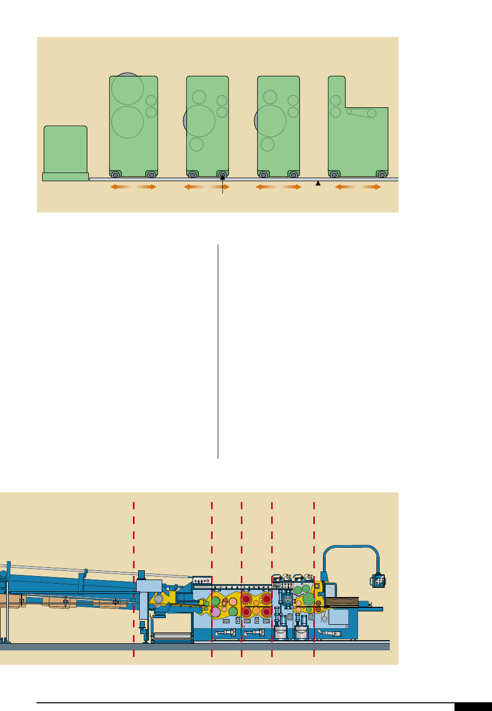
Close coupled
printing units of the
printer/rotary die-cutter
and flexo folder-gluer
machine have roll-away
press units, which allow
access to the various
printing elements for
setup and wash-up.
Adhesive Section
Die Cutter/
Creaser
Section
Creaser-
Slotter
Section
Printing Section
Feed Section
smearing or rubbing by folding or die-cutting
components. For example, a jam-up on a
rotary or platen die-cutting line with in-line
printing may cause production stops requir-
ing printing plate washing and causing sub-
sequent start-up waste.
SHEET FEEDERS
On corrugated sheet-fed presses, the first
element of importance is the feeding unit for
the sheets, which must ensure very good
register accuracy of each introduced sheet.
Registration tolerances have been in the
area of ±0.0625" for many years and have
steadily decreased for tighter tolerances.
Today, some manufacturers talk about toler-
ances of ±0.010", however, the reality is more
in the area of ±0.020" during production.
The following are short descriptions of dif-
ferent feeding principles, all of which can be
found on machines of different models.
Kicker Feeder
The kicker feeder is the oldest of all feeder
designs and works best with narrow sheets
in the throughput direction of a machine. It is
still found on so-called “mini-flexo” setups
because it is capable of introducing sheets at
speeds of 30,000 per hour. A stack of sheets
is placed on the vacuum bed and located
against a lead-edge stop plate (Figure
6(
).
Die-cut
Floor Track
RailMotorized
Casters
Fixed
Out Feed
Conveyor
Print #2 Print #1 Feed Section
6*
The vacuum draws the bottom sheet flat
against the feeder bed and the trail edge of
the sheet locates against the kicker fingers.
The kicker fingers, timed to the press rota-
tion, then push the bottom sheet into the feed
roll nip. Feeding accuracy depends on manu-
al adjustments, board warp, consistency of
the pre-trimmed sheets and whether or not
the feeder is equipped with a suction-assist.
Kicker feeders can only feed sheets with
their corrugation oriented in the machine
direction. If the direction of the corrugations
is across the machine, feeding against the
soft edge may result in very inaccurate regis-
ter or frequent jamming. E-flute is generally
the lowest flute profile that can be fed with
such feeders. F- and N-flute are too fine for
this type of feeder. It is safe to say that kick-
er feeders are not found on high graphics
machines.
Lead-edge Feeders
The most significant advantage of suction-
plate feeders is that the corrugated sheets
are accurately registered against their lead-
edge. Therefore, trimming variations from
the corrugator have less influence on feeding
accuracy. Vacuum distribution may be
achieved through rotary or piston-type
valves. On suction plate feeders (Figure
7)
),
powerful vacuum pumps – which can main-
tain a vacuum of 18" to 22" Hg under produc-
tion conditions – are needed, otherwise, slip-
page between the suction plate and the sheet
will occur.
Vacuum timing at start and release is im-
portant. Most suction plate lead-edge feed-
ers are timed as follows:
• The stroke of the plate must correspond
to the distance from the in-feed gate to
the center of the feed rolls, at a minimum.
• Suction must begin during a standstill
cycle (hopefully prolonged), when the
plate is in its most backward position.
• The suction plate must release the sheet
when the sheet has arrived at the center
of the in-feed roll nip.
• The speed of the suction plate and the
surface speed of the in-feed rolls must
be 1:1 to eliminate the vacuum at the
time when the sheet has to be released.
Venting to the atmosphere or injection
of compressed air are two methods
commonly utilized.
Belt Type. Belt type lead-edge feeding by fric-
tion goes back several decades and is found
on folder-gluer machines, both in the folding
carton and the corrugated industries (Figure
7!
). Continuously running belts pull one
blank after another, from underneath a stack
of blanks or sheets, in an “untimed” manner.
Obviously, to apply a similar technique on
a printing machine, the process needs to be
104 FLEXOGRAPHY: PRINCIPLES & PRACTICES
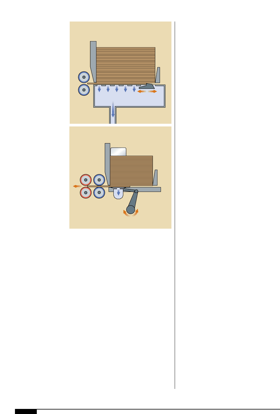
6(
Trail-edge kicker units
are still found on so-
called “mini-flexo”
setups because they are
capable of introducing
sheets at speeds of
30,000 per hour and
work best with narrow
sheets in the throughput
direction of the machine.
7)
During production,the
suction-plate feeder
allows corrugated
sheets to be accurately
registered against their
lead-edge by using
powerful vacuums to
help prevent slippage
between the suction
plate and sheet.
Feed
Rolls
Board
Stack
Vacuum Chamber
Kicker
Feeder
Back
Plate
Lead
Edge
Plate
Feed
Rolls
Pull
Rolls
Board
Stack
Side
Plate
Vacuum
Chamber
Actuator Arm
Back
Plate
Lead
Edge
Plate
6(
7)
timed. A vacuum fan is utilized to ensure a
slippage-free transport of each sheet. In its
simplest form, such a feeder has continuous-
ly running belts over a suction box or cham-
ber which has lifters that, in a timed fashion,
lower the stack of sheets onto the belts,
allowing the lowermost blank to be intro-
duced into the feed roller nip. The vacuum is
continuous and needs only to be interrupted
when feeding needs to be stopped.
Reciprocating Belt Feeder. Another type of
lead-edge belt feeder has reciprocating belts
with forward and backward motion. With this
design, the belts are lifted through cam rollers
to meet the lowermost sheet of a stack lying
on top of stationary slats. The feeding cycle
consists of four steps:
• The stationary belts are lifted above the
slats.
• The belts move forward in lifted posi-
tion to introduce the sheet into the feed
rollers.
• The belts are lowered away from the
sheet at the end of the forward stroke.
• Backward movement of the belts in
lowered (non-contact) position below
the slats completes the cycle.
Roller-type Feed Wheels. This category of
lead-edge feeder is also based on a high vol-
ume vacuum, which transports the sheet on
continuously rotating feed wheels that are
covered with a high friction material. Timing
is controlled through a vertically-arranged
lifting grid (slats) that has a low friction sur-
face. The up-and-down cycling, generally
done through a cam arrangement, deter-
mines when a sheet starts its travel forward
and when it is to be taken over by the feed
rolls in pace with the machine.
With feed-wheel or feed roller-type lead-
edge feeders, many variables in design exist.
Generally speaking, such feeders are very
reliable and good feed accuracy is obtained.
Such feeders can feed stock with excessive
warp to the point that a jam-up somewhere in
the printing units may occur, which is poten-
tially a bigger evil compared to a jam-up in
the feeder. Flat sheets are, on all types of
feeders, the best insurance for trouble-free
operation of a machine.
Cam Roller Feeder. With this type of feeder,
small quantities of blanks are placed in the
feed table hopper by the operator or an auto-
matic pre-feeding device. The leading edge of
the sheet locates against vertical fingers that
are set above the feed table to allow only one
sheet to pass at a time (Figure
7@
). A set of
cam-shaped feed wheels contacts the bottom
blank in the pile and pulls it into the nip of
the feed rolls. The feed rolls grip the blank
and delivers it to the printing section.
PRINT STATION
Having examined the different substrate-
feeding methods, it is now time to look at the
next step in the process: the print station.
There is more to printing than simply apply-
ing ink. Proper mounting, gear and roll posi-
tion and technique are all important factors.
Top Printing vs. Bottom Printing
Flexo printing on corrugated evolved in a
round-about fashion. It was developed or
integrated into various existing manufactur-
ing processes and has only existed as a self-
PRESSES AND PRESS EQUIPMENT 105
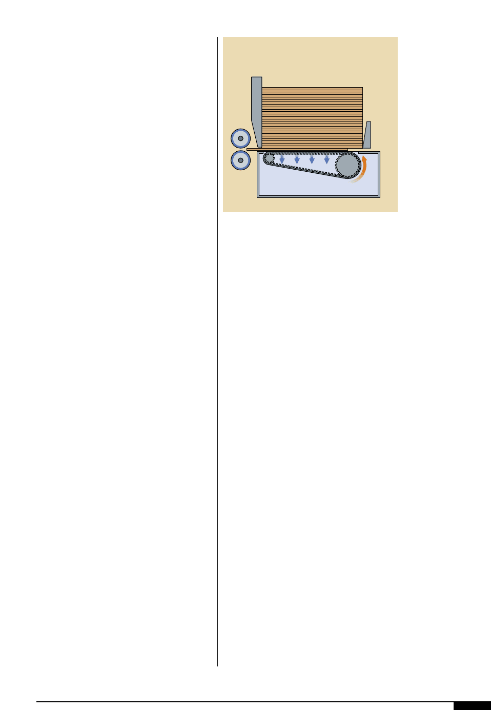
7!
In a belt-type feeder, the
lowermost blank is
pulled from a stack of
blanks or sheets, and
pushed through the feed
rolls to the folder-gluer.
Feed
Rolls
Board
Stack
Vacuum Chamber
Back
Plate
Lead
Edge
Plate
7!
106 FLEXOGRAPHY: PRINCIPLES & PRACTICES
contained off-line process since the late ’70s.
For this reason, top-and-bottom printing units
were developed to adapt the printing units to
whatever converting operation already exist-
ed. Top and bottom printing are each applica-
ble in different circumstances. For example:
• On a folder-gluer with an “up-folding”
principle, the printing needs to be on the
bottom of the sheet.
• On a so-called “down-folder”, the print-
ing is performed on the top of the sheet.
• On a rotary die cutter with the rotary cut-
ting die on the top shaft, printing needs
to be on the bottom because the creasing
lines to form a box or container must be
on the inside of the box.
• Conversely, if the cutting die is on the
bottom shaft, the printing must be on
top. The same principles apply for plat-
en-type die cutters.
The quality of flexo printing on corrugated
sheets, whether performed from the top or
from the bottom, is not truly an issue. Rather,
the key question is: Which approach is better
aligned with the overall scope of the total
corrugated manufacturing and converting
process? One way to address this question is
to begin with the corrugator. Consider the
following:
• The corrugator, without exception, deliv-
ers the combined sheet with the print
liner on the bottom.
• The majority of corrugators have auto-
matic down-stackers or up-stackers that
deliver piles of combined sheets with the
print liner on the bottom.
• The majority of pre-loaders deliver the
sheets into the feeders of converting and
printing machines from the top of piles in
batch form or in a shingle stream. Others
deliver sheets from the bottom in a shin-
gle stream, without turning them over.
• Most rotary or platen die cutters cut from
the top and therefore need the printing
on the bottom.
• Stitching machines and tape applicators
insert staples or apply box-joining tape
from the top.
In all of the above cases, printing must take
place on the bottom of the sheet. While all
the above scenarios can be overcome, it
would certainly be at the cost of additional
equipment, such as pile turning devices.
On a top printer, the printing is done above
the board line (where board dust and debris
cannot fall onto the printing plates) and away
from floor-level dirt (Figure
7#
) One major
advantage of top printing is that the printed
image can readily be seen without removing
a sheet from the in-line process.
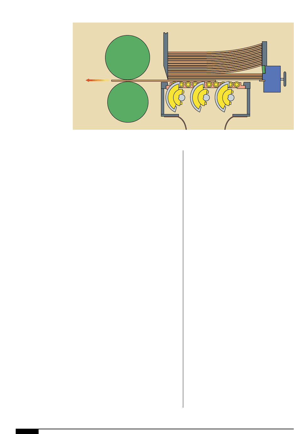
7@
With a cam roller feeder,
a set of cam-shaped
feed wheels contacts the
bottom blank in the pile
and pulls it into the nip
of the feed rolls.
To Printing
Section
Feed Rolls
Cam Roller
Feed Wheels
Vacuum
Chamber
7@
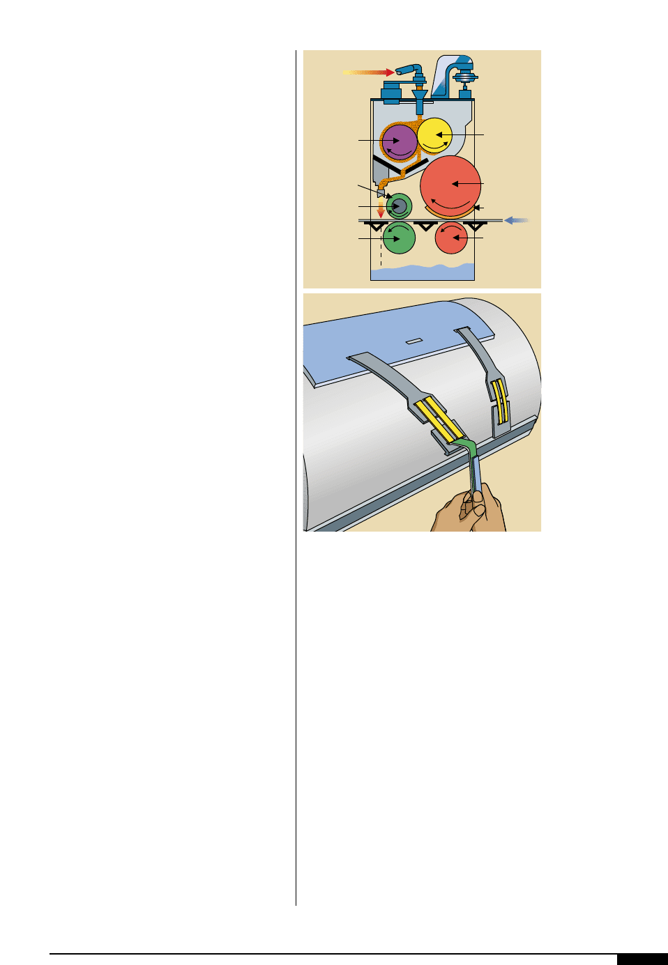
Plate Mounting
Generally speaking, photopolymer plates
have made tremendous progress in corru-
gated printing and are used almost exclu-
sively today, especially in the value-added
graphic arts field.
On sheet-fed corrugated flexo presses,
plates are very seldom glued directly onto
the print cylinder. However, this practice
does still exist for mounting so-called “slugs,”
i.e., when only a box certificate or a bar code
is needed. For such applications magnetic
cylinders are generally preferred, where the
printing plates are pre-mounted on 0.010"
sheet steel.
Plate mounting methods in corrugated
vary. However, the most widely used method
uses polyester, vinyl or other plastic materi-
al, 0.030" thick, onto which the plates are
glued. This plastic mounting or carrier sheet
is provided with a lead-edge hook, which
locates into a slot on the press cylinder
(Figure
7$
). Slots are provided in the tail
end of the mounting carrier sheet, where
elastic straps are used to tighten it around
the printing cylinder.
Several other mounting methods exist,
such as full wrap-around systems with a
take-up device, as well as steel-backed plates
for mounting onto magnetic cylinders.
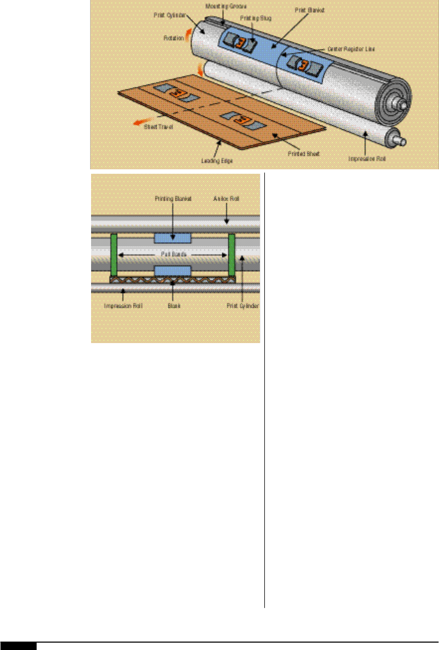
In a typical high-production box plant, plate
slugs are mounted on print carrier sheets. The
slugs are designed according to customer
specifications and ordered from an outside
supplier. The designs are often simply com-
pany logos, but can be made for almost any
graphic design, including halftone screens.
Text can also be engraved on the slugs.
The slugs are made of photopolymer or
rubber compounds that easily conform to the
round shape of the print cylinder. When the
slugs have been manufactured and delivered,
they are mounted onto a carrier sheet. A
number of different slugs can be attached to
a single carrier sheet. All slugs required for
printing a single color are mounted on one
carrier sheet and arranged to register with the
panels of the final printed boxes (Figure
7%
).
A centerline mark is placed on the print car-
rier sheets and on the print cylinder.
Centerline marks are used as a tool for
mounting the print carrier sheets in the cor-
rect location on the print cylinder. When the
machine is running, the centerline of the
sheet should be aligned with the centerline of
the print cylinder. Pin registering systems
may also be installed on the press and the car-
rier sheet to facilitate correct plate-mounting
and registration on a press.
Pull Bands
In addition to the print carrier sheets, pull
bands are also placed around the print cylin-
PRESSES AND PRESS EQUIPMENT 107
7#
With its print
components positioned
above the board line,
a top printer allows
visual inspection of a
job without having to
remove a sheet from the
line.
7$
A popular method of
platemounting for
corrugated involves use
of a plastic mounting or
carrier sheet with a
lead-edge hook that
locates into a slot on
the press cylinder,
corresponding with the
slots on the tail end of
the mounting sheet.
The elastic straps are
then tightened around
the printing cylinder.
Anilox Roll
Print Cylinder
Printing Plate
Impression
Roll
Wiper Roll
Pull Roll
Collar
Pull Roll
Shaft
Pull Roll
Ink
7#
7$
108 FLEXOGRAPHY: PRINCIPLES & PRACTICES
7%
In this mounting
scheme, plate slugs
have been mounted
about a center register
line, which is used to
aid in locating the
corner sheet on the print
cylinder.
7^
Pull bands, placed
outside the width of
the print blanket, will
grip the outside edges
of the sheets as they
pass through the print
station, holding the
sheets in position
during the printing
process and advancing
them to the next station.
der (Figure
7 ^
). The pull bands are placed
outside the width of the print blanket, where
they will grip the outside edges of the sheets
as they pass through the print station. On
large, full-cover images, the pull bands may
be incorporated with the printing plates on
the same carrier sheet. Using pull bands will:
• eliminate skewing for square boxes;
• eliminate shallow slots for better-
closing boxes; and
• eliminate floating in the print station
for better print register.
Pull bands are used when small sheets
(less than 22") are run through the machine.
The pull bands help to hold the small sheets
in position during the printing process and
advance them to the next station. They are
also used when there is not enough printing
plate in contact with the sheet to hold the
sheet square as it moves into the next nip
point. Pull bands are necessary when only
one end of the sheet is being printed.
Any time that a print cylinder does not
have a print blanket mounted on it, pull
bands that wrap all the way around the cylin-
der should be used. Use of wrap-around
bands eliminates the setup time of trying to
register small bands to a small box.
Counter-impression Roll
The counter-impression roll is a smooth
steel cylinder located directly opposite the
print cylinder, forming the impression nip.
The impression roll imparts a light pressure
on the back face of the blank as it passes over
the printing plate. The light pressure exerted
ensures a positive contact of the liner with the
printing plate, necessary for transfer of ink.
The nip with the printing plate also assists in
pulling the blank through the press.
Permanent-mesh Coupling
The position of the impression roll with
respect to the print cylinder is important to
the efficient operation of the machine and
the print quality on the blank. The gap
between the print cylinder and the impres-
sion roll should allow contact between the
blank and the printing plate without crush-
7 %
7 ^
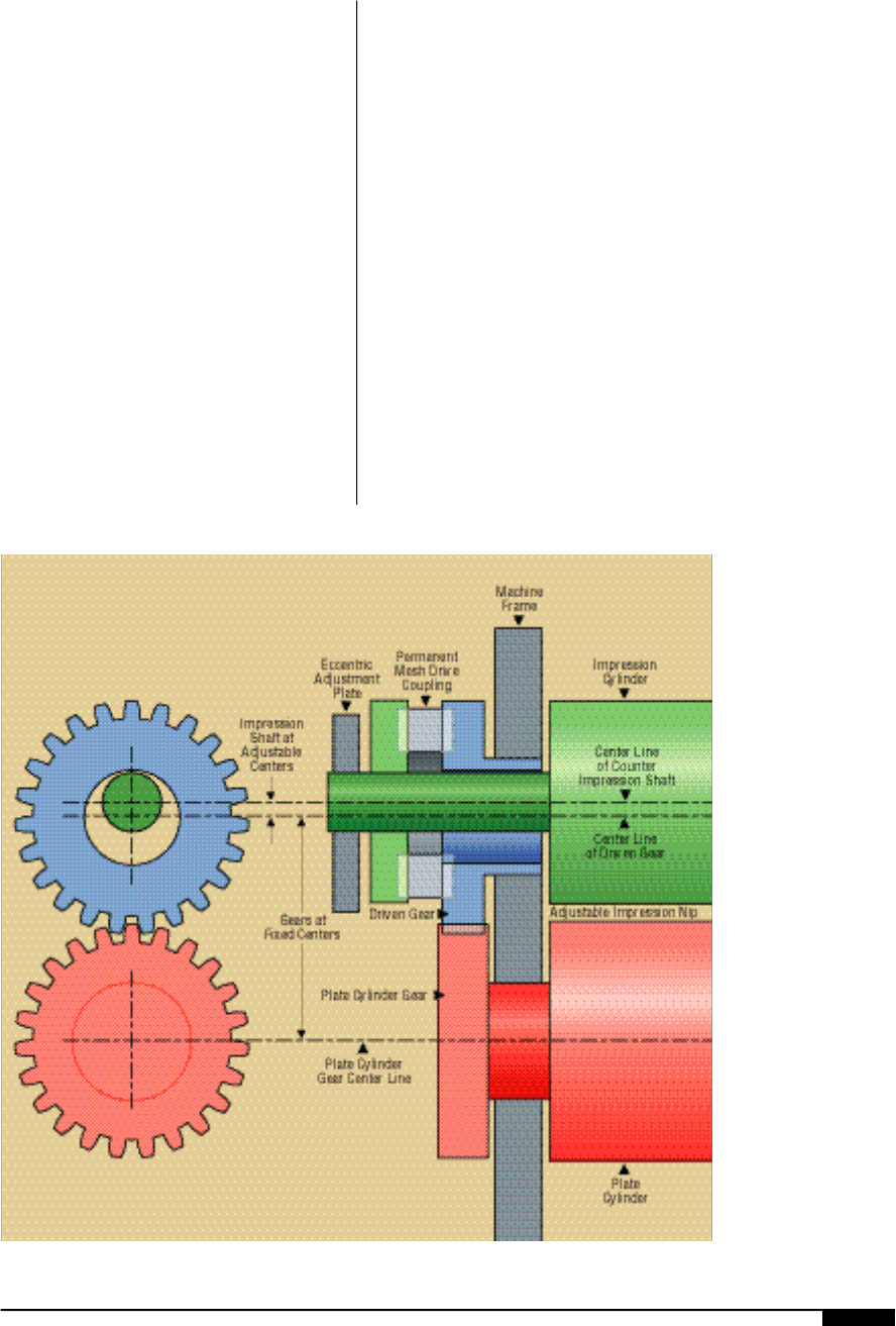
ing the blank. The range of nip adjustment
necessary to accommodate various calipers
of combined board, i.e., 0.040" to 0.300" (1
mm to 7.6 mm), is achieved by the use of a
permanent-mesh drive coupling mounted
between the driven gear and the counter
impression roll drive (Figure
7 &
). This cou-
pling allows the gears in the drive system to
remain in a constant mesh position while
allowing the impression roll to be moved.
These permanent-mesh couplings are also
used on other shafts such as the anilox roll,
pull rolls and slotter shafts, where a large
range of nip adjustment is required.
Inks
In flexographic postprinting, water- r e -
ducible inks are used almost exclusively.
The biggest challenge in corrugated post-
print for ink suppliers is to overcome the
wide range of substrate variables. There-
fore, wide volumetric differences of anilox
rolls are used to try to conform the box or
display to consumer specifications. In corru-
gated postprinting, ink consumption may
vary from run to run: from as little as 2.5
B C M / i n
2
(billion cubic microns per square
inch) on a high-holdout liner to 10 BCM/in
2
on a high-recycle content kraft linerboard.
It is still a trend today to supply the corru-
gated industry with fast-drying inks (one of
the attributes of flexo inks) even though dry-
ers are installed on many presses.
Anilox Rolls
There are no limitations as to what type of
anilox roll may be used for corrugated print-
ing. Because of economics, mechanically
PRESSES AND PRESS EQUIPMENT 109
7&
Permanent mesh-drive
coupling between the
driven gear and the
counter impression roll
drive allows the gears in
the drive system to
remain in a constant
mesh position, ensuring
proper contact between
the printing plate and
blank.
7 &
110 FLEXOGRAPHY: PRINCIPLES & PRACTICES
engraved rolls are the most commonly used;
h o w e v e r, use of laser-engraved ceramic rolls
is increasing.
Since process printing on corrugated is
finding more and more applications (even on
old machines), improvements in print quality
are needed. The first improvement necessary
is to obtain better ink metering through the
use of finer (laser-engraved) anilox rolls. In
many cases, retrofits of reverse-angle doctor
blades or even chambered doctor-blade sys-
tems can improve print quality. The long life
span of laser-engraved ceramic-coated rolls
with blade-doctoring systems seems to offset
the additional purchase cost for laser-
engraved versus mechanically engraved rolls.
Because of the very wide spectrum of
graphics printed onto even more variable
substrates, almost any shape of anilox cell,
widely varied volumetric capacities and
probably any available screen-angle (en-
graving angle) can be found on different cor-
rugated flexo presses.
SHEET TRANSPORT SYSTEMS
In order to print correctly, each sheet
transported through a flexo press must trav-
el at the exact same speed as the circumfer-
ential speed of the print cylinder. Since the
inception of flexo printing, sheet con-
veyance has been assured through pull
rollers, also called pull collars, from the
feeder through the printing units and other
converting elements.
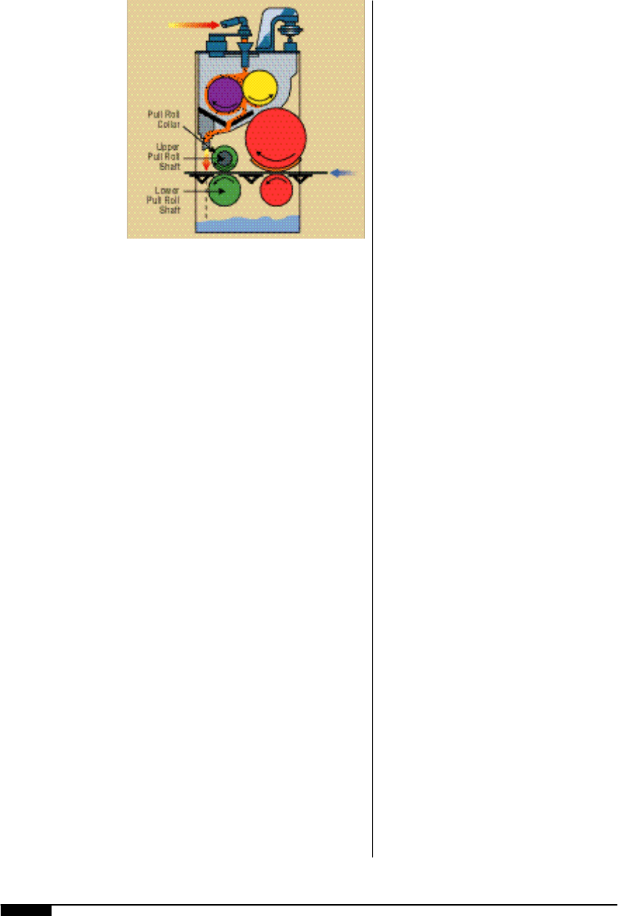
Pull-roller
On a flexo folder- g l u e r, two steel pull-roll
shafts are located in each printing station
(Figure
7 *
). The purpose of the pull rolls is
to control the blanks and, on the last print
station, to crush the fluted edges where the
two ends of the box are glued together.
Thus, when the blank is folded into a box,
the overlapping parts will not be thicker
than the walls. This procedure allows the
boxes to stack flatter when folded. If the
fluted edges are not crushed properly, the
finished boxes will bow in the middle and
will not stack evenly.
The upper roll has two laterally adjustable
collars on the shaft, one for each end of the
blank. The pull collars on the printing station
are serrated, whereas the collars on the last
station are designed to crush the flutes on
the edge of the board so that the board edge
will not spring back into shape.
The nip formed by the collar and lower pull
roll is used to grip and pull the blanks
through the printing station. The nip, or gap,
between the pull collar and the bottom pull
roll is adjustable. The gap must be set
according to the caliper of the blanks being
used. If the gap is too wide, the blanks will
not be held securely during the printing
process and registration will not be held. If
the gap is too narrow, the blanks will be
crushed, resulting in reduced box strength.
The distance between pull roller nips dic-
tates what minimum size sheet can be
processed in the throughput direction of the
machine. On a machine with pull roller nips
18" apart, the minimum sheet throughput
dimension needs to be 18.375", so that it
remains in control between nips at all times.
Any time a print cylinder does not have a
print blanket mounted on it, pull bands that
7*
Pull rolls control the
blanks and, on the last
print station, crush the
fluted edges where the
two ends of the box are
glued together.
7 *
wrap all the way around the cylinder should
be used (See Figure
7 ^
). Wrap-around pull
bands eliminate the setup time of trying to
register small bands to a small box. When
positioning pull bands on the print cylinder,
they should be set on the edges of the sheet to
provide an equal pull across the sheet.
Pull-roller pressure must be adjusted to
hold each sheet firmly in order to avoid slip-
page or skewing. Diameters of pull collars
must be extremely accurate and should be
checked frequently for wear or ink and fiber
buildup. Even with all parameters in good
working shape, pull roller machines gener-
ally yield register tolerances of ±0.0312"
between two printing units.
Since most pull-roller machines are gener-
ally linked from gear to gear, cumulative
register variations over several printing
units may be severe. However, several thou-
sands of this type of machine are success-
fully used throughout the world to satisfy
printing criteria in the corrugated field.
Vacuum and Belts
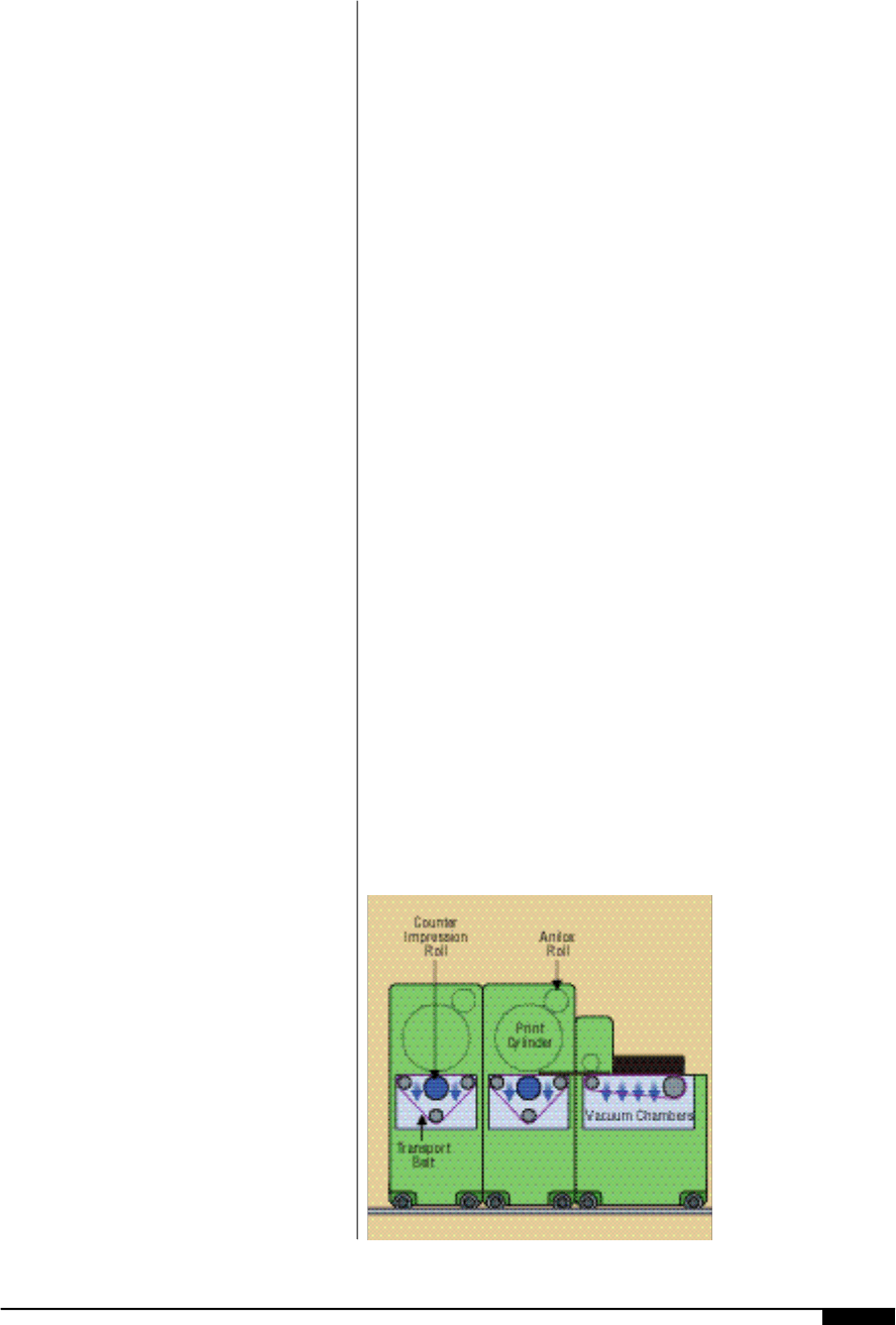
Several pull-vacuum belt transport systems
for sheet transport through flexo units (and
other elements) can be found today on cor-
rugated sheet-fed printing presses. One such
system, used on a top printer, has a long, end-
less timed belt with vacuum holes. The belt
reaches from the feeder, starting after the in-
feed pull rolls, through two, or up to four,
printing units (Figure
7 (
). This sheet trans-
port belt actually travels over the counter-
impression roll, holding the sheets while they
are being printed. The belt is of uniform
thickness to assure even ink transfer onto
the board it transports. The belt is kept in
correct timing and at the correct speed by
timing belts vulcanized to its underside.
This system assures improved register
compared to a pull roller machine. How-
e v e r, the belt is prone to becoming dirty and
clogged if ink spills into the inking units. Ink
spillage is one of the disadvantages of top
printing, since the sheets and transport sys-
tem are below the inking units.
Another vacuum-belt transport design
incorporates vacuum belt sections between
printing units, with several belts side by side
reaching from the exit of a printing nip to the
entrance of the following one. In certain
cases, such belts are movable across the
width of a machine, according to sheet size.
The more common design has multiple per-
manently positioned belts spaced across the
machine width, with a vacuum strong
enough to hold any size sheet.
One design incorporates speed adjust-
ments, by servo drives, of any transport belt
section between printing units to correct for
possible register inaccuracies. Vacuum belt
transports are a significant improvement
over pull roller sheet transports.
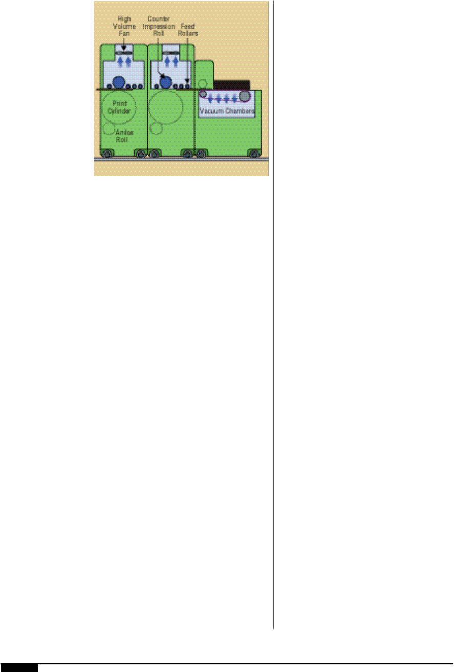
Rollers and Vacuum
The latest design for sheet conveyance
through a printing press incorporates close-
ly spaced precision rollers (Figure
8 )
) .
Large vacuum fans pull the sheets against
these rollers with a force equal to about 2" of
water column. The transport rollers have a
circumferential speed corresponding to the
print cylinder’s surface speed. Such an
arrangement assures an extremely high-pre-
cision sheet transport without skipping or
PRESSES AND PRESS EQUIPMENT 111
7(
A vacuum-belt
transport system
assures improved
register compared to
a pull roller machine.
The timed belt reaches
from the feeder through
the printing units.
This sheet transport belt
actually travels over the
counter-impression roll,
holding the sheets while
they are being printed.
7 (
112 FLEXOGRAPHY: PRINCIPLES & PRACTICES
skewing. On some of the latest presses a vac-
uum is even created around the counter
impression cylinder, assuring that the sheets
are pulled perfectly flat. This method
assures so-called “kiss” contact between the
printing plates and the corrugated sheets.
This type of vacuum transfer is generally dri-
ven by a line shaft through as many printing
units as are necessary.
The many advantages of such a sheet trans-
port system are: register accuracy of ±0.008"
through six-color stations can be achieved
reliably; full-coverage printing, side to side
and front to back, without any trim, is easily
achieved; no setup time is needed; and no
contact on or near any printing is ever made,
in contrast to pull-roller machines.
PRINTER-SLOTTER
The printer-slotter was probably the first
machine to be equipped with in-line flexo
units, replacing the letterpress printing units
from which flexo-printing units have evolved.
The printer- s l o t t e r, as a self-contained enti-
t y, still exists today. However, it is mostly
used to produce very large boxes in small
quantities. Most of these machines are fed
manually and have either a kicker bar or
chain feeder. Almost without exception, a
very simplel a y - b o ybelt stacker is used to col-
lect the finished printed-and-slotted blanks.
In a few cases the printer-slotter is equipped
with more automation and may fall into the
category of “jumbo” flexo-folder- g l u e r . Such
machines can handle blank sizes up to 104" x
210" for the production of furniture boxes and
other bulk boxes or containers. In most
cases, one or two flexo units, in their simplest
form, with roll-to-roll metering, are in-line
with such machines. While the printing may
not be very sophisticated, the need for graph-
ics with text or symbols can be achieved as an
in-line operation.
PRINTER DIE CUTTERS
There are two categories of printer die cut-
ters: the printer with rotary die cutting, and
the printer with platen-type die cutting. In
North America, the printer/rotary die cutters
outnumber printer/platen die cutters by a
ratio of about 10 to 1. In Europe, this trend is
exactly the opposite. Rotary die cutters,
known for their simplicity and high speed, are
today available in various degrees of sophisti-
cation with up to six flexo printing units in-
line. Any ink metering system, from roll-to-
roll to combination systems of roll-to-roll plus
chambered or reverse-angle doctor blades,
are offered by a growing number of manufac-
turers. Print register accuracy of ±0.020"
through all colors and process printing up to
85 and 100 dpi are achievable. In its more con-
ventional form, the printer/rotary die cutter
(soft anvil die cutting) is considered a “work-
horse” in brown box plants, where 15% to 18%
of production consists of die-cut blanks.
FLEXO FOLDER-GLUER
An entire book on the flexo folder-gluer has
been written by Joel J. Shulman and was first
published in 1986. It took Shulman six years
to gather technical input on flexo folder- g l u e r
operations alone, without getting into in-
depth printing techniques on corrugated
8)
Closely spaced
precision rollers with
circumferernetial speeds
corresponding to the
print cylinder’s surface
speed assure extremely
high-precision sheet
transport without
skipping or skewing.
8 )
