FTA (изд-во). Flexography: Principles And Practices. Vol.1-6
Подождите немного. Документ загружается.

PRESSES AND PRESS EQUIPMENT 63
It is important to note that the feedback to
the sensor is through the web. Thus, the
behavior of the web, in conjunction with the
other components in the loop, is most impor-
tant to the proper functioning of the control
system. Not only are the characteristics of
these individual components important, but
the relationship of their characteristics must
be carefully established to ensure proper sys-
tem results. The accuracy of this feedback is
particularly true where high press speeds
require fast guiding system response and sta-
bility to achieve highly accurate web position
control and registration.
Various auxiliary control systems are
available for use with the automatic guiding
systems. With intermediate guides, the most
common auxiliary control system is a fea-
ture that allows the operator to disable the
automatic guiding system and to center the
intermediate guiding device in its travel. This
feature is generally most useful in situations
where the press must be re-threaded. With
unwind and rewind guides, the most com-
mon auxiliary control system is a feature
that enables the operator to manually con-
trol the system, as well as to operate in the
automatic guiding mode. With this system,
the operator can manually position the
unwind or rewind stand during press setup
and then switch the system into the normal
automatic mode of operation when printing.
There are three locations on flexographic
presses where guiding is normally applied at
the unwind, prior to printing and at the
rewind. Guiding at the in-feed section with
Plate Thickness
1.00
.250
.187
.125
.100
.067
.155
.045
.030
0.95
0.90
0.85
0.80
0.75
0.70
51015202530354045505560
3#
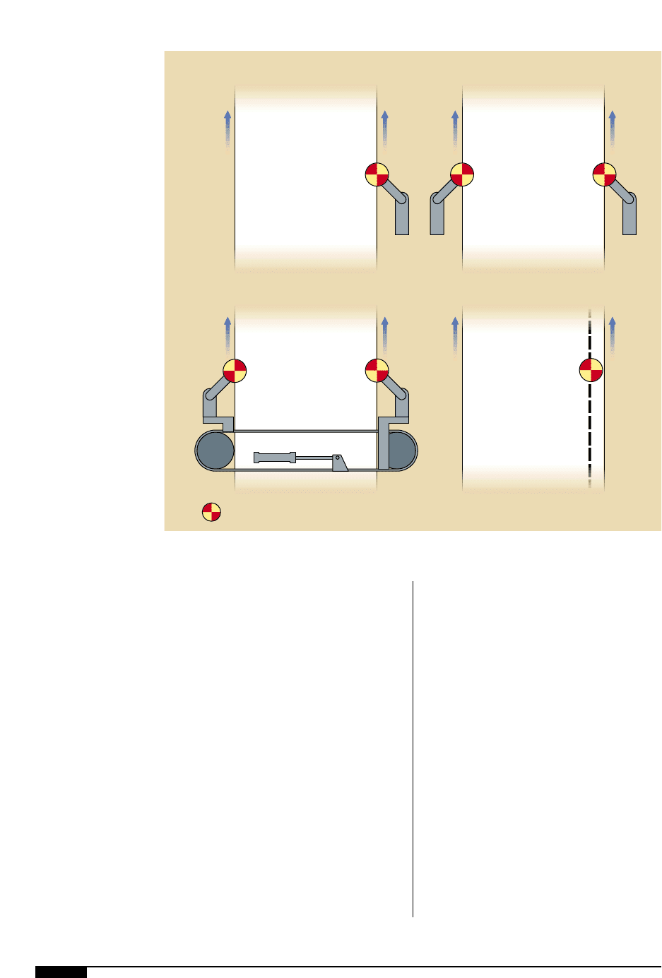
The four types of
automatic guiding
systems. All of these
systems rely on a
sensor to monitor
web position and
transmit any shifts to
a servo valve (hydraulic
systems) or a DC drive
motor (mechanical
systems).
3#
either unwind guiding or intermediate guid-
ing corrects for misalignment of mill roll
position and such things as telescoped and
poorly wound rolls.
Automatic Web Guiding Systems
There are four basic types of automatic
control systems (Figure
3#
):
• pneumohydraulic;
• electrohydraulic;
• pneumomechanical; and
• electromechanical.
All of these systems are closed-loop, type 1,
proportional control systems; this description
means the correction output adjustment is
opposite and in proportion to the error
detected.
Hydraulic types. The two hydraulic types of
automatic control systems function in a sim-
ilar manner. A sensor monitors the lateral
position of the web. The sensor signal is
transmitted either directly to the power unit
servo valve (pneumohydraulic systems) or to
a signal processor, which then sends a signal
to the power unit servo valve (electrohy-
draulic systems). Hydraulic output from the
power unit through the servo valve, propor-
tional to the lateral error of the web, posi-
tions the guide structure, which moves the
web to the correct lateral position in the sen-
sor. These systems are attractive for
extremely heavy loads and harsh environ-
ments.
Mechanical types. The two mechanical types
of control systems also function in a similar
3$
The four types of
web-position control
systems. Note the
varying positions of
the sensors.
64 FLEXOGRAPHY: PRINCIPLES & PRACTICES
Web
Edge Guiding
Web
Fixed Sensor Center Guiding
Web
Moving Sensor Center Guiding
Web
Line or Pattern Guiding
= Sensor
3$
PRESSES AND PRESS EQUIPMENT 65
manner. A sensor, either electronic for
electromechanical systems or pneumatic for
pneumomechanical systems, monitors the
lateral position of the web. The sensor signal
is either transmitted directly to the signal
processor (electromechanical system) or is
first converted from an air pressure signal to
an electrical signal with a transducer (pneu-
momechanical system). The processor then
sends a signal, proportional to the amount of
error detected by the sensor, to the DC drive
motor on the electromechanical actuator.
The actuator positions the guide structure,
which moves the web to the correct lateral
position in the sensor.
These systems are especially attractive for
applications demanding a high frequency re-
sponse and where hydraulics are not
desired.
Web Position Control
There are four types of web-position con-
trol systems (Figure
3$
):
Edge Guiding. The sensor detects the web
edge and the guide system maintains this
edge at the desired lateral position.
Fixed Sensor Center Guiding. Two sensors are
held in a fixed position; they detect both
edges of the web. The guide system main-
tains the centerline in an exact position and
accommodates small web width variations.
Moving-Sensor Center Guiding. In applications
where there are large web width variations
during a production run, the sensors contin-
uously reposition themselves automatically
to detect both web edges and to maintain the
centerline of the web in an exact position.
Line or Pattern Guiding. The sensor detects a
printed line, pattern or some distinguishable
feature on the web. The system then main-
tains the printed line, pattern or feature in an
exact lateral position, regardless of the web
edge position.
Sensor Installation
The sensor should be located in the exit
span as close as possible to the exit guide
roller and no farther downstream than one-
half the exit span length. A dead-bar or idle
roller can be used to stabilize the web and
prevent the web from contacting the sensor.
The dead-bar or idle roller should be posi-
tioned immediately downstream of the sen-
sor and have a web wrap no greater than 10°.
Sensor selection is based on material and
system requirements.
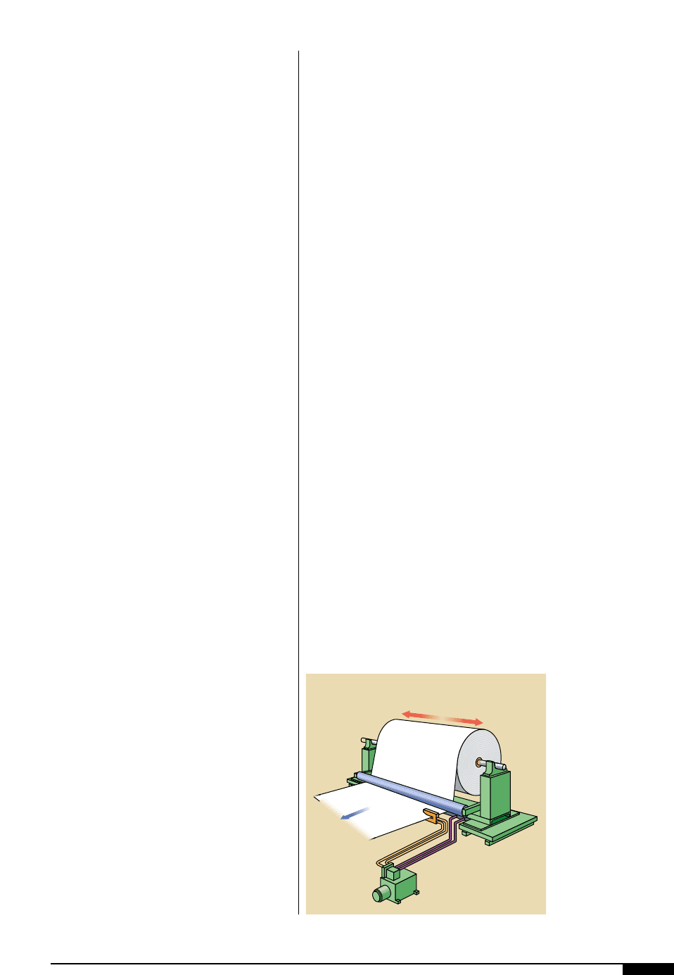
UNWIND GUIDING
A typical unwind installation can be seen
in Figure
3%
. In this application, the un-
winding roll of material is shifted laterally
and the sensor is fixed so that the edge of
the material is aligned to the desired posi-
tion relative to the press. An idler roller
should be provided to shift laterally with the
unwind and provide for a constant plane at
the point of sensing.
Since the web plane between the tangent
to the unwinding roll and the first idler in the
press is constantly changing, it is not practi-
cal to sense in this area. The use of the shift-
ing idler establishes a fixed web plane suit-
able for sensing. Also, by shifting the idler
with the unwind stand, the output from the
controller to the cylinder is imparted to the
web immediately in the vicinity of the sensor.
Unwind stand controls
lateral position of web
3%
3%
A typical unwind edge-
guiding system. The
unwinding roll of
material is shifted
laterally and the sensor
is fixed so that the
edge of the material is
aligned to the desired
position relative to the
press.
66 FLEXOGRAPHY: PRINCIPLES & PRACTICES
This setup eliminates undesirable time lags
before the sensor sees the output of the con-
trol cylinder.
Because of the mechanical configuration
of most unwind stands and the masses like-
ly to be involved, mechanical and hydraulic
resonance considerations generally play an
important part in designing a successful
unwind guiding installation. Lateral bending
of the uprights due to their flexibility, or flex-
ing of the stretcher members of the stand
often contribute to a relatively low spring
rate and resultant low mechanical natural
frequency. All shifting stands should be
designed with the natural frequency of the
controller in mind so that they are in the
vicinity of two or three times the natural fre-
quency of the controller.
Unwind guiding aligns the edge to a prede-
termined guide point. Depending on the sen-
sor selected, unwind guiding sometimes
requires a direct mounted or slave idler, or
idler rolls, for proper operation. The idlers
are required when using a sensor with a nar-
row gap or a line guide sensor. The idler
maintains a constant plane for the material
being guided. The unwind stand is generally
positioned so there is less than one web
width to the first fixed idler in the machine.
The operator positions a roll of material
on the unwind stand. The operator then
positions the sensor where he or she wish-
es the edge of the web to be positioned. In
automatic mode, the unwind stand then
shifts laterally, keeping the edge of the
web at the guide point of the sensor.
The ideal location for the sensor is as
close as possible to the shifting unwind
(See Figure
3%
). This positioning will give
the best dynamic performance and accu-
racy. Systems are available that allow the
sensor to be located after the first fixed
idler. These systems will guide the web,
but at a reduced level of performance.
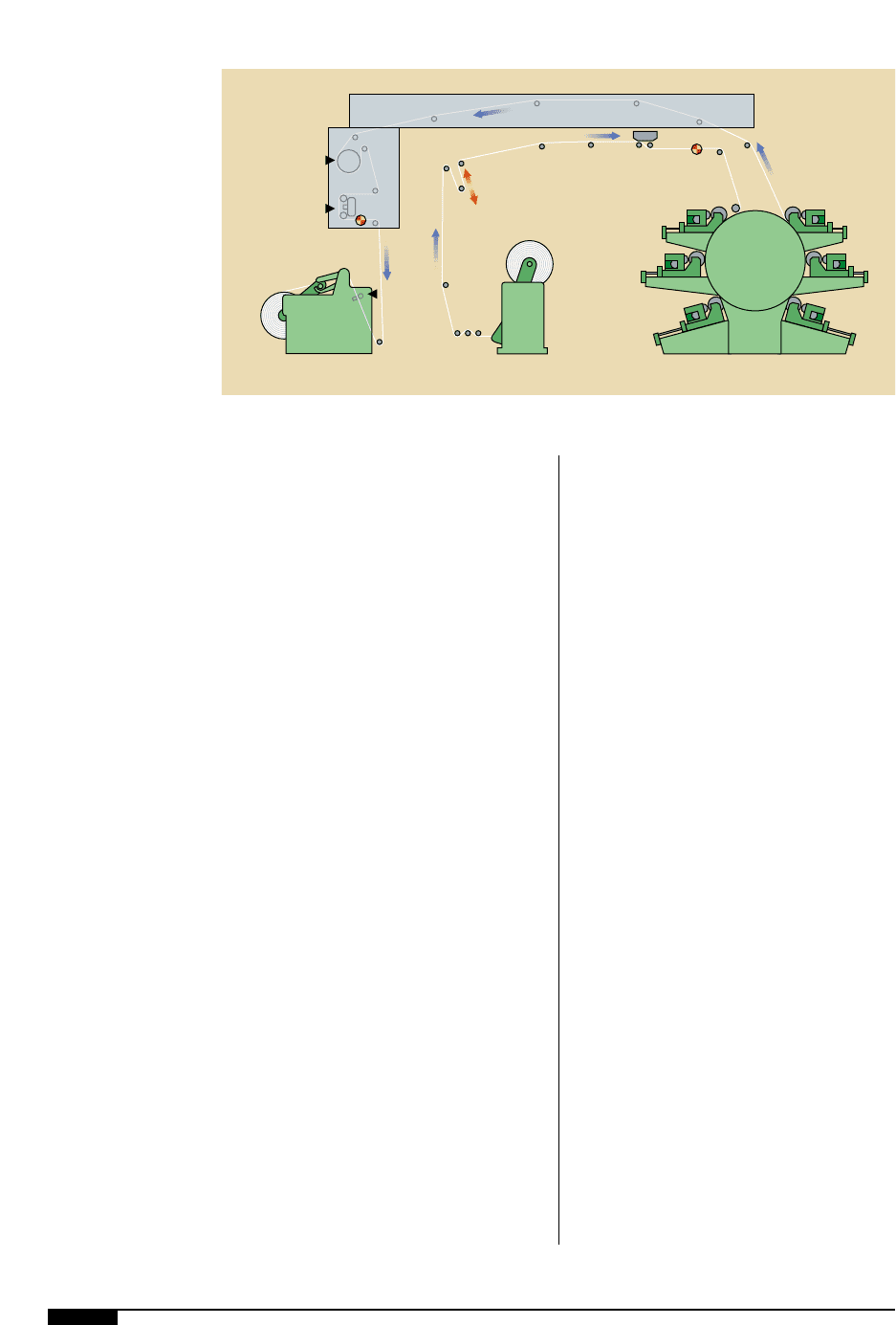
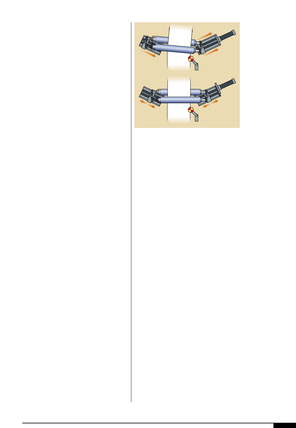
INTERMEDIATE WEB GUIDES
If there are long spans between the unwind
and first print station, it may be desirable to
install an intermediate web guide immediately
ahead of the first print station, either in lieu of
or in addition to the unwind guide (Figure
3^
).
This intermediate guide can correct for any
web position errors that may occur in spans
between the unwind and the first print station.
Intermediate guiding devices generally fall
into two categories. The first is a steering
guide, which is a roller having accurate
motion (in the plane of web travel) about an
instant center located several web widths
ahead of the guide. The second type of inter-
mediate guide is a displacement guide, or off-
Oven
Unwind
Rewind
Slitting
Sensor
Intermediate
Web Guide
Central
Impression
Cylinder
Chill Roll
Sensor
Offset
Pivot
Guide
3^
3^
Installing an inter-
mediate web guide
immediately ahead of
the first print station,
either in lieu of or in
addition to, the unwind
guide, there is a great
distance between the
unwind and the first
print station.
PRESSES AND PRESS EQUIPMENT 67
set-pivot guide, which is a two-roll assembly,
the rollers of which are pivoted about a line
tangent to the face of the entry roll.
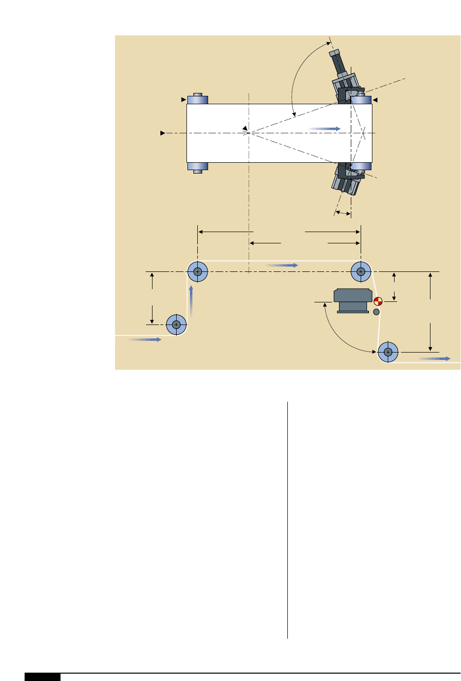
Steering Guides
Steering-type intermediate guides, as seen
in Figure
3&
, have been used with great suc-
cess for many years. A steering guide pro-
vides web position correction by bending
the web through a long entering span. This
type of application, however, requires a long,
free entry span to distribute the stress dis-
tortions caused by the guide motion. The
span requirement is also a function of the
mechanical properties of the web.
When web materials of unusually high
stiffness or very thin and extensible materi-
als at very low tensions are encountered, it
becomes desirable to employ offset pivot-
type guides as opposed to steering guides to
minimize the web stress distribution in limit-
ed-guide entry and exit spans. An offset-
pivot guide with a large dimension between
the two guide rollers requires only short
entry- and exit-span dimensions. Therefore,
it can be installed under the dryer bridge or
below a viewing platform for the web scan-
ner prior to the rewind. The range of materi-
al types to be run on a press and the press
geometry and auxiliary equipment layout,
combined with various guide arrangements
and costs, determine the choice of specific
guide types and locations.
Steering guides are mechanical devices
using one or more rollers rotating about a
remote center of rotation located up-
stream from the device. The center of ro-
tation is also known as the instant center.
The device steers the web in the entering
span of the guide by changing the angle of
the roll relative to the centerline of the
machine. The angular change corrects
steady-state errors, whereas the translation
due to the remote instant center corrects
transient errors.
The steering guide consists of a single or
pair of fixed raceway bases and a moving
structure. The moving structure, sometimes
referred to as the pivot carrier, holds the roll
and rotates about the remote center of rota-
tion. The roller is attached to pivot brackets,
which are attached to the pivot carrier.
The center of rotation is generally located
two-thirds to three-quarters the length of the
entering span ahead of the guide roller. This
location provides satisfactory dynamic char-
acteristics. The angle of rotation of the guide
roller is small, usually less than 3°. For most
steering guides, the location of the center of
rotation can be adjusted by positioning the
base at the correct angle during installation.
The span immediately upstream of the
guide is known as the entry span. The span
upstream of the entry span is known as the
pre-entry span. The relative length of these
two spans is important and will be explained
later. The last fixed roller prior to the guide
roller is referred to as the entry roller.
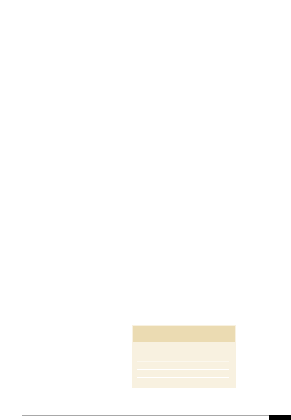
Steering Guide Operation
The plane of motion of the steering guide
is normally parallel to the plane of the enter-
ing span (Figure
3*
). If the web on the entry
roller is displaced from the desired guide
point, the pivot carrier rotates, causing the
web to be repositioned to the desired guide
point. As the pivot carrier rotates, the web is
bent laterally. The greatest bending occurs
Raceway
Assembly
Sensor
3&
3&
Steering-type
intermediate guides
provide web position
correction by bending
the web through a long
entering span.
3*
A typical installation for a
steering guide operation.
68 FLEXOGRAPHY: PRINCIPLES & PRACTICES
90°
Fixed
Entering
Idler
L (Entering Span)
Pre-Entry
Span
L
1
(2/3 to 3/4 L)
L
2
Exiting
Span
X
2
Guide Roller
Approximately 5° to 25°
Sensor
Deadbar
or Support
Roller
Center of Rotation
of Guide Roll
(Instant Center)
Web Travel
Centerline
of Machine
and Guide
Assembly
90°
3*
as the web exits the entry roller. The exit is
where the highest stress distortion occurs.
At the point of critical rotation, the stress
on one edge will be zero. The stress on the
other edge will be approximately 13 times
the web’s average stress. This lateral bending
of the web, and the associated stress distor-
tion, is the primary reason the steering guide
requires a long entry span. If the rotation of
the steering guide exceeds the critical angle,
the stress on one edge can become negative,
meaning it has a loose edge. The stress on the
other edge increases to compensate for the
loose edge. The net tension in the web will
remain constant, but if less web width is
under tension, then web stress becomes
higher. The loose edge can result in troughs
and/or wrinkles being formed in the web.
The web-entering span ideally should be
parallel to the guide plane of motion. In a
worst case scenario, the web plane of
motion should be no greater than 30° off the
guide plane of motion.
Instant Center Location. The location of the
center of rotation is very important in
obtaining stability in the control system.
The center of rotation is ideally two-thirds
to three-quarters the length of the entry
span upstream of the guide roller. If the cen-
ter of rotation is less than ideal, the guide
becomes over-steered. The magnitude of
over-steering is inversely related to the dis-
tance the center of rotation is located
upstream. As over-steering increases, the
guide control system becomes more and
more unstable until the system oscillates
PRESSES AND PRESS EQUIPMENT 69
constantly, causing the guide to induce
more error than it is correcting.
Entry Spans. The length of the pre-entry span
should be shorter than the length of the
entry span. If the pre-entry span is equal to
the entry span or longer, the stress distor-
tions in the entry span can transfer across
the entry roller into the pre-entry span.
In the pre-entry span, stress distortions will
cause a movement in the web, inducing error.
The guide will then try to correct the greater
error, causing even more error. The end result
will be the guide bottoms trying to correct the
amplified error. This chain of events is known
as a pre-entry span condition. Keeping the
pre-entry span shorter than the entry span
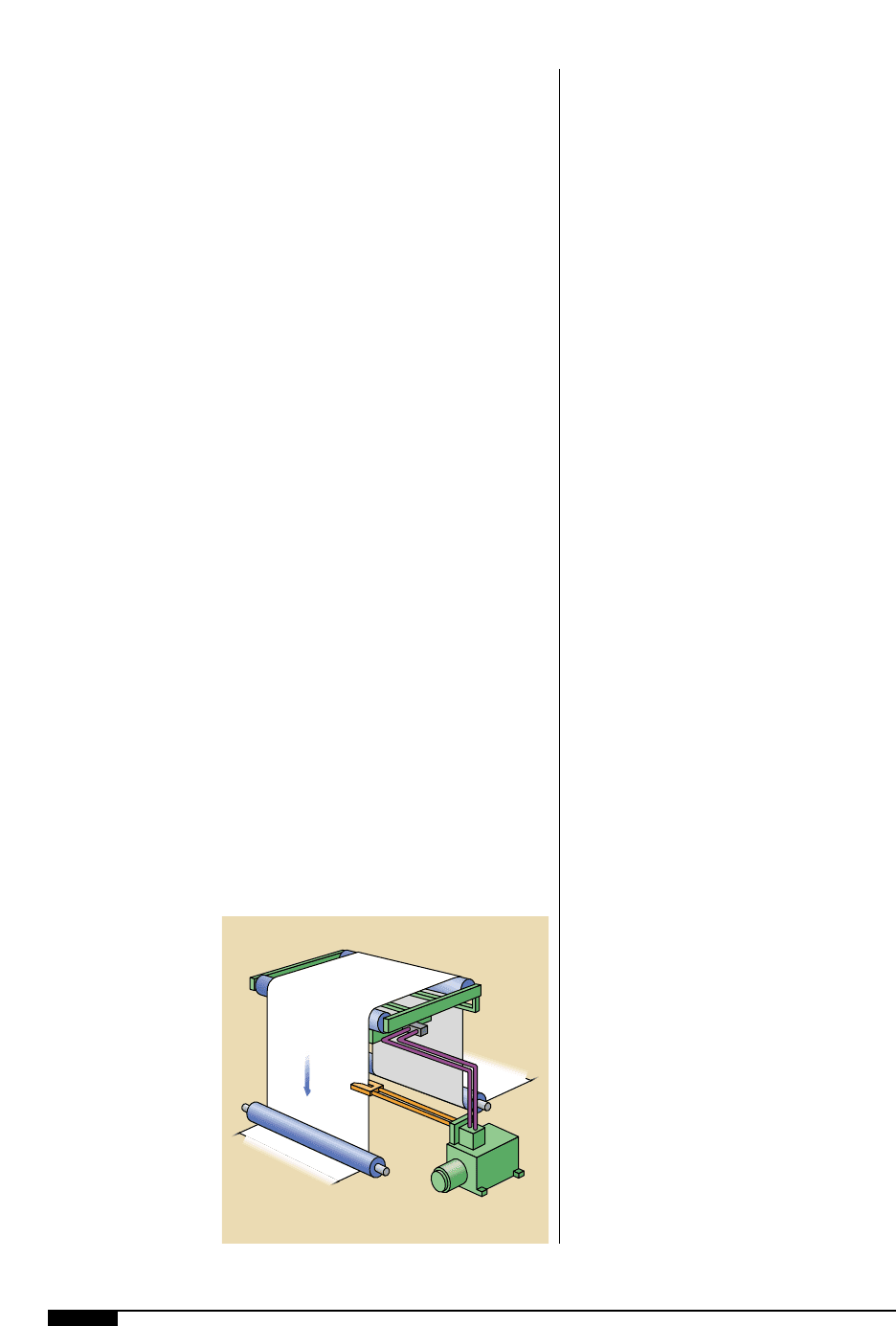
prevents this problem. The lengths of the typ-
ical entering spans expressed in web widths
for normal corrections are shown in Table 5.
The required correcting capabilities of a
steering guide can be determined by the
equation:
C 9T(L/W)
2
/tE
Where:
C = guide correction (inches, mm)
E = modulus of elasticity
(psi, Newtons/mm
2
)
L = length of entry span (inches, mm)
T = tension (pounds, Newtons)
t = web thickness (inches, mm)
W = maximum web width (inches, mm)
Web Plane. The plane of the web in the exit
span of the steering guide ideally should be
perpendicular to the guide plane of motion.
This arrangement will keep the stresses in
the exit span to acceptable levels. In this
case, the web in the exit span is twisted.
In some cases, a steering guide with a
straight through-pass is used. The plane of
the exit span is then parallel to the guide
plane of motion. These installations work,
but with increased stress distortions in the
exit span and loss of guide accuracy due to
the bending of the web in the exit span. This
loss of accuracy is known as residual error
and can be as much as 20% of the incoming
error, depending on the material and the
length of the exit span.
The equation for exit span length limits the
edge stress amplification to three times the
average stress. This limit prevents possible
web damage. As a rule, if material properties
are not known or if the calculated exit span is
less than one-half the web width, the exiting
span should be greater than one-half the web
width in length. This span reduces the possi-
bility of the steering guide inducing wrinkles
into the web.
In the case of stiff webs, the previous equa-
tions should be used to determine the mini-
mum length of the entering and exiting spans.
Steering Guide Selection
To select the proper steering guide
model, or to determine the actual steering
load capacity of the guide, the following
application parameters must be known:
• web wrap style;
• modulus of elasticity of the
web material;
• maximum web width;
• maximum web tension;
• maximum web thickness;
• web error;
• roller diameter;
• roller face length;
• guide entry span; and
• exit span length.
To prevent the steering guide from
inducing wrinkles in the web, it is recom-
Table 5
MATERIAL ENTRY SPAN IN WEB WIDTHS
■ WOVEN TEXTILES 1 to 2
■ PLASTIC FILMS 1.5 to 3
■ PAPER AND PAPERBOARD 2 to 5
■ METALS 10 to 390
ENTRY SPANS
mended that the exit span be greater than
one-half the maximum web width.
Offset Pivot Guides
An offset pivot guide (OPG), shown in
Figure
3(
, is a mechanical device used to
correct the lateral error in a web of material
as it runs through a process. The OPG cor-
rects the error by displacing the web
between the entry span and the exit span of
the guide. It is a displacement-type guide that
provides web position correction with mini-
mum entry and exit span requirements.
Designed with parallel rollers, the guide piv-
ots such that the web is twisted, thus mini-
mizing web stress. This design allows an
OPG to be used in the least amount of space.
The offset pivot guide consists of a fixed
base and a pivoting structure with one or
more rollers. The pivoting structure, referred
to as a pivot carrier, rotates about a fixed,
imaginary point called the pivot point. The
angle of rotation is limited to 7.5° maximum.
The point of rotation is ideally in the plane of
the entry span or within 10% of the guide
span of the entry span plane.
OPG Operation. If the web on the entering
roller is displaced from the desired guide
point, the pivot carrier will rotate, causing the
web to be repositioned to the desired guide
point. As the pivot carrier rotates, the web in
the entering and exiting spans is twisted. This
twisting causes the stress in the web to be
redistributed so the stresses are higher at the
web edges than in the center of the web.
The web should enter the OPG perpendic-
ular to the plane of motion of the OPG. The
plane of motion is the plane that the pivot
carrier rotates in. Webs entering the OPG at
angles other than perpendicular to the plane
of motion cause an increase in stress distor-
tions and detrimental steering effects in the
web. These steering effects can cause insta-
bilities in the guide control loop or lead to
reduced guiding accuracy, as well as stress
distortions that could damage the web.
When the pivot carrier is in a centered
position, it does not influence the lateral
position of the web because the rollers on
the pivot carrier are parallel to the other
rollers in the process line.
Different models of OPGs are available for
different web widths, web tensions and roller
diameters. The guide span (the distance from
outside of the entering guide roller face to
the outside of the exiting guide roller face)
and the roller face lengths are a variable fea-
ture for each model. While the guide span
should ideally be equal to the web width, it
should never be less than one-half the web
width.
As a rule, if the material properties are not
known or if the calculated entry/exit span is
less than one-half the web width, the entering
and exiting spans should be made greater
than one-half the web width in length. This
precaution reduces the possibility of the
OPG inducing wrinkles into the web.
OPG Selection. To select the proper OPG
model and determine the guide angle, correct
exit and entry spans, the following applica-
tion parameters must be known:
• guide correction;
• modulus of elasticity;
• length of entry span ;
• maximum tension;
3(
The offset pivot guide
is a mechanical device
used to correct the
lateral error in a web
of material as it runs
through a process.
Economy of space is a
major advamtage of an
OPG.
70 FLEXOGRAPHY: PRINCIPLES & PRACTICES
3(
PRESSES AND PRESS EQUIPMENT 71
• web thickness;
• maximum web width ;
• roller diameter;
• roller face length;
• guide span;
• base mounting dimension; and
• wrap style and base mounting style.
The actual load capacity of an OPG
depends greatly on the guide span, roller face
length and wrap style.
REWIND GUIDING
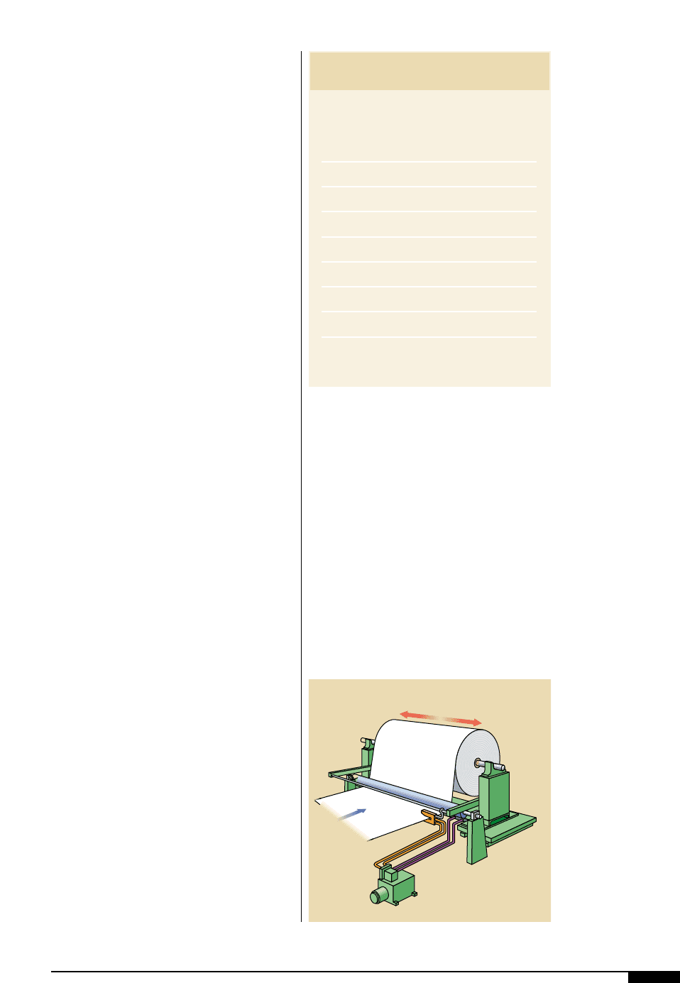
Rewind guiding (Figure
4)
) is not truly lat-
eral control of a web. Rewind guiding is actu-
ally a chasing control system. At the rewind,
guiding is accomplished by attaching the sen-
sor to the rewind stand and shifting the stand
to chase the web as it comes from the press.
In actuality, this is not web guiding at all but,
rather, merely positioning the rewinding
mandrel in such a way as to follow the nor-
mal wandering of the web so that its edge is
maintained in fixed, lateral relationship to
the rewinding mandrel at all times.
A fixed idler roller between the moving sen-
sor and rewind stand isolates the web from
stand motion and provides for a constant web
plane at the point of sensing. The same con-
siderations regarding mechanical and
hydraulic resonant frequencies apply to
rewind guiding as to unwind guiding. In addi-
tion, however, care must be exercised in
designing the support for the sensor so there
is sufficient rigidity to avoid flexure and
mechanical resonance in this part of the
equipment. Factors to consider in selecting
an unwind/rewind stand are shown in Table 6.
Rewind Operation
The rewinding roll is positioned to align
the edge of the rewind roll to the edge of the
approaching web. The sensor is located just
ahead of the last fixed idler in the machine
and is typically attached to the rewind stand
with a mechanical arm. The operator either
manually or automatically positions the sen-
sor at the edge of the web being chased. The
sensor chases the edge of the web and, as a
result, the rewind control system then caus-
es the rewind stand to shift laterally as the
web tracks laterally, resulting in a roll of
material with a straight edge.
Systems are available that do not require
the sensor to be mounted to an arm attached
to the rewind stand. Instead, the sensor is
4)
4)
In a typical rewind edge
guiding, the rewinding
mandrel is positioned in
such a way as to follow
the normal wandering of
the web, so that its edge
is maintained in a fixed,
lateral relationship to
the rewinding mandrel
at all times.
Table 6
To select the proper stand, the following appli-
cation parameters must be known:
1. Web material.
2. Maximum web width.
3. Maximum tension.
4. Maximum lateral shift required.
5. Maximum line speed.
6. Maximum roll weight.
7. Maximum roll diameter.
8. Maximum weight of the stand.
9. Coefficient of friction for the slider
bearings.
UNWIND/REWIND
STAND SELECTION

72 FLEXOGRAPHY: PRINCIPLES & PRACTICES
electronically connected to the rewind stand.
The rewind stand is generally positioned so
there is approximately one web width from
the last fixed idler.
In rewind guiding, if the sensor is located
downstream of the last fixed idler or the web
does not have sufficient frictional engagement
with the last fixed idler, a roll with a ragged
edge will be wound. Another problem often
seen in rewound rolls is telescoped wraps.
The guiding system is often blamed for this
defect, when in reality, the roll was not wound
with sufficient tension to prevent lateral slip-
page of one or more layers in the wound roll.
This defect often occurs many layers deep in
the wrap being applied, during winding or
even days after the roll is removed.
