FTA (изд-во). Flexography: Principles And Practices. Vol.1-6
Подождите немного. Документ загружается.


ished product roll and to keep air from being
trapped between the plies of material, which
will prevent telescoping. In addition, flying-
splice rewind units generally have secondary
(or follower) rider rolls. These secondary
rolls ride against the rolls throughout the
rewinding and splicing sequence. When the
rewind arms of the primary rider roll lose
contact with a roll that is in the final state of
being wound, the follower rider roll contin-
ues pressing against the full roll to prevent
air entrapment and telescoping. The secon-
dary rider rolls can be either spring, hydrau-
lic or pneumatically loaded.
Flying Splice. The flying-splice rewind uses
the same basic center-winding principle, but
has two core shafts mounted on a turret. The
drive and auxiliary equipment are more
sophisticated and aim to splice at full operat-
ing speeds. Normally, each shaft is driven
through a slipping clutch and/or separate,
direct drive motors to permit speed control
of each shaft. Center-shaft, flying-splice units
have become the most popular and widely
used winders today, especially in the pro-
cessing of extensible films and packaging
materials.
Unloading. Roll unloading equipment is
available in the form of hydraulic or pneu-
matic roll-lowering arms for the single-posi-
tion winder. Floor dollies or overhead hoists
are normally used for unloading the rolls
from either the center-shaft or flying-splice
rewind units.
Slitting. Roll slitting on center winders has
grown in use. Score and razor-blade slitting
attachments are available as auxiliary equip-
ment. Shear slitting is also used in some
instances where materials call for it. A
spreader bar, driven expander roll or slatted
expander roll is used after slitting to prevent
web interleaving.
Web Guide. Edge guiding on rewinds gener-
ally employs one of two approaches. One is
to independently guide the web to the wind-
ing roll; the other is to side shift the rewind-
ing unit to “chase” the web edge. If the
winder is quite large, the provisions for
shifting it may be relatively expensive com-
pared with an independent guide ahead of a
stationary rewind. Recently, on presses with
web-scanning inspection devices ahead of
the rewind unit, an independent web guide
has been installed beneath the scanner
viewing platform to maintain web alignment
through the viewing section.
Splicing. Semi-automatic or automatic splic-
ing attachments can be fitted to turret-type
rewind units. The operator starts the splic-
ing sequence by rotating the turret to a pre-
set splicing position. When the core shaft is
running at or close to the printed web speed,
the operator manually makes a splice by cut-
ting the web while simultaneously pushing it
against the new, pre-glued or taped core.
This same sequence has been fully automat-
ed, thanks to hydraulic or pneumatic cylin-
der-actuated cut-off mechanisms and elec-
tric sequence controls.
Large-roll diameter flying-splice units are
required for additional footage when pro-
cessing laminates. These units allow the han-
dling of larger rolls and further reduce down-
time. Along with the larger diameter rolls,
core sizes are also increasing in order to keep
the roll buildup ratio more in line with the
capabilities of present rewind drives.
REWIND TENSION SYSTEMS
There are two basic tension-control sys-
tems: constant tension and taper tension. In
a constant-tension rewind system, the ten-
sion in the sheet being wound is the same on
the first wrap at the core as at the last wrap
on the roll. In a taper system, the tension in
the last wind of the roll is less than the ten-
sion in the web at the core. For instance, if a
web experiences two pounds of tension per
linear inch at the core and finishes winding
the roll at one pound per linear inch, the ten-
sion experienced is referred to as a 2:1 taper.
PRESSES AND PRESS EQUIPMENT 53
54 FLEXOGRAPHY: PRINCIPLES & PRACTICES
A center rewind unit can offer either con-
stant or taper tension. A drum rewind unit
offers only constant tension. Since most
flexographic presses use center-shaft rewind
units, more attention will be given to these
tension systems.
A good rewind tension system should be
capable of winding rolls with straight edges
and uniform density, while preserving the
accuracy of register and repeat length in the
print stations. To accomplish these require-
ments, the unit must be able to rapidly and
accurately follow the acceleration and decel-
eration of the printing press, compensate for
change in the diameter of the winding roll,
and be able to make rapid speed transfers
when used with flying-splice rewind units.
The drive must be able to handle wide or nar-
row webs; flexible, stiff or stretchable mate-
rials; and, in some cases, perforated webs.
POWER REQUIREMENT
Specifying a rewind system and sizing the
rewind motors is a job for the press design-
er. However, it is useful to know the para-
meters and how to apply them when adapt-
ing a press to suit a new substrate applica-
tion. The following are some of the factors
used to determine the rewind horsepower
needed: line speed expressed in feet per
minute; core tension expressed in pounds
per web inch; web width expressed in inch-
es; the mathematical horsepower constant;
and the ratio of the full-roll diameter over
the core diameter.
Two other factors should also be consid-
ered. The first is taper, which is selected
core tension divided by full roll tension, if
taper winding is required. The other is an
experience factor, and this has to do with the
windage and friction losses that are present
in the various mechanical components of
any particular rewind stand.
In setting up the various formulae to size a
particular winder drive, the following para-
meters must be known:
• line speed (feet/minute);
• line acceleration or speed change over
the time taken (feet/minute
2
);
• core tension (pounds/inch);
• web width (inches);
• taper tension when used (core tension/
full roll tension);
• core diameter (inches);
• full roll diameter (inches);
• full roll weight; and
• experience factor for rewind.
The general equation for determining the
approximate rewind drive horsepower is:
HORSE
2π TORQUE REVOLUTIONS/MINUTE
POWER
33,000
WINDER
TENSION
WIDTH
ROLL
TORQUE DIAMETER
2
CORE
Line Speed
RPM
π ROLL DIAMETER
Winding horsepower for a constant line
speed therefore is directly proportional to
web tension, web width and line speed and
is independent of roll diameter. However,
whenever line speed is changed, the inertia
of the wound roll must be overcome either
by a braking system to slow the roll or addi-
tional horsepower to accelerate.
ROLL
ROLL
ROLL
CORE
INERTIA MASS DIAMETER
2
DIAMETER
2
8
ROLL
2 LINE SPEED CHANGE
ACCELERATION
ROLL DIAMETER
INERTIA
ROLL
ROLL
TORQUE INERTIA ACCELERATION
For any given roll diameter and line speed
acceleration, winding torque is proportional
to the roll diameter, and roll acceleration is
inversely proportional to the roll diameter.
Therefore, the horsepower required to over-
come the roll inertia torque on press start-up
[]
or speed change depends largely on the time
it takes to run the press up to speed and is
proportional to the roll diameter.
Many materials wind best by taper ten-
sion; some wind best by constant tension. A
representative list of materials and their sug-
gested winding tensions and recommended
winding method is shown in Table 3. A web
wound by either method must be controlled
by a sensing device.
Constant Tension
The most commonly used controller for a
constant-tension winding system is a dancer
roll. The dancer may be loaded by weights,
air or a torque motor. A typical weight-loaded
dancer system was previously described in
the section on dancer rollers (Figure
2$
).
Any movement of the dancer roll signals the
rewind drive to speed up or slow down,
maintaining a given dancer-roll position.
Another method to control the rewind drive
is a load cell transducer.
The rewind motor can either be a DC or a
constant-speed AC motor fitted with an
eddy-current clutch. Direct current motors
are more expensive, but because of their
superior performance, are now virtually
standard on new equipment.
Taper Tension
The controller for a taper tension wind can
be set up in several ways. One method is by
an electronic controller using solid-state cir-
PRESSES AND PRESS EQUIPMENT 55
Table 3
MATERIAL TENSION PREFERRED WINDING METHOD
(lb per mil per inch of width)
Aluminum Foils 0.5 to 0.15 Taper 1.5 to 1
Cellophanes 0.5 Taper 1.25 to 1
Cellulose Acetate 0.25 to 0.5 Taper 1.25 to 1
Ethyl Cellulose 0.5 Taper 1.25 to 1
Glassine 1.0 to 2.0 Taper 1.1 to 1
Methyl Cellulose 0.5 Taper 1.25 to 1
Polyester 0.5 to 1.0 Constant or Taper 1.25 to 1
Polyethylene 0.2 Constant or Taper 1.25 to 1
Polypropylene 0.187 to 0.25 Constant or Taper 1.25 to 1
Polystyrene 1.0 Taper
Rubber Hydrochloride 0.06 to 0.25 Constant
Vinyl Chloride Copolymers 0.06 to 0.187 Constant
Vinylindene Chloride Copolymers 0.06 to 0.187 Constant
Paper & Laminates ( per inch of width)
20# 0.5 to 1.0 Taper 1.5 to 1
40# 1.0 to 2.0 Taper 1.5 to 1
50# 1.25 to 2.5 Taper 1.5 to 1
60# 1.5 to 3.0 Taper 1.5 to 1
80# 2.0 to 4.0 Taper 2 to 1
85# 2.0 to 4.3 Taper 2 to 1
REWIND TENSION RANGES
56 FLEXOGRAPHY: PRINCIPLES & PRACTICES
cuitry. The controller receives two electrical
signals from the main drive system. One sig-
nal must be proportional to line speed and
the second proportional to acceleration.
The signal proportional to line speed is
usually obtained from a tachometer genera-
tor mounted on the main drive. A signal pro-
portional to the main drive acceleration is
obtained from the main-drive control sys-
tem. The controller regulates the winder
drive shaft output horsepower, whether it
be a DC motor or an eddy-current clutch.
Adjustments are provided in the controller
to allow tension to be decreased as the roll
size increases, providing a taper tension.
With this type of equipment a wide range of
tension patterns may be obtained with a sin-
gle-winder drive and controller.
The operator can vary the tension level to
accommodate different material thickness
and width combinations. The operator first
sets a tension value; the regulator will
decrease this value according to the taper
pattern programmed into its system. It is
possible to program several different tapers
into the system and have an operator selec-
tor switch to choose the taper pattern
desired during any given run. Since this type
of rewind drive only develops torque, it
does not know which portion goes into fric-
tion and windage and which portion goes to
the web, hence the experience level of the
press operator is important.
As mentioned in the rewind horsepower
formula, the drive manufacturer must take
operator experience into account in adjust-
ing for windage and friction losses when siz-
ing the rewind motor. In the previously dis-
cussed alternative dancer-roll system, the
tension in the web is only a function of the
loading of the dancer roll and, therefore,
friction, windage and inertia do not affect
the drive operation.
Another type of controller system is the
force transducer ( Figure
1%
). It is similar to
the dancer-position drive, except that the
dancer roll is replaced with a fixed roll cou-
pled to a load cell arrangement, sometimes
called a strain-gauge amplifier. This system
has very precise and linear deflection-ver-
sus-load characteristics. Consequently, the
deflection of this load cell is directly pro-
portional to the web tension exerted upon
it. A small deflection (0.001") can cover the
entire tension range desired. This sensing
system is therefore very responsive and
accurate. It has the ability to readily adjust
taper with an electrical potentiometer
(operator’s tension setter) and it provides a
readout of the tension on a calibrated meter.
Table 4
SINGLE DUAL
MOTOR MOTOR CONTROL TIE-IN W/ TENSION ADJUSTMENT
DRIVE TYPE COST COST COMPLEXITY MAIN DRIVE RANGE TAPER
■ TORQUE REGULATED (TR) 130% 210% Medium Yes Medium
1
Yes
(Taper Tension)
■ DANCER POSITION (DP) 100% 180% Low No Medium
2
No
(Constant Tension)
■ CELLULOSE ACETATE 170% 240% High Yes Wide Yes (in TR mode)
■ FORCE TRANSDUCER 200% 330% High No Wide
3
Yes
(Load Cell)
1
Better at high end.
2
Better at low end.
3
Direct reading.
REWIND DRIVE CHARACTERISTICS

Since this system has no material storage,
there is nothing to absorb the tension
shocks resulting from out-of-round rolls,
splicing, or other irregularities. Compen-
sating systems are provided in its design to
handle these conditions.
Table 4 sums up the characteristics of the
drives that have been discussed. The
dancer-position drive is used as a base point
or the 100% reference line. For different dri-
ves, the relative cost, control complexity,
tie-in with the main drive, tension range and
adjustable taper have been compared.
The dancer-position system has low con-
trol complexity, medium tension range and
does a good job of winding materials requir-
ing low tensions. The taper-drive system has
a medium tension range and does a better
job of winding materials requiring higher
tensions. It requires a tie-in with the main
drive, has medium control complexity and
costs more than the dancer-position system.
A combination system of both taper and
dancer position is commonly used, allowing
for a wider range of tension values. In this
case, when winding heavier materials, the
dancer roll is bypassed and the drive winds
in the taper mode. When winding lighter
materials, the dancer roll may be used and
the control is then electrically transferred to
the dancer-position mode.
The force transducer system has a wide
tension range and features a direct tension
readout. This system does not require a tie-in
with the main drive and is readily adjustable
to taper controls. The system rates a “medi-
um” in complexity and expense.
Rewind drives, in the case of flying-splice
systems, can be equipped with either single
or dual motors. Dual motor drives have sev-
eral benefits, and individual core-shaft elec-
trical braking is available. No auxiliary core-
shaft clutches are required, and it’s easy to
get a very efficient, high-speed transfer from
the full roll to the empty core. On single-
motor systems tied into flying-splice rewind
units, it is necessary to use clutches to
engage the drive motor to each of the core
shafts. Although it is possible to speed match
the empty core to the line speed by “slipping”
the full-roll clutch, this method is not as reli-
able or as smooth as the two-motor system.
For these reasons, two-motor systems are
now standard on most modern equipment.
SURFACE-REWIND
TENSION SYSTEMS
The tension system used in most surface
rewind units is simpler than those just dis-
cussed. The double-drum or single-drum
surface rewind is normally geared to the
main drive so that the winding drums are
driving at a speed proportional to the line
speed. In order to establish a given tension,
a variable-speed drive is usually employed.
The operator adjusts the rewind to run
faster than the press. The material slippage
on the winding drums establishes the ten-
sion.
In certain applications, surface winders
are driven by a follower-type DC or eddy-
current, clutch-and-drive motor combina-
tion. Again, an operator sets the basic wind-
ing tension on one winding drum, while
another drum continually tries to tighten the
roll. The differential speed between winding
drums is usually obtained by gearing arrange-
ments. However, twin DC motors have been
used. The operator can then select a different
speed setting between the winding drums.
This approach allows a wide range of roll
hardness, depending on the difference in the
speed settings of the two drums.
With a single-drum system, there is no dif-
ferential or tightening effect. The winding
tension is set by the operator through the
mechanical or electrical speed controls.
PRESSES AND PRESS EQUIPMENT 57

58 FLEXOGRAPHY: PRINCIPLES & PRACTICES
Pneumatic Shafts
and Chucks
W
henever there is a roll or
web, regardless of the
material, it has to be
unwound and usually
rewound. In most cases
the roll has a core of
some type, which could be paper/fiber,
metal, plastic or wood, that has to be held
securely to provide rewinding tension or
braking torque. There are a variety of man-
drels, shafts and chucks in use and most are
mechanically or pneumatically operated.
Mechanical shafts and chucks have been
widely used for conventional web handling
operations and are well-known in the field.
Pneumatically-operated shafts and chucks,
because of their simplicity and reliability, are
accepted as standard by engineers, produc-
tion supervisors and maintenance personnel
knowledgeable in manufacturing and con-
verting operations where web materials are
being processed. This next section will
explain the operation and application of
pneumatic shafts – more commonly called
air shafts – and chucks.
AIR SHAFTS
Air shafts are used for both conventional
and more demanding applications. They
offer many advantages over the older
mechanical shafts mainly because of their
light weight and simplicity of operation. In
addition, a high strength-to-weight ratio
results in minimum deflection, and the abil-
ity to maintain a full grip across the entire
length of the core or roll face allows air
shafts to handle very high torque. Narrower
rolls can be handled because of low deflec-
tion from loads concentrated near the cen-
ter. Low maintenance and easy in-plant
repair procedures contribute to the popular-
ity and extensive use of air shafts.
Although the air-shaft design is basically
simple, a variety of styles are available and
each shaft is custom-made to suit specific
requirements of an application. Each of
these types is designed around one basic
principle, i.e., a metal tubular bar acts as the
load-carrying member. The body of the shaft
has a number of drilled holes or slots into
which are fitted buttons or lugs backed with
steel pressure flanges. Upon introduction of
air into the shaft, an internal air bladder
expands and forces the buttons or lugs radi-
ally outward until the inside diameter of the
core is securely gripped along its full length.
The internal air bladder is made of a tear-
resistant neoprene or similar material and
has bonded ends or metal fittings to form an
airtight flexible chamber. Air pressure of
approximately 80 psi is necessary to ensure
that the outward thrust is sufficient to grip
the core. When the air is released, the shaft
deflates, causing the spring-loaded buttons
or lugs to retract below the outside surface
of the body and allow fast shaft removal.
There are five basic types of air shafts:
large-button, lug, small-button, leaf and fiber-
glass-sleeve (Figure
2*
). The best applica-
tions are described in the following para-
graphs.
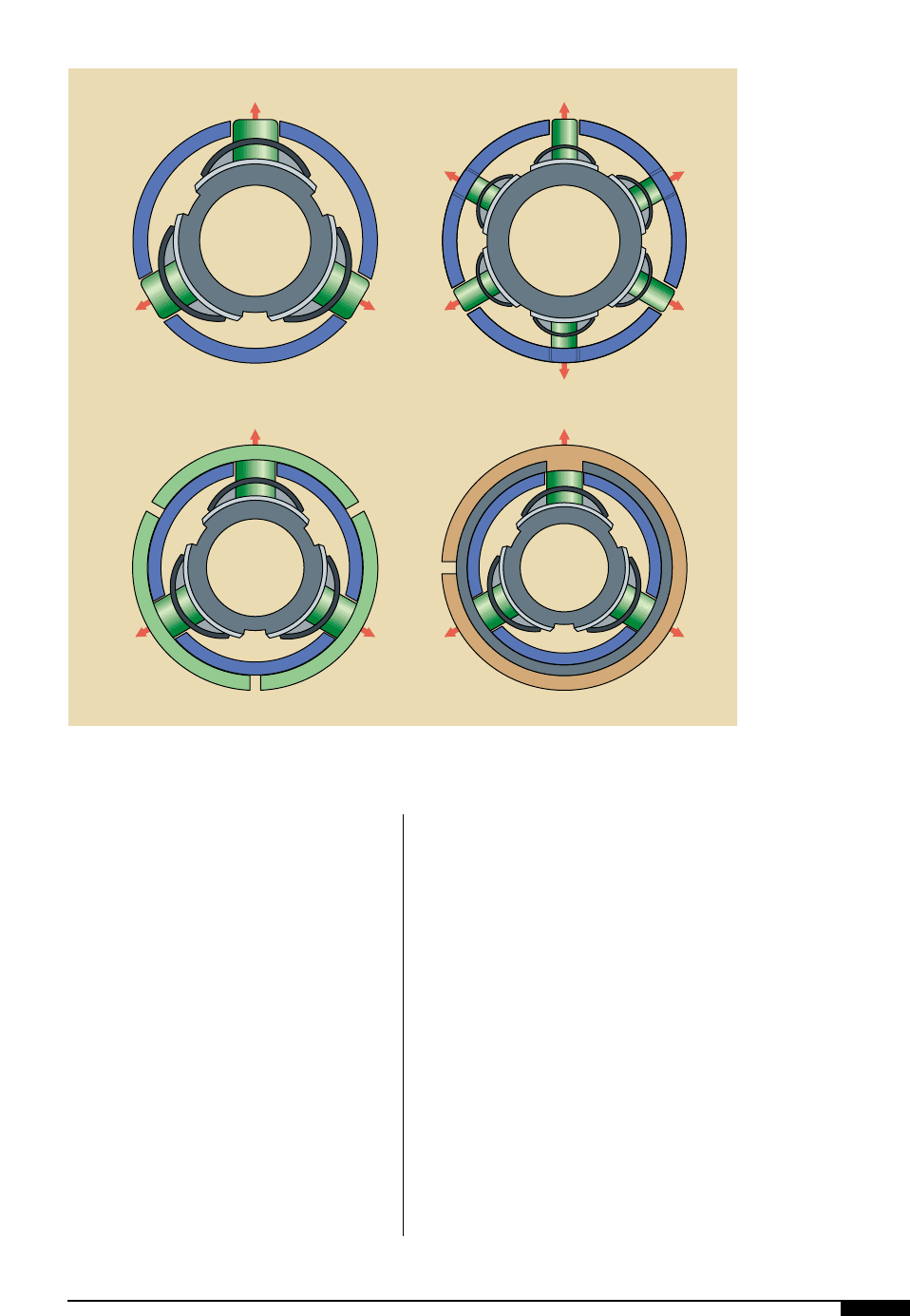
Large Button Type. For rugged, heavy duty
standard core winding or unwinding. Big
buttons 0.625" in diameter are spaced 1.75"
apart in multiple rows.
Lug Type. The lug type of air shaft is similar
to the large-button type, but with bars 0.25"
wide by 3" long instead of buttons.
Small Button Type. For stacked or multiple
cores when slitting and rewinding narrow
webs. Small buttons 0.375" in diameter are
spaced 0.75” apart in multiple rows. This
shaft has the capability of gripping individ-
ual narrow cores stacked on the shaft even if
the core tolerances vary from one core to
the next.
Leaf Type. For rugged heavy-duty coreless
winding or where thin walled cores are
used, this type provides a continuous grip-
ping action throughout the entire expand-
ing face, making it suitable for winding
multiple rolls or rolls without cores.
Fiberglass-Sleeve Type. A variation of the leaf
type, this air shaft is used when light-han-
dling weight is of prime importance. Two
fiberglass sleeves used in lieu of leaves and
in conjunction with a high tensile aluminum-
shaft body account for the weight saving and
make for a lightweight rugged unit.
SPECIAL AIR SHAFTS
There are many specially designed models
of air shafts for specific requirements. Four
unique and popular types are described
PRESSES AND PRESS EQUIPMENT 59
2*
Four of the five basic
types of air shaffts. The
large button type is best
used with heavy duty
winding and unwinding,
while the small button
type is bet used with
multiple cores. The leaf
type is effective in core-
less windings, while the
fiberglass-sleeve type is
used an an altenative to
the leaf type in light-
weight applications.
Large Button Small Button
Leaf Fiberglass Sleeve
2*
60 FLEXOGRAPHY: PRINCIPLES & PRACTICES
below. However, thousands more have been
built for just about every conceivable wind-
ing or unwind operation and it would be
impossible to describe each one. Torque fig-
ures and additional engineering data are
available from manufacturers. In general, air
shafts have a superior performance record
versus mechanical shafts.
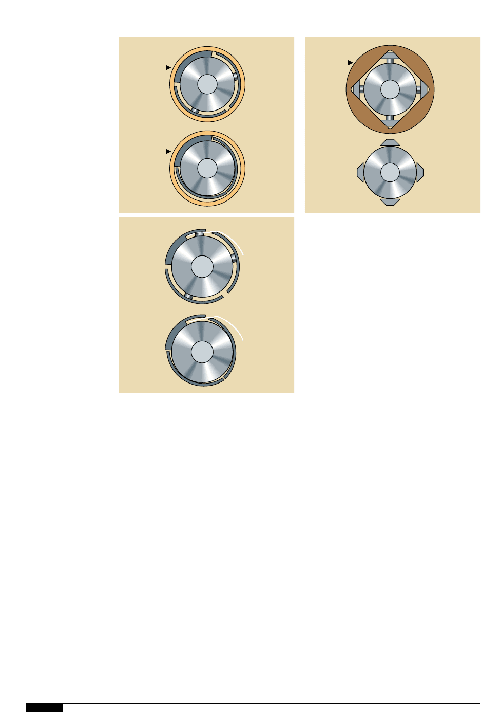
Fixed Leaf Type. This shaft gives maximum
concentricity in close-tolerance cores. One
leaf is located and secured in the fixed posi-
tion, its radius matching the inside diameter
of the core (Figure
2(
). The remaining
leaves expand and retract in the normal
manner, supplying the gripping effects and
forcing the core against the fixed radius of
the leaf. The core is therefore securely held
concentric with the shaft body in between
the leaves and turned to a desired outside
diameter (determined by the core) for a sim-
ilar effect.
Trapper Leaf Type. In coreless applications,
this leaf type grips the leading edge of the
web or webs (Figure
3)
). One leaf is fixed in
the expanded position with a bar (or small
button) used to secure the web material
against the underside of the fixed leaf when
the shaft is inflated. The web is released
when the shaft deflates, allowing its with-
drawal from the finished wound coreless
roll. Adhesive tape or any other method used
to secure the web or webs for start-up is
eliminated.
Square Shaft. The unique design of this type
enables it to securely grip square bore cores.
The pneumatic feature eliminates the clatter
and vibration usually associated with this
type of application in square bore, metal or
wooden cores (Figure
3!
).
AIR CHUCKS
Pneumatic chucks offer many advantages
over mechanical types. They insert easily
into the core end and allow the introduction
of air, resulting in a high-torque grip. When
air is released, the chuck slides out easily
without damage to the core ends. From an
operator standpoint, the simple procedure
2(
A fixed-leaf type special
air shaft gives maximum
concentricity in close-
tolerance cores.
3)
A trapper-leaf type spe-
cial air shaft is used in
coreless applications.
This leaf type grips the
leading edge of the web
or webs through use of
a bar or small button.
3!
The unique design of
the square type air shaft
enables it to securely
grip square bore cores.
Inflated
Deflated
Roll Core
Roll Core
Inflated
Deflated
Inflated
Deflated
Roll Core
2(
3)
3!

of inserting air pressure makes chucks easy
to use and as with air shafts, contributes to
their popularity and extensive use.
Maintenance, when required, is extremely
simple and easily carried out on site.
Air chucks are bored to fit over and clamp
onto a variety of core bars, round or square,
and in some cases are mounted on smaller
air shafts.
Slitter Knife Mounting. These special shafts
are designed and custom built to extremely
close tolerances for mounting and driving
slitter blades, individual hubs and other sim-
ilar slitting equipment.
PRESSES AND PRESS EQUIPMENT 61

62 FLEXOGRAPHY: PRINCIPLES & PRACTICES
T
he simplest approach to control-
ling a web is edge guiding. It is
generally applicable in cases
where it is desirable to maintain
the edge in constant reference
to the press and where the sen-
sor can be repositioned in accordance with
changing web widths. Control systems are
available with capabilities for guiding on
either edge, center guiding, or electric eye
line guiding.
Sensing of the web edge is generally accom-
plished using a pneumatic detector that pro-
vides a low-pressure signal proportional to
the web position. Photoelectric sensing is
generally used only in those cases where
guiding relative to a guideline registered with
the printing is required to accommodate criti-
cal slitting requirements on the press.
Center guiding is used in situations
where web widths vary during operation
and it is therefore desirable to keep the
material centered relative to the press,
rather than referenced to one edge. This
kind of guiding can be accomplished
through the use of fixed sensors located
on each side of the web, or through sys-
tems providing automatically adjusted
sensors for continually following the web
as its width varies. The choice between
fixed and moving sensors depends upon
the degree of web width variation.
The hardware for center-guide systems is
more complex and the setup and operation
are more complicated than the simple edge-
guide system. However, in those cases
where the benefits of center guiding are
required, it can be a highly successful way of
dealing with the printing requirement.
WEB GUIDES
The typical web guiding system consists of
several components integrated into a closed
control loop. Figure
3@
illustrates a system
showing the sensor, controller, hydraulic
actuating cylinder and web. No particular
type of guiding apparatus is shown in this
illustration, since it depends on the specifics
of the installation.
In the typical closed-loop condition control
system, the set point, or command, is the pre-
positioning of the sensor on the press to
determine the guide point. The sensor then
produces error signals, which go to the con-
troller. At the controller, the servo valve
translates the low-level error signal into a
high-level hydraulic output to the guide cylin-
der. The guide mechanism, in turn, produces
an output. This output is a velocity differen-
tial across the web in response to the flow
from the controller. This velocity differential
is transmitted to the web through the guiding
device, and the web is repositioned at the
sensor, providing the necessary feedback.
Web Guiding
3@
This air-pressure
hydraulic guiding
system includes the
sensor, controller,
hydraulic actuating
cylinder and web.
Note no particular type
of guiding apparatus is
shown, since it depends
on the specifics of the
installation.
3@
