Fishwick P.A. (editor) Handbook of Dynamic System Modeling
Подождите немного. Документ загружается.

14-12 Handbook of Dynamic System Modeling
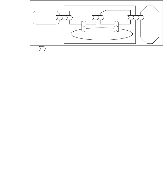
Ports
M
2
m
1
m
3
s
1
s
3
s
2
Other polygons: different model types
FIGURE 14.10 MXL multimodel structure.
<?xml version="1.0" encoding="utf-8"?>
<MXL>
<fbm id="MXL">
<block id="F1">
<output id ="F1_outports_integer1"datatype="Integer" index="0"/>
<script lang="Python" src="input.py" func="gen"/>
</block>
<block id="F2">
<input id="F2_inports_integer1" datatype="Integer" index="0"/>
<output id="F2_outports_string1" datatype="String" index="0"/>
<fsm id="FSM_F2" src="FSM_F2.xml"/>
</block>
<trace from="F1_outports_integer1" to="F2_inports_integer1"/>
</fbm>
<simulation start_time="0" end_time="10" delta_time="0.1" cycle_time="0.1"/>
</MXL>
FIGURE 14.11 Functional block model in MXL.
14.3.2 Multimodeling in MXL
Suppose a system could be represented as multimodeling concepts. The system has an FBM with two
blocks (i.e., functions) and one trace; the second block contains an FSM with two states and two transitions
(i.e., interlevel coupling). Figure 14.11 and Figure 14.12 show the MXL representation for the system.
In Figure 14.11, the MXL contains fbm and simulation as subelements. fbm represents model type
(i.e., FBM) and has two elements, block and trace. Each block element has an attribute, id, to specify the
names of blocks. In addition, the element has port information, input or output as well as its function-
ality, script.Eachinput and output element contains id, datatype, and index, which define the name of
input/output, data type of input/output, and the number of input/output, respectively. The script element
has lang, src, and func to specify program language, the name of the script file, and function to be exe-
cuted, respectively. If a block contains another model type (i.e., multimodel), the model type and its MXL
can be specified in the block (i.e., Block F2 in Figure 14.11.) trace has from and to attributes denoting
connectivity between blocks. Simulation has specific information for executing a certain dynamic model
such as start time, end time, and delta time. Figure 14.12 depicts an internal dynamic model type which
Block F2 contains. In this case, the MXL represents the FSM. Therefore, MXL has state and transition as
subelements. Likewise, each state and transition has its id, script information, and topological connectivity.

Multimodeling 14-13
<?xml version="1.0" encoding="utf-8"?>
<MXL>
<fsm id="FSM_F2">
<input id="F2_inports_integer1" datatype="Integer" index="0"/>
<output id="F2_outports_string1" datatype="String" index="0"/>
<state id="S1" start="true">
<script lang="Python" src="input.py" func="off"/>
</state>
<state id="S2">
<Script lang="Python"src="input.py" func="on"/>
</state>
<transition from="S1" to="S2">
<script lang="Python" src="input.py" func="off2on"/>
</transition>
</transition from="S2" to="S1">
<script lang="Python" src="input.py" func="on2off"/>
</fsm>
</MXL>
FIGURE 14.12 Finite state model in MXL.
Using an MXL-to-DXL translator, the MXL file can be translated into DXL, which is a homogeneous
assembly level block diagram modeling language consisting of Connectors, Blocks, and Ports. The concepts
of DXL will be explained semantically and syntactically in the next section.
14.4 Dynamic Exchange Language (DXL)
14.4.1 DXL Concepts
DXL is a unified, low-level functional specification language, and associated diagrammatic presentation
for simulation on the RUBE framework. In simple DXL models, models are defined by connection of
input and output ports of primitive models such as multipliers or adders.
In DXL multimodels, the models may be abstracted upper-layer block models in the form of sublayer
models. DXL combines the lower-level block models of subsystems to describe a complex system hierarchi-
cally (i.e., homogeneous multimodeling). Because each DXL model has its outermost block as a wrapper,
it supports the important characteristics for multimodeling, composability, and reusability.
When each block plays a role as a leaf node in the structure of a multimodel, it can be encoded in one
of the programming languages, such as JavaScript or Python. Multiple programming languages become
the target codes for DXL-to-simulation translators, and an actual data flow for simulation is achieved by
using XML data and schema.
In this section, a diagrammatic presentation and formalism for DXL, which operates like a circuit, is
created. Ports constitute the interface that defines the boundary of components or subsystems in a system
configuration. MXL and DXL ports are used for port coupling where all ports match in number and data
type. MXL ports are used for conceptual multimodeling in the RUBE framework. DXL ports, however, are
utilized to support the multimodel execution as well as to maintain the conceptual multimodeling. A DXL
or MXL model supports not only streaming of simple data types but also XML “information streaming”
since DXL ports are capable of encoding documents (i.e., XML documents) rather than data under the
XML-based environment. XML schemata that define the typing structure accompany the “types.”
14-14 Handbook of Dynamic System Modeling
14.4.2 Syntax of DXL
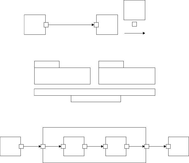
The right side of Figure 14.13 shows syntax elements of DXL. DXL elements are composed of blocks, input
and output ports, and connects. Generally, a DXL model is composed of “block” and “connect” elements.
A DXL block element is composed of “port” elements and “its actual computation codes.” DXL block
elements are connected by each connect element through input and output port elements, which can be
included in a block element. Each port element is connected to the corresponding output and input port
elements of other block elements for its data flow, which each connect element controls.
The left side of Figure 14.13 shows a simple DXL model consisting of two blocks and one connect. This
model shows that the output becomes the input of “Block 2” after the computation of “Block 1”is finished.
Therefore,“Block 2” executes its own computation using the output of “Block 1” as its input.
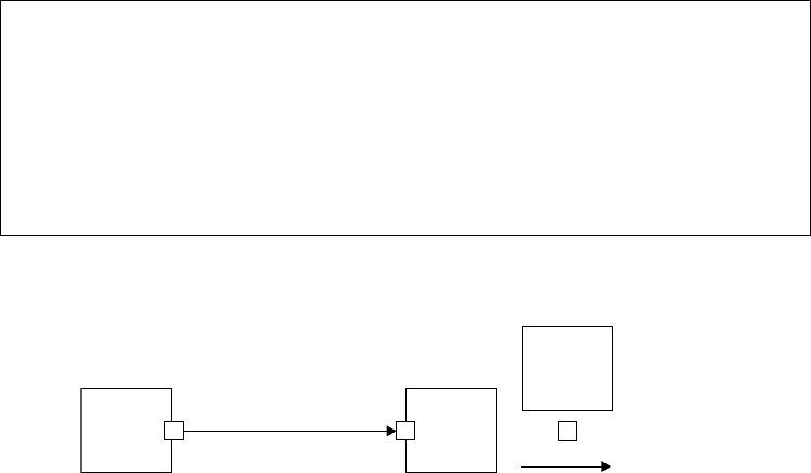
Each block becomes an object in object-oriented programming unlike a function in procedure program-
ming. Input and output ports become the variables that are defined in the block objects according to their
data types such as primitive and object data types. From the viewpoint of object-oriented programming,
therefore, the DXL model of Figure 14.13 is explained in Figure 14.14.
The DXL block element might include another DXL model when it represents a homogeneous multi-
model. In Figure 14.15,“Outer Block B” does not have “its actual computation codes,” but it does contain
another DXL model. Therefore, when “Outer Block B” starts, the input of “Outer Block B” becomes the
input of “Inner Block a.” In contrast, when “Outer Block B”finishes, the output of “Inner Block b”becomes
the output of “Outer Block B.”According to the flow of “connect”elements, after the inner blocks of “Outer
Block B” are executed, the output of “Outer Block B” becomes the input of “Block C” in Figure 14.15.
Input
port
Output
port
Port
Block
Connect
Block 1 Block 2
FIGURE 14.13 DXL syntax.
Object B1
Input ports variables
Output ports variables
Methods
Object B2
Input ports variables
Output ports variables
Methods
When the output of B1 is sent to the input of B2
B2.input = B1.output
FIGURE 14.14 DXL programming semantics.
A. OP
Inner Block a
Block A
Inner Block b
Outer Block B
B. IP B. OPa. IP b. IP
a. OP b. OP
Block C
C. IP
FIGURE 14.15 DXL multimodel syntax.
Multimodeling 14-15
14.4.3 Semantics of DXL
14.4.3.1 Notation
Figure 14.16 defines a notation to describe the functionalities of DXL blocks. We describe algorithmic
semantics of blocks using a set theory and some pseudocodes. IP and OP mean input port and output
port of a block. For notation of DXL ports, the orders of the ports are expressed as an argument of IP or
OP, and the identifiers of their parent blocks are subscripted. Therefore, the first and second input ports
ofblockB1becomeIP
B1
(1) and IP
B1
(2). The first and second output ports of block B1 become OP
B1
(1)
and OP
B1
(2). OB means output blocks of current block. The input ports of these output blocks receive
the output after the current block finishes its computation. For notation of DXL output blocks, the orders
of output ports of the current block are presented as arguments of OB, and the identifier of the current
block is subscripted. Therefore, the output blocks of the first and second output ports of the current block
B1 become OB
B1
(1) and OB
B1
(2).
14.4.3.2 Information Stream Mechanism
Generally, a DXL model is composed of “block”and“connect”elements. A DXL block element is composed
of“port”and“definition”elements. It mightinclude another DXL model when it represents a homogeneous
multimodel. The DXL block elements are connected by each connect element through the input and
output port elements, which are included in a block element. The data flow between block elements is
notated by the pseudocode SEND, which means different information streaming according to the various
environment modes. For example, the pseudocode SEND means “generate next event” based on discrete-
event scheduling methods (Fishwick, 1995) in sequential simulation, and also “send message” based on
message-passing protocols in distributed simulation. This information streaming abstraction approach,
which is used to generate different target codes on heterogeneous environments, makes it easy to create a
DXL-to-simulation translator and integrate model components.
In Figure 14.17, the meaning of the SEND pseudocode is “transfer DATA in an output port OP of a block
B1 to an input port IP of a block B2 and generate next event B2, after time t passes,”based on discrete-event
scheduling methods. If this model is based on message-passing protocols in distributed simulation, this
Notation
IP
i
: a set of input ports for a block i
IP
i
(n): the nth input port of a block i
OP
i
: a set of output ports for a block i
OP
i
(n): the nth output port of a block i
OB
i
(j): a set of output blocks for the jth port of a block i
SEND(t, DATA(i), IP
k
(j)): Current block sends data of ith output
port to jth input port of block k after time t
FIGURE 14.16 DXL block notation.
IP
2
(1)OP
1
(1)
SEND (t
1
, DATA(1), IP
2
(1))
Input port
Block
Connect
Block 1 Block 2
FIGURE 14.17 Augmented DXL syntax.

14-16 Handbook of Dynamic System Modeling
IP
i
(1)
IP
i
(m) OP
i
(n)
IP
1
(1)
IP
n
(1)
OP
1
(1)
OP
M
(1)
SEND (t
1
, DATA(1), IP
i
(1)) SEND (t
i
, DATA(1), IP
1
(1))
SEND (t
m
, DATA(1), IP
i
(m)) SEND (t
i
, DATA(1), IP
n
(1))
Block 1
Block m
Block 1
Block n
Block i
OP
i
(1)
FIGURE 14.18 Examples of SEND pseudocode.
SEND pseudocode means “create DATA in an output port OP of a block B1 as a message and send the
message to an input port IP of a block B2, after time t passes.”
In Figure 14.18, the meanings based on discrete-event scheduling methods of SEND pseudocodes are
as follows:
•
SEND (t
1
, DATA(1), IP
i
(1)): transfer DATA in an output port OP of a block B
1
to an
input port IP1 of a block B
i
and generate next event B
i
, after time t
1
passes.
•
SEND (t
m
, DATA(1), IP
i
(m)): transfer DATA in an output port OP of a block B
M
to an
input port IPm of a block B
i
and generate next event B
i
, after time t
m
passes.
•
SEND (t
i
, DATA(1), IP
1
(1)): transfer DATA in an output port OP1 of a block B
i
to an
input port IP of a block B
1
and generate next event B
1
, after time t
i
passes.
•
SEND (t
i
, DATA(1), IP
n
(1)): transfer DATA in an output port OPn of a block B
i
to an
input port IP of a block B
N
and generate next event B
n
, after time t
i
passes.
In Figure 14.18, the meanings based on message-passing protocols in distributed simulation of SEND
pseudocodes are as follows:
•
SEND (t
1
, DATA(1), IP
i
(1)): create DATA in an output port OP
1
of a block B
1
as a
message and send the message to an input port IP
1
of a block B
i
, after time t
1
passes.
•
SEND (t
m
, DATA(1), IP
i
(m)): create DATA in an output port OP
1
of a block B
m
as a
message and send the message to an input port IP
m
of a block B
i
, after time t
m
passes.
•
SEND (t
i
, DATA(1), IP
1
(1)): create DATA in an output port OP
1
of a block B
i
as a
message and send the message to an input port IP
1
of a block B
1
, after time t
i
passes.
•
SEND (t
i
, DATA(1), IP
n
(1)): create DATA in an output port OP
n
of a block B
i
as a
message and send the message to an input port IP
1
of a block B
n
, after time t
i
passes.
14.4.3.3 Synchronous Input Property
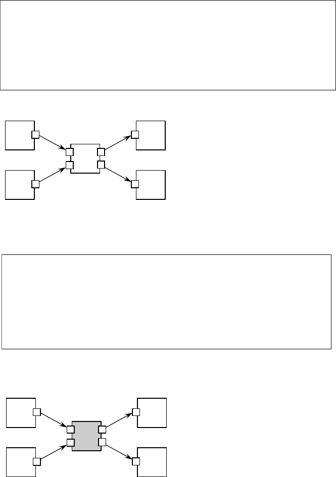
Block B3 in Figure 14.19 divides the output of block B1 with the output of block B2 and then sends its
quotient to block B4 and remainder to block B5. To make the division, block B3 should have two inputs at
the same time (i.e., a synchronous block in DXL). Note that the block has two output ports to support a
different output at the same time unlike the functions of traditional programming languages, which have
only one output. The right side of Figure 14.19 describes the processing algorithm of block B3.
14.4.3.4 Asynchronous Input Property
In Figure 14.20, block B3 plays a role in switching input data. It is not necessary to receive both inputs to
relay its data. In other words, the block just relays its input to its next block whenever it receives the input.
The block should therefore have an asynchronous input property, which is depicted with a gray color. The
switch block algorithm is described on the right side of Figure 14.20. In DXL, the above combinations of
simple blocks and their properties create an actual model for a system.
Multimodeling 14-17
Algorithm for a block having synchronous inputs
if(for ∀x∈IP
i
, x has input data) then
The computation of the function in a DXL block
For ∀y
∈P
i
, if(y has output data) then for z∈OB
i
(y), SEND(t,
DATA(y), z) elseif
IP1
IP2
OP1
OP2
Algorithm for block B3
if (for ∀x
∈IP
B3
, x has input data)
then
OP
B3
(1) ← IP
B3
(1)/IP
B3
(2)
OP
B3
(2) ← IP
B3
(1)%IP
B3
(2)
SEND(t
B4
, DATA(OP
B3
(1)), B4)
SEND(t
B5
, DATA(OP
B3
(2)), B5)
elseif
B1
B2
B4
B5
B3
(ⴜ)
FIGURE 14.19 Example of synchronous inputs.
Algorithm for a block having asynchronous inputs
if(for ∃x
∈IPi, x has input data) then
The computation of the function in a DXL block
For ∃y
∈OP
i
, if(y has output data) then for z∈OB
i
(y),SEND(t,
DATA(y), z) elseif
Algorithm for block B3
if (IP
B3
(1) has input data) then
OP
B3
(2) ← IP
B3
(1)
SEND(t
B5
, DATA(OP
B3
(2)), B5)
elseif
if (IP
B3
(2) has input data) then
OP
B3
(1) ← IP
B3
(2)
SEND(t
B4
, DATA(OP
B3
(1)), B4)
elseif
IP1
IP2
OP1
OP2
B1
B2
B4
B5
B3
switch
FIGURE 14.20 Example of asynchronous inputs.
14.4.4 Multimodeling
ForDXL,multimodeling is defined by specifyinga block circuit inside of a block, and continuingrecursively
as needed. Ports are coupled by ensuring matching data types for each connecting port on each connector.
The general DXL methodology in transforming heterogeneous models (MXL models) into homogeneous
models (DXL models) is as follows:
•
Transform submodels in an MXL multimodel into DXL models and
•
Incorporate each of the transformed models according to port coupling.

14-18 Handbook of Dynamic System Modeling
Translation
K
x
x x
a
兰兰
K
兰兰
FIGURE 14.21 Translation of an FBM into a DXL model.
14.4.4.1 FBM-to-DXL Translation
The FBM is composed of functional elements where functions, along with inputs and outputs, are often
depicted in a “block” form. An arbitrary number of blocks can be coupled to form an FBM. This FBM is
similar to DXL except for synchronous and asynchronous inputs of DXL. Therefore, functions of FBM
are translated into DXL blocks, and FBM’s inputs and outputs are translated into DXL input and output
ports. Because each block of traditional FBM has a pure function, all inputs of the function should be
valid before the block is executed, meaning all FBM blocks have synchronous property for inputs.
An FBM for the differential equation x
=−ax
is described on the left side of Figure 14.21. This
FBM is composed of four blocks: two integrators, one multiplier, and one constant. Because each block
of a traditional FBM has a synchronous input property, these blocks are translated into blocks having
synchronous inputs in DXL. Its arrows are translated into connectors of DXL. This FBM also has a
continuous simulation property. To support the property, a start block of the DXL model is generated
every simulation unit time.
14.4.4.2 FSM-to-DXL Translation
The FSM has states and transitions. A state represents the current condition or “snapshot” of a system
for some length of time. Transitions enable the system to move from one state to another during the
simulation while under the control of the system input. The basic rule of translating FSM into DXL is that
all functional elements are translated into DXL blocks. The transitions of FSM are predicates under the
system input and can, therefore, be translated into DXL blocks. These DXL blocks have the same type of
input ports as the system input and a Boolean type of output ports that decide whether the predicates are
true or false. Since states have the functional properties to access the system input, all states are translated
into DXL blocks. In addition, we need the special block to control the system input.
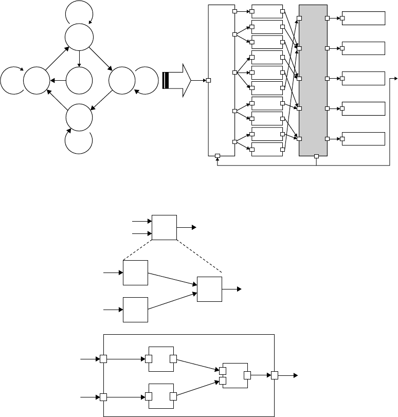
The left side of Figure 14.22 shows an FSM modeling of a four-stroke gasoline engine with four phases:
compression, ignition, expansion, and exhaustion. The key point that makes FSM different from FBM is a
state-based model. To translate a state-based model into a function-based model, all states and transitions
are translated into DXL blocks. Then DXL connectors and block properties control the semantics of
the state-based model. The right side of Figure 14.22 shows a translated DXL model for the four-stroke
gasoline engine. If we made a DXL code manually, we could create a simpler DXL code than the right side
of Figure 14.22. But to make automatic MXL-to-DXL translation easy, we used the DXL model to include
INPUT and OUTPUT blocks, as in Figure 14.22. Our translator generated the INPUT and OUTPUT
blocks to control the FSM semantics. The right blocks next to INPUT blocks are translated transition
blocks and the right blocks next to OUTPUT blocks are translated state blocks.
14.4.4.3 Multimodeling between Homogeneous Models
In Figure 14.23, the upper model is a two-level functional hierarchy, where function f is defined in terms
of a composition of three other functions f
1
, f
2
, and f
3
. The lower model shows multimodeling in DXL
for the upper model. Because DXL is specifically based on a functional block diagram, FBM models in
Figure 14.23 are refined only if the number and types of ports are matched.
Multimodeling 14-19
0
11
Ignition
Ignition
Input
data
INPUT
OUTPUT
Off
O_C
C_C
C_I
I_I
I_E
I_O
E_E
E_Ex
Ex_Ex
Ex_C
Off
Expan-
sion
Expansion
Exhaus-
tion
Exhaustion
Compres-
sion
Compression
2
1
11
0
0
0
FIGURE 14.22 Translation of an FSM into a DXL model.
f
f
3
f
1
f
2
i
1
i
2
o
o
o f(i
1
, i
2
)
o f
3
(f
1
(i
1
), f
2
( i
2
))
f
f
3
f
1
i
2
i
1
f
2
i
1
i
2
i
1
i
2
oo
o f(i
1
, i
2
)
o f
3
(f
1
(i
1
), f
2
(i
2
))
FIGURE 14.23 Multimodeling between functional block models in DXL.
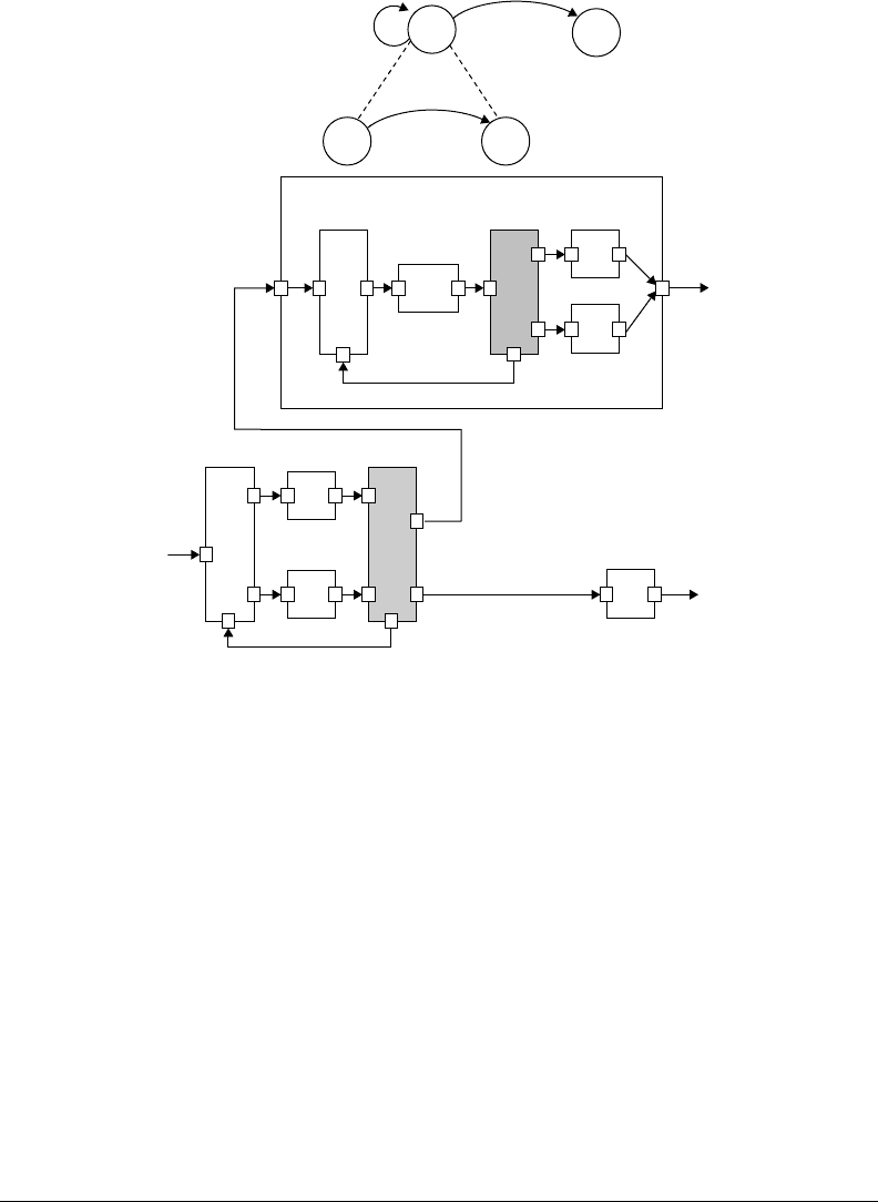
In Figure 14.24, the upper model is a two-level finite state hierarchy, where state s
1
is defined in terms of
another FSM. The lower model shows the transformed DXL model for the two-level finite state hierarchy.
All FSMs should have this kind of functional box around them to represent external input and output
semantics even though the functional box is not expressed explicitly in the FSM graphical representation.
Because FSMs represent behavior or dynamics of another component in multimodeling, an FSM is
inserted in it to represent a state more specifically. In that case, multimodeling between FSMs should be
supported, but there is a difficulty in integrating the two FSMs because of the implicit expression of input
and output in FSMs.
However, in DXL, states and transitions in FSMs are transformed into the same blocks. MXL-to-DXL
translator generates special blocks, which control state and transition blocks (i.e., INPUT and OUTPUT
blocks). In Figure 14.24, after a submodel (i.e., the lower FSM model) is transformed into a DXL model, it
is inserted in its upper state block and then connected with external input and output ports using connect
elements in DXL.
14-20 Handbook of Dynamic System Modeling
s
1
s
2
s
11
s
12
p
2
(i )
p
11
(i )
p
1
(i )
s
2
p
1
(i )
i
i
I
N
P
U
T
O
U
T
P
U
T
s
1
p
2
(i )
o
s
12
s
11
p
11
(i )
i
I
N
P
U
T
O
U
T
P
U
T
o
FIGURE 14.24 Multimodeling between FSM models in DXL.
14.4.4.4 Multimodeling between Heterogeneous Models in DXL
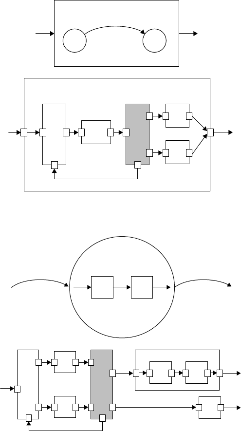
In Figure 14.25, the upper model is the same model as shown in Figure 14.4. The submodel in this figure
is an FSM that defines the internal state transitions associated with function f . The generated DXL model
for an FSM is inserted in function f . Because the number and types of input and output of the function
f are the same as the input and output ports of the DXL model, the integration is accomplished through
port matching.
In Figure 14.26, a state of an FSM decomposes into an FBM to represent internal functionality. The
state in an FSM is different from an FBM from the viewpoint of a system. In an FSM, while input and
output are not specified explicitly, control flow is unclear in an FBM. In a DXL model, however, the input
and output of transformed FSM states are specified explicitly, which makes it easier for the integration of
the components of an FSM and the components of an FBM. The lower model in Figure 14.26 indicates
a transformed DXL multimodel. A sublayer of the model, a transformed DXL model for an FBM, is
connected to the input and output ports of the outer state block s
1
.
14.5 A Boiling Water Example
In this section, we explain how multimodeling environments (i.e., integrative and general multimodeling
environments) can be implemented in the Blender 3D environment through our methodology, as proposed
in the previous sections, using the example of the boiling water scene. The pot is filled to a predetermined
level with water. A small amount of detergent is added to simulate the foaming activity that occurs
Multimodeling 14-21
s
1
s
2
p(i )
i
i
o
f
f
o
s
1
s
2
p(i )
I
N
P
U
T
O
U
T
P
U
T
FIGURE 14.25 Multimodeling for an FBM including an FSM in DXL.
f
1
f
2
i
o
p
1
(i )
p
2
(i )
s
1
f
2
s
2
p
1
(i )
i
o
O
U
T
P
U
T
f
1
s
1
p
2
(i )
i
I
N
P
U
T
o
FIGURE 14.26 Multimodeling for an FSM including an FBM in DXL.
naturally when boiling certain foods. This system has a temperature knob. The knob is considered to be in
one of two states: on or off. We first define the following conditions and assumptions in connection with
this scene:
•
External event: I ={ON, OFF}
•
Internal event: T ={T =α, α<T < 100, T =100}
•
Input space: {(I =ON, T =α), (I =ON, α<T < 100), (I =ON, T =100), (I =OFF, T =α),
(I =OFF, α<T < 100), (I =OFF, T =100)}
•
Boiling state: T =100
•
Heating state: T
=k
1
(100 −T)
•
Cooling state: T
=k
2
(α −T).
