Fishwick P.A. (editor) Handbook of Dynamic System Modeling
Подождите немного. Документ загружается.

15-4 Handbook of Dynamic System Modeling
Window controllerTop controllerLights controller
dc motor
Window mechanism
Current
sensor
Periodic
Aperiodic
Continuous
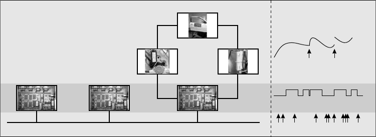
FIGURE 15.3 A hybrid dynamic system with different behavior classes.
automobile and connects the ECU that interfaces with the window up and down button to the ECU that
interfaces with the window lift mechanism. Network traffic is often modeled as aperiodic events.
The design of such a system typically proceeds by determining a set of requirements that it has to satisfy.
Among these requirements it may state that (Friedman and Ghidella, 2006)
1. The window should be closed within 5 s.
2. The passenger command should always be overruled by the driver command.
3. The driver and passenger commands should be acted upon within 200 ms.
To validate Requirement 1, a continuous-time model of the lift mechanism is best used. This could be
a set of differential and algebraic equations (DAEs) that model how fast the window with mass, m
window
,
moves, v
window
, given a voltage on the dc motor, u
motor
, and the corresponding current that the motor
draws, i
motor
. The equations
F
motor
= ru
motor
F
window
= m
window
˙v
window
F
lift
= R
lift
v
window
i
motor
= rv
window
F
window
+F
lift
= F
motor
˙x
window
= v
window
(15.1)
model the conversion of the dc motor voltage by a parameter, r, and include linear friction, R
lift
, that
causes a friction force component, F
lift
, for the lift mechanism. Solving this system of equations over time
shows whether the window can rise quickly enough for certain input voltages by evaluating the window
position, x
window
.
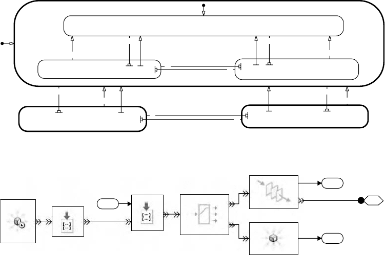
In contrast, the control structure that Requirement 2 addresses is best modeled by a state machine that
has hierarchical structure of its states. This allows the passenger commands to execute when the driver
commands are neutral. When the driver issues a command, the passenger control structure is departed
and overruled by the driver command. This is illustrated by the Stateflow
®
(Stateflow, 2004) chart in
Figure 15.4.
In this Stateflow chart, there are three states for the driver control, driverNeutral, driverDown, and
driverUp. When driverDown is the active state, the window is moved down, and when the driverUp state
is active, the window is moved up. The driverNeutral state is of a hierarchical nature, and contains the
control structure for the passenger, analogous to the control structure for the driver. In this manner, the
driver control takes precedence over the passenger control, and the passenger may command the window
only if the driver does not issue a command (i.e., a neutral command). The initial states are indicated by
Hybrid Dynamic Systems: Modeling and Execution 15-5
[drvDown]
2
[endstop]
1
[drvNeutral] [drvNeutral] [drvUp]
1
[endstop]
1
[drvUp]
2
[drvDown]
2
driverNeutral
[endstop]
1
[pasDown] [pasNeutral] [pasNeutral] [pasUp]
1
[endstop]
1
[pasUp]
2
[pasDown]
2
passengerNeutral
passengerUp
passengerDown
driverUp
driverDown
2
FIGURE 15.4 A finite state machine in the form of a Stateflow chart.
2
Arrived entities
1
Average wait
1
Packet
IN
OUT1
OUT2
Transmit or drop
IN
A1
OUT
Set value
attribute
IN OUT
Set destination
attribute
OUT
Packet
generator
IN
OUT
w
FIFO queue
IN #a
Dropped packet
1
Command
FIGURE 15.5 An entity network model of a transmitter.
a transition that is depicted by an arrow with a solid circle on one end and arrow head on the other end.
Note that the ordering of transitions that could be activated simultaneously is indicated by the numbers
associated with the respective transitions.
The events issued by the driver, drvUp and drvDown, command the window to go up or down. When
any of the commands is released, the drvNeutral command is issued. The behavior is similar with the
passenger-related commands pasUp, pasDown, and pasNeutral.Theendstop command is issued when the
window has reached the top or bottom of the door frame.
To validate the response time as put forward in Requirement 3, the communication network needs
to be modeled. In this case, a server/queue type model is best used where the network is modeled as a
server that aperiodically frees up and passes a packet from one ECU to another. A SimEvents
™
(SimEvents,
2005) model of the packet transmitter is shown in Figure 15.5. Here, the command as issued by the driver
is assigned as the attribute of packets that are generated at a fixed rate. The packets themselves have an
attribute that identifies their destination. The system then attempts to put the packets into a first-in-first-
out (FIFO) queue and if this fails, they are lost as dropped packets. The FIFO queue is connected to another
subsystem, which models the CAN bus behavior.
Stochasticserver times may be included to model the variable arrival times of network requests from con-
trol systems (such as the headlights control system) that communicate using the same CAN. This is a type
of system integration test that is often performed in hardware because the different systems are provided by
different suppliers, and the models used for the design of each system are not shared among these suppliers.
Combining all these different types of models that are needed to verify the requirements necessitates
handling both continuous-time differential equation models as well as discrete-event state-transition
models. This can be achieved, for example, by transforming the continuous-time models into discrete-
event representations or the other way around. Alternatively, a computational model can be designed that
can handle both the continuous-time and discrete-event behavior. This latter approach leads to the hybrid
dynamic execution structure.
15-6 Handbook of Dynamic System Modeling
15.2.2 What Is a Hybrid Dynamic System?
A hybrid dynamic system is defined in behavioral terms, because it is model structure agnostic, and,
therefore, does not impose unnecessary and undesired modeling assumptions.
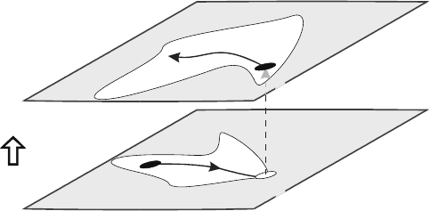
In a geometric sense, a hybrid dynamic system evolves continuously in time in a mode, α
i
, according to
a field, f
α
i
(Guckenheimer and Johnson, 1995; Mosterman and Biswas, 1997). This field defines a relation
f
α
i
(˙x, x, u, t) =0 between the state, x, its time derivative, ˙x, the input u, and the time, t. This is illustrated
in Figure 15.6, where the continuous-time behavior is shown as a solid directed line in the plane α
1
.
The continuous-time behavior is often captured by an explicit representation as a set of differential
equations
˙x = f
α
i
(x, u, t) (15.2)
where α
i
is the mode of the model, x the continuous-time state vector, u the exogeneous input, and t the
time. An alternative formulation is the implicit form
f
α
i
(˙x, x, u, t) = 0 (15.3)
often used in plant modeling, and the semi-explicit form that has an explicit representation of the time
derivatives, f
d
α
i
, combined with a set of implicitly formulated algebraic constraints (van Dijk, 1994), f
a
α
i
,
˙x = f
d
α
i
(x, u, t), 0 = f
a
α
i
(x, u, t) (15.4)
In Figure 15.6, the change to mode α
2
occurs when the state in mode α
1
, x
α
1
, reaches a threshold value.
In general, a mode transition relation γ
α
i+1
α
i
(x, u, t) ≥0 defines the change from mode α
i
to α
i+1
when true.
The state space in a mode α
i
consists of two parts: (i) the domain where f
α
i
is properly defined and (ii)
a patch,whereγ
α
i+1
α
i
does not invoke a mode change. In Figure 15.6, the patches are shown as white areas
in the state space. When the boundary of the patch in α
1
is reached, a mode transition as defined by γ
α
2
α
1
is invoked. In the new mode, a patch defined by γ
α
3
α
2
is entered in which the state can continue to evolve,
now governed by the field f
α
2
.
When a mode transition from α
i
to α
i+1
takes place, in general, the state x
α
i
may change its value
to x
α
i+1
. Without loss of generality it is first assumed that the explicitly defined state transition func-
tion, x
α
i+1
=g
α
i+1
α
i
(x
α
i
, u
α
i
, t), is the identity function, i.e., x
α
i+1
=x
α
i
, as shown in Figure 15.6 by the
perpendicular dashed arrow.
1
2
g
1
2
f
1
2
1
f
2
x
2
x
1
FIGURE 15.6 Geometric representation of a hybrid dynamic system. (From Mosterman, P. J. Mode transition
behavior in hybrid dynamic systems. In Proceedings of the 2003 Winter Simulation Conference, pp. 623–631, New
Orleans, LA, December 2003 (invited paper).)
Hybrid Dynamic Systems: Modeling and Execution 15-7
15.2.3 How Are Hybrid Dynamic System Models Designed?
The behavioral definition of hybrid dynamic systems left open the specific underlying model structure
that is employed. There are two basic approaches to the design of hybrid dynamic system models: (i) an
implicit approach and (ii) an explicit approach.
15.2.3.1 Implicit Models
In modeling for analysis, often an implicit approach is favored. This is best illustrated by considering the
modeling of a physical device under control, the plant, such as the power window mechanism of the system
in Figure 15.3. The continuous-time behavior that models moving the window up is given in Eq. (15.1)
in an implicit form. The equations are not converted in an explicit form that allows their solution yet.
For example, the velocity of the window, v
window
, is a state variable and so its time derivative needs to be
computed by the system of equations in Eq. (15.1). However, applying Newton’s Second Law of Motion
leads to a formulation with the force, F
window
, on the left-hand side. To arrive at an explicit computation
of ˙v
window
, the equation has to be reformulated into
˙v
window
=
F
window
m
window
(15.5)
The reason for the implicit formulation is modeling convenience. It is often easier to model physical
constraints in an implicit, constraint-based form such as Newton’s Second Law of Motion. Another such
constraint is, for example, conservation of momentum,
m
i
v
+
i
=
m
i
v
−
i
(15.6)
which states that the some of the momentum, m
i
v
−
i
, of each body, m
i
, with velocity, v
−
i
, before a collision
and after a collision, m
i
v
+
i
, should be the same. Which velocities are input to this constraint, and which
ones are computed from the constraint, is left implicit.
In the same vein, mode changes in models of physical systems are often best represented in an implicit
manner. For example, when the window reaches the top of its frame,further upward movement is restricted
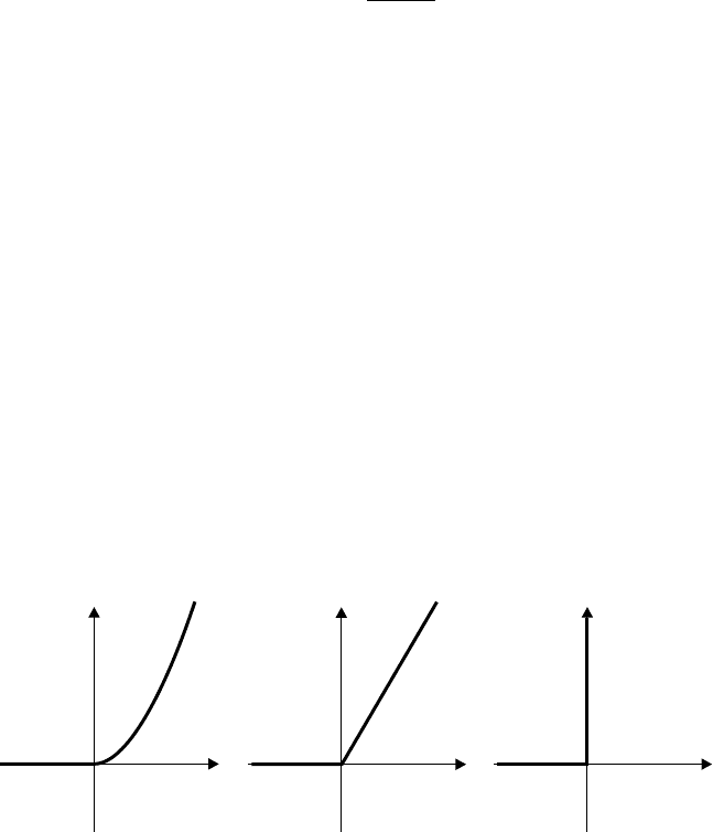
by a rapid increase of resistance to motion. This can be modeled in three different manners, illustrated in
Figure 15.7.
•
By a nonlinear resistance that is distance-dependent and rapidly increases when the window reaches
the top of the frame position (Figure 15.7[a]).
•
By a piecewise linear resistance that abruptly changes the resistance value when the window reaches
the top of the frame position (Figure 15.7[b]).
•
By an ideal switch of the resistance that enforces a hard stop when the window reaches the top of
the frame position (Figure 15.7[c]).
F
v
0
(a)
0
(b)
F
v
0
(c)
F
v
FIGURE 15.7 Abstraction classes for endstop models. (a) Nonlinear, (b) C
0
hybrid, and (c) ideal switch.
15-8 Handbook of Dynamic System Modeling
These three classes of modeling approaches are typical in the modeling of physical systems with perceived
discontinuities. The latter two lead to hybrid dynamic systems.
To illustrate how the window reaching the top of the frame could be formulated as a mathematical
relation that represents an ideal switch, the equation F
window
+F
lift
=F
motor
in Eq. (15.1) is replaced by
0 = L(F
window
+F
lift
−F
motor
) +(L −1)v
window
(15.7)
where L is a logical variable that switches based on the window position, x
window
,whereL =x
window
≤x
top
.
Such “local” and “implicit” switching of equations is intuitive and convenient in the domain of plant
modeling.
15.2.3.2 Explicit Models
Controller modeling typically takes a different perspective because the modeled behavior is the explicit
objective of the design. As such, implicit modeling constructs such as algebraic loops that have
a cyclic dependency (e.g., x =−2x +3) are not desired or even illegal (such as for real-time code
generation).
The corresponding continuous-time formalism that is often used in control system design is explicit
ordinary differential equations (ODEs). Whereas the DAEs used for implicit modeling are of the form
0 =f (˙x, x, u, t), the explicit ODE form is ˙x =f (x, u, t). This form is especially popular because it is
amenable to control law synthesis, in particular when it is linear. For example, when the behavior of the
lift mechanism of the power window in Figure 15.3 is available in an explicit linear ODE form, root-locus
methods can be applied to design a controller that can achieve the desired behavior, such as the position
overshoot in response to a step input (Control System Toolbox, 2004).
The discrete-event behavior is often modeled by finite state machines. For example, state transition
diagrams are graphical models that represent finite state machines. The different modes of behavior then
correspond to the states of the transition diagram, and, consequently, are explicitly available. In addition,
the imperative nature of state transition diagrams makes the state transition behavior become operational.
The modeler has rendered the manner in which the transitions between states are made explicit. In the
implicit formulation, constraints are provided on the modes, and a transformation to an operational form
has to still be derived.
The combination of state transition diagrams and ODEs has been a popular modeling approach for
control design as its explicit nature makes it amenable to reachability analyses (e.g., Lynch and Krogh,
2000). Such hybrid automata (Alur et al., 1993) consist of discrete states with associated ODEs. When in a
state, the associated ODE governs continuous-time behavior. The transitions between states are enabled by
guards and when enabled, the transition from one state to another may be taken. Each state has an invariant
associated with it as well that cannot be violated while in that state. When the continuous behavior in a
state reaches a point where it would violate the corresponding invariant, an enabled transition must be
available and taken.
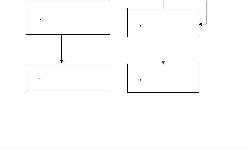
To illustrate, Figure 15.8(a) shows a hybrid automaton for the power window behavior that is modeled
in an implicit form in the previous section. The state (also called mode as it captures the mode of operation
of the entire system) on the left-hand side models the window moving up by the two equations for v
window
and ˙x
window
. The invariant of the state is x
window
< x
top
, which requires that the window can move up
freely; that is, it is not pushing against the top of the frame.
When the top of the frame is reached, x
window
≥x
top
becomes true and the transition into the right-hand
state is enabled. Because the invariant x
window
< x
top
becomes false at the same time, the transition is forced
to be taken, and the system moves into a state where the window does not move anymore (v
window
=0).
In case some bounce-back effect would be modeled because of the window colliding with the top of
the frame, the continuous-time state v
window
could be reinitialized with a value −ηv
window
,whereη is
a coefficient of restitution. This reinitialization can be included on the enabled transition as an action
v
window
=−ηv
−
window
, as shown in Figure 15.8(b). Note that the superscript is to indicate the left-hand
limit value of the continuous-time behavior.
Hybrid Dynamic Systems: Modeling and Execution 15-9
x
window
≥ x
top
inv: x
window
≥ x
top
v
window
0
x
window
v
window
inv: x
window
x
top
v
window
F/m
x
window
v
window
(a)
inv: x
window
x
top
v
window
F/m
x
window
x
top
&
v
window
v
bounce /
x
window
x
top
&
v
window
v
bounce
v
window
– h v
-
window
inv: x
window
x
top
v
window
0
x
window
v
window
x
window
v
window
(b)
FIGURE 15.8 Hybrid automaton of power window endstop behavior. (a) without bounce back and (b) with bounce
back.
15.3 Hybrid Dynamic System Behaviors
The different aspects of generating behaviors for hybrid systems are discussed and efficient methods to do
so are presented.
15.3.1 An Operational Structure
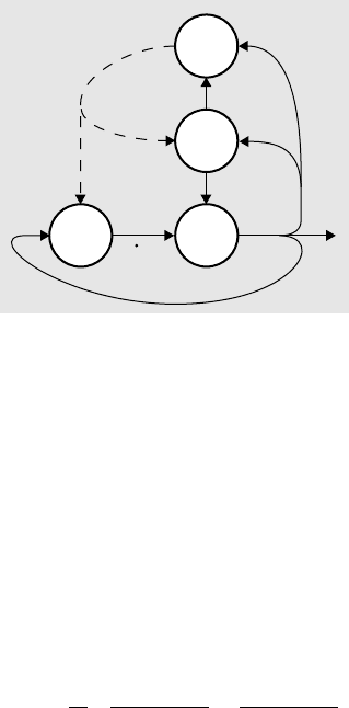
To execute a hybrid dynamic system, three different types of behavior need to be handled (see Figure 15.9)
(Mosterman and Biswas, 2002):
•
Continuous-time behavior as specified by f needstobegenerated.
•
The crossing of thresholds of continuous-timevariables needs to be detected and transitionsbetween
modes of behavior inferred, as specified by γ.
•
The continuous-state variables need to be initialized and possibly reinitialized (think of the window
that bounces back, reversing its velocity), as specified by g.
Each of these parts are reviewed here.
15.3.2 Continuous-Time Behavior
Continuous-time behavior is typically modeled by differential equations, either as ODEs or DAEs. To
generate behaviors, a numerical solver such as differential/algebraic system solver (DASSL) (Petzold, 1982)
can be used to integrate the time-derivative behavior.
Typically, the derivative with respect to time is computed at one or multiple points, after which a
weighted mean is taken to infer the direction of behavior. In its most straightforward form, called a
forward Euler integration scheme, the time derivative, ˙x(t
k
), at a time, t
k
, is multiplied by the step in time,
h =t
k+1
−t
k
, and the resultant is added to the current state, x(t
k
), to produce the state at t
k+1
x(t
k+1
) = h˙x(t
k
) +x(t
k
) (15.8)
15-10 Handbook of Dynamic System Modeling
ff
x
i
+1
x
i
+1
x
i
x
i
i+1
g
g
兰
FIGURE 15.9 Functional model of hybrid dynamic systems.
More sophisticated solvers rely on continuity constraints on the continuous-time behavior. For example,
a second-order Runge–Kutta algorithm is implemented by
m
1
= hf (x(t
k
), t
k
)
m
2
= hf (x(t
k
) +0.5m
1
, t
k
+0.5h) (15.9)
x(t
k+1
) = x(t
k
) +m
2
This scheme is based on a Taylor expansion
x(t
k
+h) = x(t
k
) +hf (t
k
, x(t
k
)) +
h
2
2
∂f (t
k
, x(t
k
))
∂t
+
∂f (t
k
, x(t
k
))
∂x
f (t
k
, x(t
k
))
+O(h
3
) (15.10)
and so it requires the integrated behavior to be continuous up to its third order for the error estimate to be
valid. If this continuity constraint is not satisfied, the integration may still succeed, but without guaranteed
error convergence behavior.
15.3.3 Handling Mode Transitions
Transitioning between two modes of continuous behavior requires: (i) detecting and locating the event
that causes the mode change and (ii) inferring the new mode.
15.3.3.1 Event Detection and Location
The continuous-time behavior of a model typically affects the discrete-event part by events that are
generated by continuous-time variables crossing threshold values. An example of this is when the power
window in Figure 15.2 reaches the top of the door frame.
The exceeding of a threshold can be formulated as an inequality on 0 that either includes the boundary,
γ
α
i+1
α
i
(x, u, t) > 0, or not, γ
α
i+1
α
i
(x, u, t) ≥0. In general, multiple mode transition relations such as both a
relation γ
α
i+1
α
i
(x, u, t) > 0aswellasγ
α
i+2
α
i
(x, u, t) > 0 may apply in any given mode. However, in case of
deterministic models, only one of these should be active. Note that the behavior of the continuous-time
states is best “left-closed”. In other words, each of the abutting intervals of continuous behavior includes
its starting point to satisfy causality requirements (Mosterman, 1999).
An implementation of the event generation requires two parts:
•
First, it has to be detected whether the threshold has been exceeded when an integration step T is
about to be taken.

Hybrid Dynamic Systems: Modeling and Execution 15-11
•
Second, the values of the continuous states, input, and time for which the threshold was first
exceeded have to be determined. In other words, the point in time at which the zero-crossing event
occurs has to be located.
A robust implementation of the event location can be done by means of a bisectional search to find
when the first event (in general there are multiple events) in the T interval occurs. In this case, if an
event is detected, the step size is reduced from T to δt
m
,whereδt
m
is computed based on whether an
event occurs, σ =1, or not, σ =0, in the interval δt
i
as follows
δt
i+1
= δt
i
+t
i
(1 −σ)
t
i+1
=
1
2
t
i
(15.11)
The initial values for this iteration are δt
0
=0 and t
0
=T, and the iteration terminates after a fixed
number of a priori prescribed steps, m.
Other approaches to finding the point in time where the threshold is first exceeded such as regular-falsi
and the illinois algorithm exist (Moler, 1997) and in practical simulation engines a combination of the
different approaches tends to be employed.
Note that this requiresthe model not to change its mode until the zero crossing is located. For example, an
absolute value computation may not be effected while the zero crossing is located. This implies that a nega-
tive value may indeed be computed to ensure that behavior is continuous and, in this case, smooth. In some
cases, such a scheme may not work. For example, in case of a square root computation, a negative value of
the argument is outside of the domain of the square root function (unless complex values are allowed).
15.3.3.2 Mode Transition Inferencing
The discrete events generated by the zero-crossing function may cause a mode change in the model. The
relation γ
α
i+1
α
i
(x, u, t) transitions the model from a mode α
i
toamodeα
i+1
. It takes as arguments the
continuous-time state vector, x, the exogeneous input, u, and time, t. The mode change is typically
implemented as an instantaneous transition, which means there is no passage of time. As such, it is best
modeled by an untimed formalism.
The discrete-state transition behavior can be represented in two basic forms: (i) by combinational logic
and (ii) by sequential logic. This is an important distinction as it makes quite a difference in the complexity
of analyses of the hybrid dynamic systems.
Combinational Logic
An important approach that applies combinational logic is complementarity modeling, which has proven
very successful in the domain of collision modeling (Lötstedt, 1981; Pfeiffer and Glocker, 1996) as well
as, for example, power electronics (Kassakian et al., 1991). Complementarity formulations are further
employed in the work on mixed logical dynamical (MLD) systems (Torrisi and Bemporad, 2004). A linear
complementarity model is of the form
y = Bz + b
yz = 0
y ≥ 0, z ≥ 0
(15.12)
Only one of the variables y and z can be positive while the other has to be 0. This is an intuitive repre-
sentation for points of contact in mechanical systems, where there is either some distance larger than 0
between two bodies and no force acting, or there is no distance and a force larger than 0 acting.
Sequential Logic
In case the logic contains memory, a combinational representation does not apply and sequential logic is
needed. This holds true, for example, for certain models of sequences of collisions such as those found in
Newton’s Cradle (Mosterman, 2007).
Sequential logic can be represented by a state machine, φ, often with a finite number of states (Kohavi,
1978). Many graphical formalisms exist that are of a discrete state, sequential logic, nature. For example,

15-12 Handbook of Dynamic System Modeling
there are state transition diagrams (Kohavi, 1978), statecharts (an example of these are given in Figure 15.4)
(Harel, 1987), and Petri nets (David and Alla, 1992; Murata, 1989). Computationally, a finite state machine
can be represented by a five tuple
φ =α, α
0
, σ, δ, ν (15.13)
in which the state transition function, δ, changes the active state, α, in response to events, σ, while actions,
ν, are generated. The initial state is given by α
0
.
15.3.4 Reinitialization of State Variables
In response to a mode transition inferred by γ
α
i+1
α
i
, the continuous-time state variables may be reinitialized,
as governed by g
α
i+1
α
i
. For example, in case of the power window bounce back, the window reverts its velocity
upon impact with the frame and the corresponding state variable, v
window
, needs to be reinitialized from a
positive to a negative value. An important implication of this is that the numerical solver may have to be
reset. Sophisticated numerical solvers build up a history of time points and based on that history attempt
to take larger steps in time to compute the next integration point. If an integrator state is reset, even if no
mode transition occurs, this history becomes invalid and needs to be cleared. In this case, the integrator
starts off with a minimal step size once continuous-time behavior resumes.
Note that to specify the reinitialization, semantics need to be defined for the two values around a dis-
continuity, the a priori and a posteriori values. In this work, if necessary, the a priori values are indicated
by a “−” superscript, and the a posteriori values by a “+” superscript (see Eq. [15.6], for an example).
Finally, the number of continuous-time state variables may change between mode transitions. For
example, while modeling a highway, vehicles may enter and leave, and, therefore, continuous-time states
would be included or discarded. This, again, will require a reset of the numerical solver, depending on the
integration algorithm that is being used.
15.4 An Implementation
To generate behaviors for a hybrid dynamic system, two basic approaches exist: (i) time-driven execution
and (ii) event-driven execution. The former has the execution driven by moving time forward, often by
means of a numerical solver. The latter jumps in time in response to discrete events.
15.4.1 Classes of Events
For purposes of discussion, it is convenient to first identify two classes of events (Cellier, 1979): (i) time
events and (ii) state events. A time event is an event that occurs at a given point in time, independent of the
continuous-time state of the model, x, and the forcing function, u. Therefore, a time event is predictable.
A state event, however, is generated based on the values of the continuous-time state and the forcing
function.
15.4.2 Classes of Temporal Behavior
Depending on the particular type of behavior that is generated, one or the other may be more efficient.
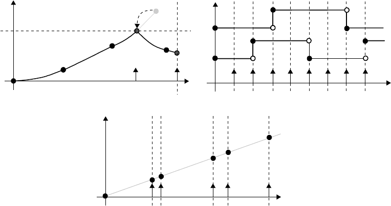
For the purposes of execution analysis, three categories of behavior over time can be distinguished, as
illustrated in Figure 15.10. These behaviors correspond to those shown in the power window example in
Figure 15.3.
In Figure 15.10(a), a behavior is shown that evolves continuously in time. This evolution is typically
modeled by differential equations and the traces are generated using numerical solvers. In Figure 15.10(a),
there is a time event that occurs at the point in time that is marked by the dashed vertical. A state event
is generated at the point in time when the continuous-time behavior, the solid line, exceeds the dashed
horizontal. When the threshold is exceeded, it is backtracked to the earliest point in time where this
occurred, indicated by the dashed arrow. The events are indicated by vertical solid arrows.
Hybrid Dynamic Systems: Modeling and Execution 15-13
t
(a)
t
(b)
t
(c)
FIGURE 15.10 Different types of execution. (a) Continuous time (b) discrete time and (c) discrete event.
In Figure 15.10(b), two signals are shown: (i) the top signal has a period of 4 (ms) with an offset of
3 (ms) and (ii) the bottom signal has a period of 3 (ms) and an offset of 2 (ms). Such behaviors only
contain time events that are of a periodic nature. This is typical in the design of an embedded controller,
where the system operates at a fixed sample time, the base rate, and the different aspects of the control
may execute at the fast base rate or have a sample time that is an integer multiple of the base rate. For the
signals in Figure 15.10(b), the base rate is 1 (ms). Synchronous languages such as Lustre (Halbwachs et al.,
1991) have been specifically designed to handle this class of systems.
In Figure 15.10(c), a behavior with only time events is shown, but the events are not periodic. Such
behaviors are typical in network modeling, where the time in which a packet arrives is variable as is the time
it takes to move the packet through a network. Another application is the modeling of the task scheduling
on a microprocessor network, where events occur when a task is completed. This time is typically variable
and the execution may even be preempted by higher priority tasks, resulting in further variability of the
execution time.
15.4.3 Time-Driven Execution
In a time-driven execution, a numerical solver is applied that governs the advance of time. The numerical
solver is typically provided with a set of differential equations, a start time, a set of initial states, a set of
input values, and a stop time. It then attempts to solve the differential equations to generate a trace of
numerical values for the states from the start time to the stop time. This trace may consist of any number
of steps and corresponding integration points.
The trace is generated by the numerical solver computing the size of a step in time to take, based on
the time gradients of the differential equations, as, for example, in Eq. (15.9). If there is a steep gradient
because of the fast changes in the state values, small steps are taken, whereas when the behavior changes
relatively slowly, larger steps are taken.
The stop time is either taken to be the end time of the requested simulation, or, in case there are time
events, the first of such an event is provided as the stop time. If only time events are present, and they are
statically known, then a schedule for execution can be precompiled. This is the case if all of the events are
periodic in nature. The greatest common denominator of all the different sample times is determined and
each of the events are executed at an integer multiple of this base rate.
