Ellis,J. Pressure transients in water engineering, A guide to analysis and interpretation of behaviour
Подождите немного. Документ загружается.

of any backfill is ignored in unconstrained conditions. Where a
compacted backfill is involved, the properties of fill have an important
influence on behaviour but the short-term effect of pipe ovalisation on
buckling pressure could also be included as outlined in the following
section.
462
210
200
190
180
170
160
150
140
130
120
110
100
90
80
70
60
50
40
30
20
10
0
Internal
p
ressure head
(
mWG
)
–10 0 10 20 30 40 50
Acoustic wavespeed a (m/s)
HDPE pipes
SDR = 26
c
2
= 6
Di = 0.04
SDR = 26
c
2
= 6
Di = 0.02
SDR = 17.6
c
2
= 6
Di = 0.04
SDR = 17.6
c
2
= 6
Di = 0.02
SDR = 26
c
2
= 2
Di = 0.02
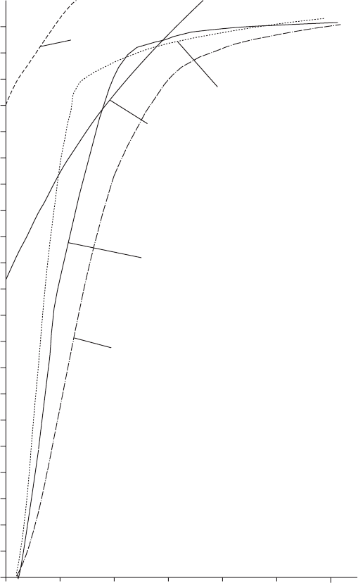
Fig. 22.4. Wave speed as a function of deformation
Pressure transients in water engineering

22.8 Short-term elastic buckling under hydraulic transient
effects
22.8.1 Unconstrained conditions
If the pipe is installed in air, water or in very soft soils such as wet clay
which provide little support, critical pressure becomes:
p
k
¼ 24:0 0:7E
ð0Þ
s
3
=ð12D
3
m
Þ=ð1
2
Þ
¼ 2ð0:7E
ð0Þ
Þðs=D
m
Þ
3
=ð1
2
Þð22:31Þ
22.8.2 Constrained conditions
If flexible pipes are exposed to a sudden negative pressure, the risk of
buckling can be calculated according to the following formula, provided
that the pipes are surrounded by granular soil which can give elastic
support to the pipe.
In studies of GRP pipe, Carlstrom (1981) introduced a reduction
factor for the stabilising effect of the soil modulus into the equation
for critical pressure, giving:
p
k
¼ð1 "
f
D
m
=sÞ
1:5
p
f32E
0
t0:7E
o
s
3
=ð12D
3
m
Þg ð22:32Þ
where ¼ 1 p=ðp þp
exð50Þ
Þ, p being the transient vacuum pressure
within the pipe and p
exð50Þ
the long-term vertical pressure on the
pipe. Long-term pipe stiffness ¼ 0:7E
o
s
3
=ð12D
3
m
Þ has been adopted as
the pipe may be more prone to buckle in the longer term when subject
to the same pressure transient. E
o
is the initial flexural circumferential
modulus.
p
exð50Þ
¼ Cg
s
B
where
s
is the weight of soil/m
3
and Table 22.5 provides some typical
values of
s
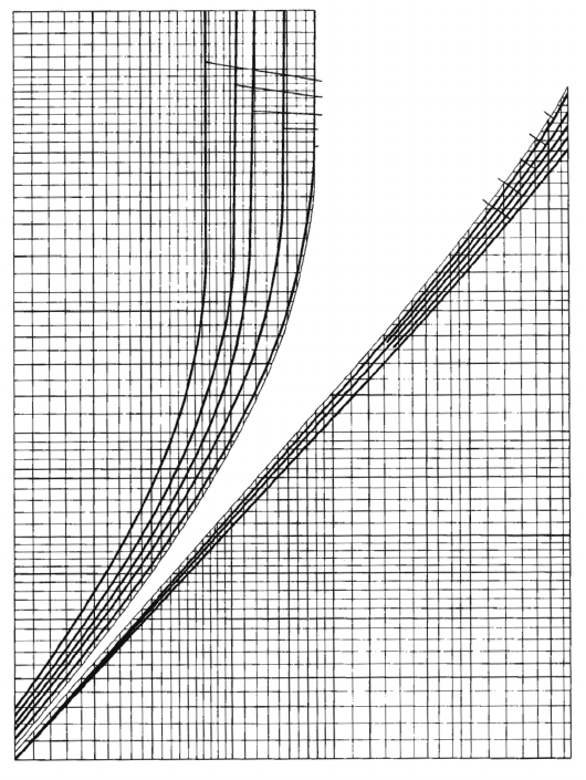
. Cg may be obtained from Fig. 22.5.
Carlstrom (1981) considered friction between the soil prism and the
surrounding fill as one component and friction between the native
material forming the trench wall and the neighbouring fill as a second
463
Table 22.5.
s
v. soil type
Soil type Granular/
non-cohesive
Stony/
sandy
Wet—
loamy
Clay/heavy
loam
Water-
saturated clay
s
=
water
1.7 1.9 2.0 2.1 2.2
Flexible pipe
component
r
, so that the vertical weight of overburden was modified
by a factor
r
. He also considered that over time the vertical pressure
would increase and so he proposed use of the factor ð1 þ Þ=
2ð1 þ
r
Þ=2 in compensation for long-term effects so that vertical
pressure was given by:
P
exð50Þ
¼ð1 þÞ=2ð1 þ
r
Þ=2ðp
s
þ p
t
p
wu
p
w
Þ
where p
s
is the pressure from overburden on the pipe, p
t
is pressure due
to traffic loading, p
wu
is uplift pressure due to groundwater, and p
w
is
internal water pressure.
464
40
30
20
15
10
9
8
7
6
5
4
3
2.5
2
1.5
0.1 0.15 0.2 0.3 0.4 0.5 0.6 0.8 1.0 1.5
1 1.5 2 3 4
H/B
H/B
a
b
c
d
e
a
2
1.5
1
0.9
0.8
0.7
0.6
0.5
0.4
0.3
0.25
0.2
0.15
0.10
b
c
d
e
Cg
C
g
Fig. 22.5. C
g
as a function of depth of cover/trench width
Pressure transients in water engineering
Much of the foregoing is based upon the assumption of a generally
elliptical deformation with y=h ¼ 0:91.
A number of studies have been carried out of flexible pipe defor-
mation behaviour using finite-element analysis of the soil structure.
The possibility exists of coupling hydraulic transient analysis with the
numerical analysis of soil behaviour to provide a more detailed picture
of deformations.
22.9 Application of a flexible pipe model
Some examples have been included to illustrate the effects of pipe
flexibility upon the propagation of pressure transients. Different types
of simple pipeline configuration have been considered.
22.9.1 Long horizontal pipeline
The first case considers a long horizontal pumping main. Overall
length of the pipeline is 12.5 km and an overburden or external
loading equivalent to 2.5 mWG has been included.
Pipe bedding was included which offered some lateral support to a
deforming pipe. Initial ovality was set at 2% and gas release at low
pressure was included. The suction well level was set at þ0.0 mWG
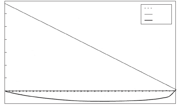
and discharge elevation was þ1.0 mWG. Figure 22.6 shows predicted
465
0 1000 2000 3000 4000 5000 6000 7000 8000 9000 10 000 11 000 12 000
Chaina
g
e (m)
Series 1
Series 2
Series 3
Horizontal flexible pipeline. con = 1.0, del/D = 2%, h
b
= 12.3, gas included
Elevation (mAD)
70
60
50
40
30
20
10
0
–10
Fig. 22.6. Envelope curves for horizontal pipe and 2% deflection ratio
Flexible pipe
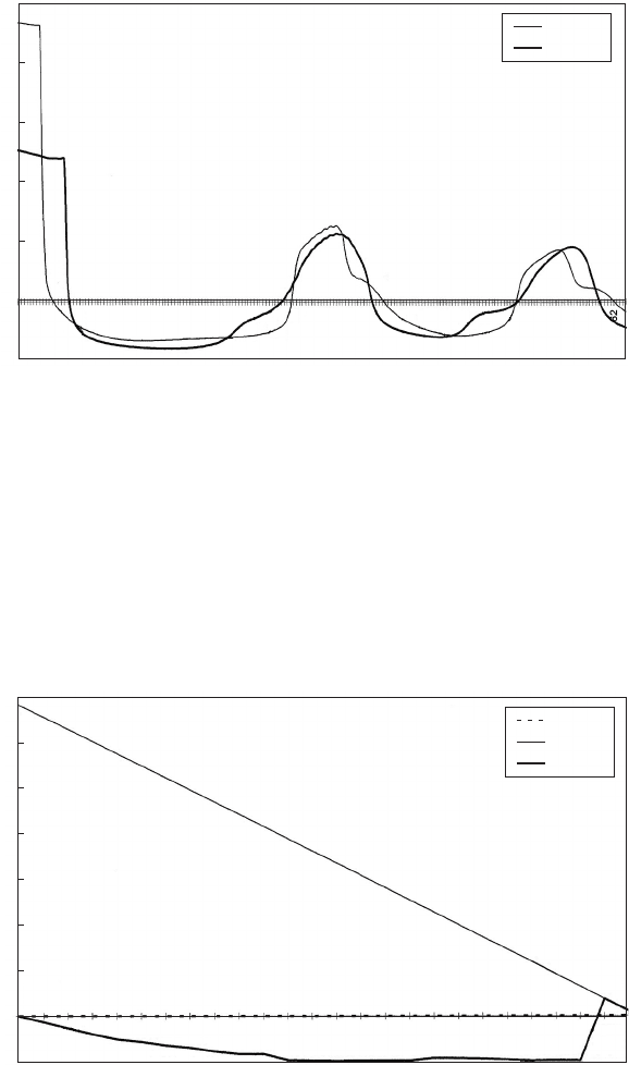
minimum head following a pumping failure. Maximum head is that of
steady pumping. In Fig. 22.7 changing head at the pumping station
and approximately halfway along the main are shown. A significant
amount of damping is evident in these results. If gas release is ignored
and the pipe has the same trench support as before, the minimum head
along the main after pump trip falls to a greater extent and buckling
occurs at chainage 11.5 km as depicted in Fig. 22.8. The model was
466
Time (s)
Horizontal flexible pipeline. con = 1.0, del/D = 2%, h
b
= 12.3
Head (mAD)
50
40
30
20
10
0
–10
2.46
19.68
36.90
54.12
71.34
88.56
105.78
123.00
140.22
157.44
174.66
191.88
209.10
226.32
243.54
260.76
277.98
295.20
312.42
329.64
346.86
364.08
381.30
398.52
415.74
432.96
450.18
467.40
484.62
Series 1
Series 2
Fig. 22.7. Head variation for horizontal pipe after pump failure
Chaina
g
e (m)
Series 1
Series 2
Series 3
Horizontal flexible pipeline. con = 0.9, del/D = 2%, h
b
= 12.3, no gas
Elevation (mAD)
0 1000 2000 3000 4000 5000 6000 7000 8000 9000 10 000 11 000 12 000
70
60
50
40
30
20
10
0
–10
Fig. 22.8. Envelope curves showing prediction of pipe buckling
Pressure transients in water engineering
set to terminate computations in the event of a pipe collapse. Where
the buckling limit is below the gas release level then the formation of
gas- or vapour-filled cavities will inhibit any further fall in head and
so internal pressure should not reach the level at which buckling occurs.
22.9.2 Descending outfall
The second example considers an idealised outfall similar to one of the
case studied by Larsen (1976). The pipeline descends uniformly over a
distance of 3 km. Pumping is used to overcome resistance with the
suction well level set at þ0.0 mAD. The pipeline is at 30.0 mAD at
its discharge point. An initial uniform eccentricity of 2% was adopted.
Gas release was represented and the pipeline was without lateral
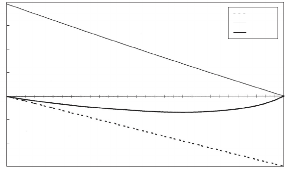
support. After pump trip the minimum head shown in Fig. 22.9 was
predicted. The damping effect shown is essentially due to the pipe flex-
ibility as positive internal pressures preclude gas release. Appreciable
damping of the pressure wave is also evident in this figure.
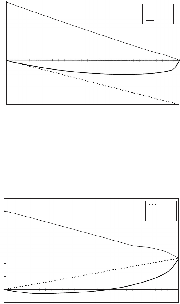
If the pipeline is supported by stiffeners, flexibility is reduced. After
trip, the minimum head along the main falls to a greater extent than
before, as shown in Fig. 22.10. Greater amplitude of head variation
also occurs than without supports, again indicating a smaller amount
of damping in this stiffer pipeline.
Chaina
g
e (m)
Series 1
Series 2
Series 3
Descending flexible pipeline. con = 6, del/D = 2%, h
b
= 12.3, gas c = 0.000 01
Elevation (mAD)
0
100
200
300
400
500
600
700
800
900
1000
1100
1200
1300
1400
1500
1600
1700
1800
1900
2000
2100
2200
2300
2400
2500
2600
2700
2800
2900
3000
40
30
20
10
0
–10
–20
–30
Fig. 22.9. Envelope curves for descending outfall after pump failure and 2%
deflection ratio
Flexible pipe
22.9.3 Uniformly rising main
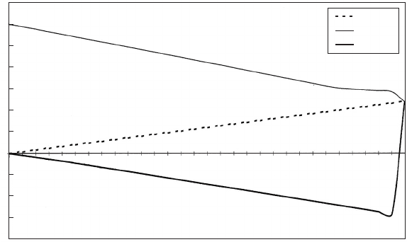
A further example studied a uniformly rising pipeline of length 3 km.
This was also one of the configurations examined by Larsen. If the pipe-
line is supported along its length then following a pump trip, minimum
head is able to fall to a considerable extent as shown in Fig. 22.11. If the
468
Chaina
g
e (m)
Series 1
Series 2
Series 3
Descending flexible pipeline. con = 1.0, del/D = 2%, h
b
= 12.3, gas c = 0.000 01
Elevation (mAD)
0
100
200
300
400
500
600
700
800
900
1000
1100
1200
1300
1400
1500
1600
1700
1800
1900
2000
2100
2200
2300
2400
2500
2600
2700
2800
2900
3000
40
30
20
10
0
–10
–20
–30
Fig. 22.10. Enve lope curves for descending outfall after pump failure and with
stiffeners
Chaina
g
e (m)
Series 1
Series 2
Series 3
Rising profile. Flexible pipeline. con = 1.0, del/D = 2%, h
b
= 12.3
Elevation (mAD)
35
30
25
20
15
10
5
0
–5
0
100
200
300
400
500
600
700
800
900
1000
1100
1200
1300
1400
1500
1600
1700
1800
1900
2000
2100
2200
2300
2400
2500
2600
2700
2800
2900
3000
Fig. 22.11. Rising main, envelope curves with pipe stiffeners
Pressure transients in water engineering
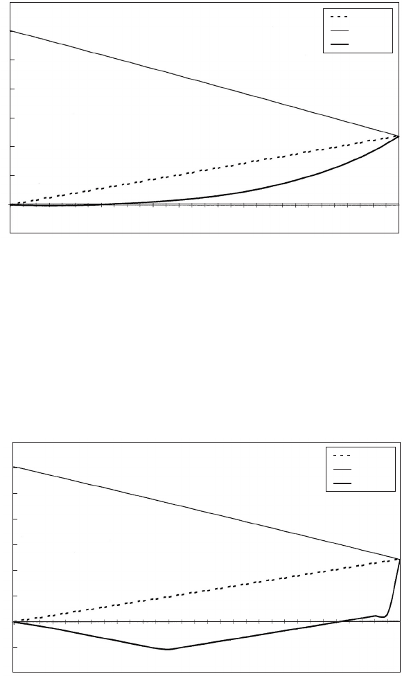
pipeline is unsupported, damping due to shape change is greater and
minimum head after trip does not fall to the same extent as before,
as illustrated in Fig. 22.12. If a rigid pipe is assumed, the minimum
head after pump failure is determined by vapour cavity formation, as
illustrated in Fig. 22.13, while if gas release and vapour cavity formation
469
Chaina
g
e (m)
Series 1
Series 2
Series 3
Rising profile. Flexible pipeline. con = 6.0, del/D = 2%, h
b
= 12.3
Elevation (mAD)
35
30
25
20
15
10
5
0
–5
0
100
200
300
400
500
600
700
800
900
1000
1100
1200
1300
1400
1500
1600
1700
1800
1900
2000
2100
2200
2300
2400
2500
2600
2700
2800
2900
3000
Fig. 22.12. Rising main, envelope curves for unsupported pipe
Chaina
g
e (m)
Series 1
Series 2
Series 3
Rising profile. Rigid pipeline. con = 0.0, del/D = 2%, h
b
= 12.3
Elevation (mAD)
35
30
25
20
15
10
5
0
–5
–10
0
100
200
300
400
500
600
700
800
900
1000
1100
1200
1300
1400
1500
1600
1700
1800
1900
2000
2100
2200
2300
2400
2500
2600
2700
2800
2900
3000
Fig. 22.13. Rising main, envelope curves for rigid pipe and gas release
Flexible pipe
are both ignored, the minimum head falls to a much greater extent, as
depicted in Fig. 22.14.
The previous two examples considered produced predictions closely
in line with Larsen’s results when similar pipe properties were used. This
finding would indicate that it is quite feasible to utilise a fixed grid
computational scheme for such studies as well as a variable wave
speed scheme.
22.9.4 Pipeline of differing properties
Many pipeline networks are made up of a set of pipelines, each of which
has different properties. If flexibility of a pipe is considered then even if a
pipe of uniform characteristics is considered — that is, constant diameter,
material and wall thickness — a radical change in the pipe support
arrangement may be sufficient to produce a different response from
individual sections of a main. An outfall system may comprise a landward
section of pipeline which is laid in a trench with well-compacted backfill
and a seaward section which is essentially unsupported. The landward
stretch of main is unlikely to deform to the same extent as the seaward
element under changing pressure.
As an example, consider a pumped outfall having a horizontal land-
ward pipeline section of length 3.0 km and invert level þ1.0 mAD,
470
Chaina
g
e (m)
Series 1
Series 2
Series 3
Rising profile. Rigid pipeline. No air content. con = 0.0
Elevation (mAD)
35
30
25
20
15
10
5
0
–5
–10
–15
–20
0
100
200
300
400
500
600
700
800
900
1000
1100
1200
1300
1400
1500
1600
1700
1800
1900
2000
2100
2200
2300
2400
2500
2600
2700
2800
2900
3000
Fig. 22.14. Rising main, envelope curves for rigid pipe and no gas release
Pressure transients in water engineering
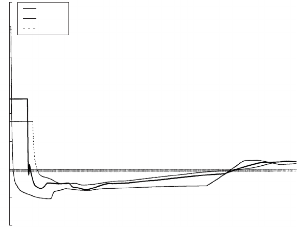
leading to an embankment or seawall at level þ2.5 mAD. A seaward
section extends for a further 3.0 km, initially falling at a gradient
1:200 and then more steeply at 1:100 to a final discharge level of
14.0 mAD. Pumping station suction well level was at 3.0 mAD.
After pump trip, head falls steeply at the pumping station and for an 8 s
interval Fig. 22.15 shows rarefaction waves propagating along the
landward section with little damping evident, producing a minimum
pressure of around 8.0 mAD. Once over the seawall and into the
descending outfall section, noticeable damping occurs. Envelope curves
for the 6 km main show most clearly the effects of the different responses
of the two sections of main. The relatively stiff landward section allows a
substantial fall in head after trip. Within the seaward section, damping
inhibits the development of low pressures to an appreciable extent
(Fig. 22.16).
The cases considered were primarily used to demonstrate the
feasibility of carrying out computations for deforming pipelines under
changing transient pressure. Including what appears to be a significant
effect within day-to-day investigations, as a matter of routine is con-
sidered worthwhile. Obtaining the necessary information to allow
471
Time
(
s
)
d/s PS
Seawall
Outfall
Head (mAD)
30
25
20
15
10
5
0
–5
–10
Fig. 22.15. Composite system, head variations after pump trip
Flexible pipe
