Ellis,J. Pressure transients in water engineering, A guide to analysis and interpretation of behaviour
Подождите немного. Документ загружается.

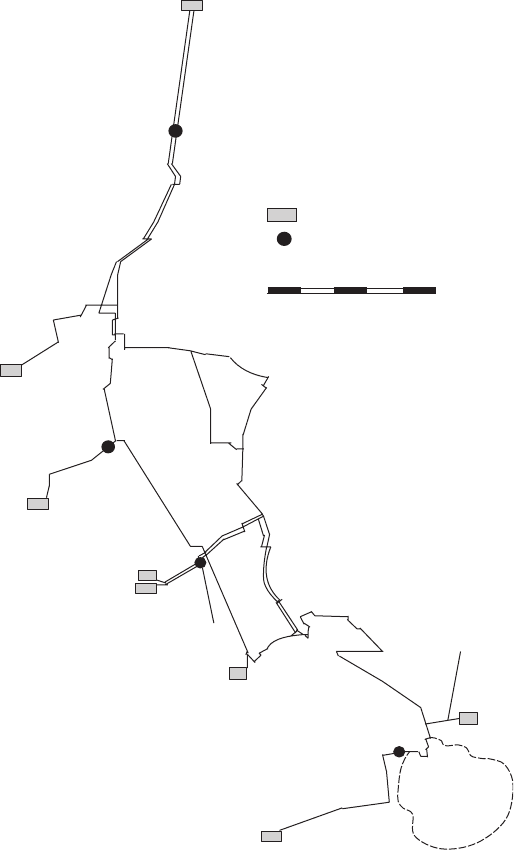
limit of C62. From this pumping station a rising main extends to Yearby
Reservoir at an elevation of 85.675 mAOD. From Yearby a series of
pumping stations and pumping mains serves substantial areas of the
North York Moors. Between the steelworks branch and Kirkleatham
PS lies the Redcar residential area served by a set of branch connections
482
Longnewton TWL = 61 mOD
C53 840f C67 1016f
Uplands PS
Tank or reservoir
Pumping station
C62 600f conduit No. and diameter
5 km
C53
C67
C67
C67
C53
C53
C77 900f
300f
250f
C61 760f
C61
C66 381f
Booster PS
Maltby Grange
TWL = 63 mOD
C42 450f
C46 760f
C56 530f
C45
760f
Hemlington Park
TWL = 46.65 mOD
C48
450f
C47
380f
C43
380f
C69
914f
Longbank
TWL = 84.15 mOD
Nunthorpe
South Lakenby TWL = 50 mOD
C51 450f
C62 600f
Steel 250f
BS tank
Kirkleatham Lane PS
Booster PS
AC 600f
Yearby TWL = 85.675 mOD
Redcar
distribution
zone
Fig. 23.7. Distribution system leading to Kirkleatham Lane pumping station
Pressure transients in water engineering
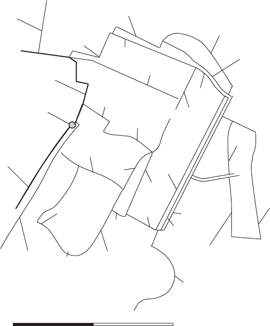
from C62. Figure 23.8 shows the networks of pipelines supplying Redcar
as modelled in this study. Branches from C62 comprise two DN 150
mains along Corporation Road, a DN 457 main laid along Trent
Road and a DN 250 pipeline into Kirkleatham Lane itself.
Following earlier studies, a pressure vessel was installed on the down-
stream side of Kirkleatham Pumping Station to protect the rising main
to Yearby from sub-atmospheric pressures. On pump start-up there is an
upsurge on the downstream side of the pumps and a drawdown on the
suction side. The presence of the pressure vessel on the delivery side of
the pumps allows a relatively smooth and gradual rise in pressure to
occur. In contrast, on the suction side the drawdown is very abrupt.
Similarly, when Kirkleatham pumps are switched off there is a
smooth and controlled decline in the head downstream of the pumps
483
250f to
BS Redcar
2 ¥ 150f
High St West 150f
High St 150f
Esplanade 150f
Coatham Rd
228f
Corporation Rd
150f
C62 600f from
South Lakenby
Trent Road
457f
Troutbeck Rd
457f
200f
West Dyke Rd
228f
West Dyke Road
228f
Race
course
380f
150f
150f
150f
150f
380f
457f
150f
250f
Coast Rd
150f
Kirkleatham Lane PS
Redcar Lane
150f
200f
Laburnum Rd
150f
Roseberry Road
150f
Low Farm Drive
150f
Kirkleatham Lane
250f
0 1 2 km
600f AC to
Yearby Res.
Fig. 23.8. Redcar distribution area (simplified)
Amplification of transient pressures
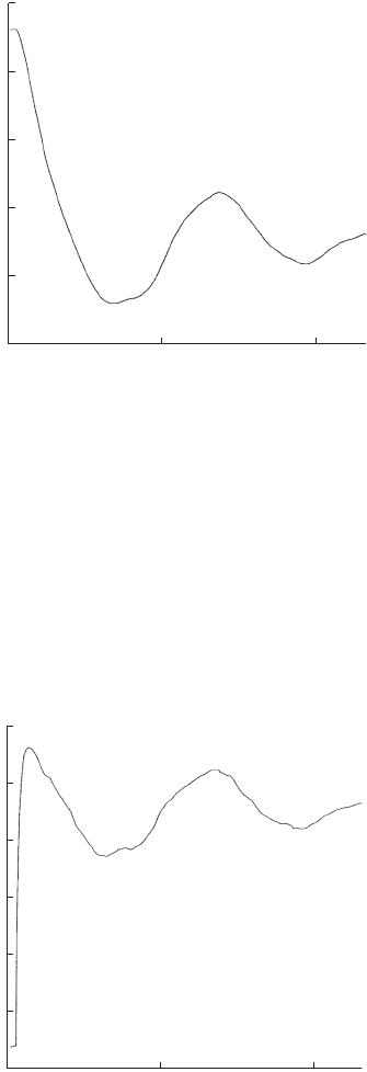
regulated by the pressure vessel (Fig. 23.9), while on the suction side
pressure rises sharply (Fig. 23.10).
23.5.2 System modelling
With an extensive network of large-diameter trunk mains to consider,
it might be tempting to ignore or greatly simplify the network of
smaller-diameter distribution pipes. For example, residential demands
484
0.00 0.25 0.5
110
100
90
80
70
Head (mAOD)
Time (min)
Fig. 23.9. Head downstream of Kirkleatham Lane pumping station after pump trip
0.00 0.25 0.5
Head (mAOD)
Time
(
min
)
90
80
70
60
50
40
Fig. 23.10. Head upstream of Kirkleatham Lane pumping station after pump trip
Pressure transients in water engineering
might be represented by a single drawoff. While it may be reasonable
to suppose that the transient response of the distribution area will
not have important consequences for the trunk main system as a
whole, the converse is not necessarily true. Surge behaviour within
the network of larger mains can have an important influence upon
behaviour within the smaller mains of the distribution system.
23.5.3 Recorded pipe bursts and pressure extremes
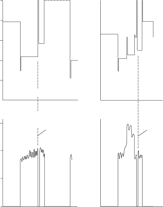
Within the distribution system of Fig. 23.8 a number of bursts were
recorded. Figure 23.11 shows head and flow just upstream of the
485
*
*
* *
*
Metres
50
40
30
20
10
0
30
20
10
0
Time
Time
3 bursts 1 burst
*Pressure surge at pump stop exceeds 50 metres
Kirkleatham PS
outflow – MLD
Fig. 23.11. Head recordings at Kirkleatham indicating pipe bursts had occurred
Amplification of transient pressures
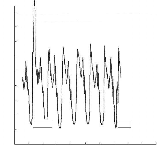
pumping station. When head rises and flow falls to zero this indicates
that pumps have been tripped. Three bursts were recorded on one
occasion within the distribution zone and a further single burst after
a subsequent pump trip. Flow recordings with the distribution system
(Fig. 23.12) noted an abrupt flow increase which correlated with the
pipe bursts. Figure 23.11 shows the predicted steep head increase
upstream of the pumping station following pump trip, with a
maximum head of around 86 mAOD. Within the distribution system
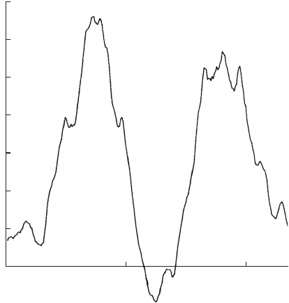
along Redcar Lane, the corresponding predicted head variation is
shown in Fig. 23.13, with maximum head exceeding 150 mAOD.
Minimum head was also predicted to fall below atmospheric pressure,
which may interfere with sensitive equipment such as that used for
home dialysis which draws supplies direct from mains.
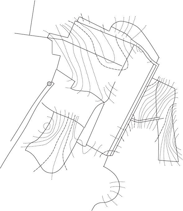
Predicted peak pressure within the distribution system, following
trip of Kirkleatham pumps, is shown in Fig. 23.14 in the form of
486
hr:mn 00:00
MT/94 26/10 27/10 28/10 29/10 30/10 31/10 01/11 02/11 03/11 04/11
90
80
70
60
50
40
30
20
10
0
Flow (l/s)
Time
3 bursts
burst
1
Fig. 23.12. Time history of velocity
Pressure transients in water engineering
contours of maximum piezometric level. These show a steady increase
in maximum pressure with distance into the network from the trunk
main. Maximum pressure within the system can exceed about 150%
of the peak pressure developed on the suction side of the pumping
station. These peak pressures correlated with the observed pipe bursts
which occurred in the network.
This example serves to illustrate that when a transient initiated
within a larger diameter of pipe is able to propagate into a system of
smaller pipes then the potential exists for the amplitude of pressure
fluctuations to increase substantially. In the case examined, one
remedy studied was to include a pressure vessel on the suction side of
the pumping station. This vessel attenuated the upsurge following
pump trip and allowed the effects of wave reflections within the
distribution system to reduce the severity of both maximum and
minimum pressures. The potential for pressure waves created at the
steelworks tank inlet valve was also considered, with the simplest
remedy here being control of valve stroke time in order to produce
sufficiently gradual rates of flow change and thus modest pressure
gradients.
487
Head in Redcar Lane
Head (mAOD)
Time (min)
0.00 0.25 0.5
160
140
120
100
80
60
40
Fig. 23.13. Time history of head
Amplification of transient pressures
23.6 Wellfield transients
23.6.1 Collector pipeline system
The collector pipeline systems of many wellfields consist of pipes having
different diameters. The flow cross-section of each pipeline in the
network will be related to the number of wells contributing to that
pipe and their combined flow. It will therefore be the case that smaller
pipes will be used in the parts of the network more remote from a
receiving reservoir. Figure 23.15 shows the plan arrangement of an
extensive wellfield in the United Arab Emirates (UAE). Pipe diameter
488
10.1
11.0
12.0
13.0
13.5
13.9
10.8
10.5
10.6
10.7
10.6
14.0
15.0
15.7
14.0
13.0
12.0
11.0
10.8
10.9
11.0
12.0
12.5
12.9
11.5
11.4
11.3
11.2
11.1
14.5
15.5
Fig. 23.14. Contours of maximum pressure following pump trip
Pressure transients in water engineering

489
Reservoir compound
DN 600 DI
W-105
W-103
W-106
W-111
W-113
Isolating valve ‘A’
Isolating valve ‘B’
Motorised valves
Non-return valve
Line 2
Line 3
Line 4
Line 5
Line 1
Line 1
Line 6
0 1 2 3 km
W-49
Wellhouse
DN 100 DI
W-1
W-123
W-125
W-124
Fig. 23.15. UAE wellfield configuration
Amplification of transient pressures
close to the reservoir was 600 mm while at the extremities of the system,
for instance near to well number 1, diameter was 100 mm.
23.6.2 Borehole and wellhouse configuration
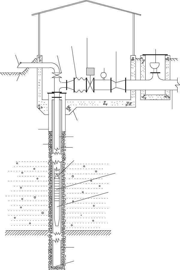
A typical wellhouse arrangement may be as illustrated in Fig. 23.16.
In this case a check valve was located directly on top of the multi-
stage borehole pump, thus maintaining the riser full of water when
the pump is idle. In many instances underground water is being
mined with little recharge to replenish the store of water. Over time
a substantial variation in aquifer water level will occur, not only due
to the development of a cone of depression around each well but
also as a consequence of the long-term depletion of the resource
(Fig. 23.17). The delivery head where flow leaves the wellhouse is a
function of the receiving reservoir level and also depends upon flows
from other operating pumps contributing to the same system of
collector pipelines. The often substantial change in pump operating
head requires some means of regulating flow. A flow regulating valve
can be fitted in the wellhouse to ensure that short-term variations in
discharge are restricted to design values.
Longer-term lowering of water level in the aquifer may require pumps to
be uprated to accommodate the increased lift. Additional impellers may
be added to individual pumps, with the motor having been chosen to
suit the anticipated maximum number of stages. These measures to
control maximum discharge from a borehole are designed to avoid over-
pumping which could damage the well. Control of discharge also has
beneficial effects as far as pressure transient behaviour is concerned. It
should be noted that not all wellfields include wellhead flow regulation.
Where the well is able to accommodate the flow developed when aquifer
level is at its maximum without damaging the well then any transient
investigation should consider this peak flow condition.
An air valve may also be included at the wellhead and the possible
operation of this valve during a transient event should be considered.
23.6.3 Wellfield operating conditions
The wellfield illustrated in Fig. 23.15 is intended to operate as two
separate pumping systems. The isolating valves A and B are normally
closed, with all wells connected to collector main No. 1 known as
GROUP I and these wells feeding into collector mains No. 2, No. 3,
No. 4, No. 5 and No. 6 known as GROUP II. In emergency
490
Pressure transients in water engineering
circumstances when one of the DN 600 mains downstream of valve A is
out of service, this valve can be opened to allow flows from both groups
of pumps to reach the reservoirs via a single DN 600 line. When a
collector main is isolated upstream of point A then valve B is opened
491
Flap valve
Ground level
Gate valve
Compensator
Control valve
electrically operated
Pressure
gauge
Flow meter
Air valve
Branch pipeline
Annular concrete plug
Stand pipe
Gravel packing
Casing
Riser pipe from pump
Non-return valve
Multi-stage pump
Motor
Aquifer
Aquifer
Bail bottom
Sump pipe
Clay (impervious)
Fig. 23.16. Typical well arrangement
Amplification of transient pressures
