Duan C.G., Karelin V.Y. Abrasive Erosion and Corrosion of Hydraulic machinery
Подождите немного. Документ загружается.

364
Abrasive Erosion and Corrosion of Hydraulic Machinery
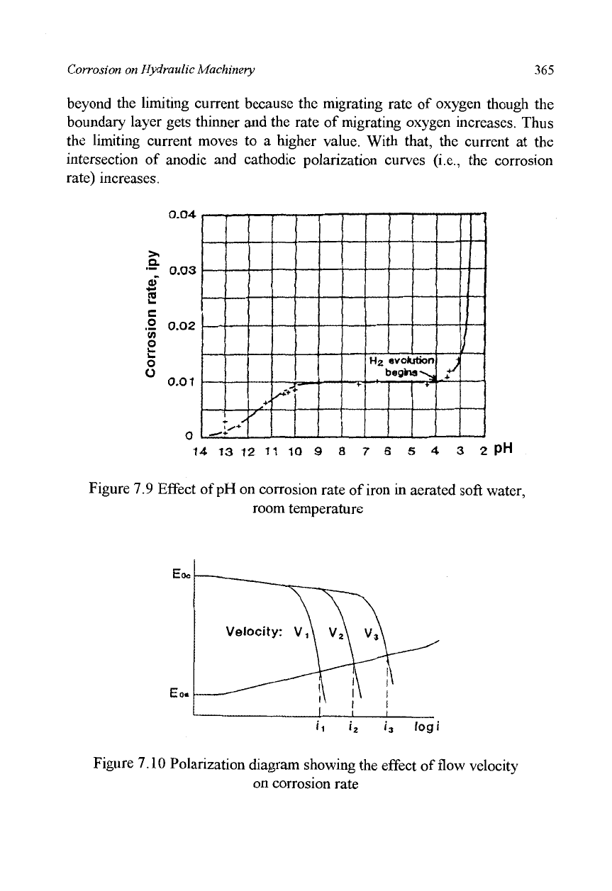
The result is shown in Figure 7.7. The corrosion activity can be classified
into three categories according to pH. In a range of pH5 to pHIO, the
corroded surface is covered with by a film of ferrous oxide through which
oxygen migrates to the surface of the mild steel and corrosion continues. On
the surface of the steel, the pH is always 7.5 regardless of the pH of the
electrolyte. Thus the rate of corrosion becomes constant independent of the
pH out side the film. In acidic environments where the pH is less than 4, the
ferrous oxide film on the surface is dissolved away and the steel is directly
exposed to the electrolyte. In addition to oxygen reduction, hydrogen gas is
generated and facilitates the cathode reaction, hydrogen gas is generated and
facilitates the cathode reaction. Thus, the corrosion rate is greatly increased.
In alkaline environments where the pH is greater than 10, a more stable and
fine protective layer is formed than in the neutral environments and corrosion
rate is slowed significantly.
Let us compare the experimental results of Figure 7.9 with the theory of
Pourbaix diagram (Figure 7.8). Firstly, as to the effect of pH on hydrogen gas
evolution the experimental result may be judged consistent with the theory
because the corrosion potential of a mild steel in neutral and acidic
environments is usually -0.4V to -0.5V, which is lower than the potential of
a hydrogen electrode in an acidic region. In such conditions, the theory
predicts hydrogen gas evolution as was already pointed out in the preceding
paragraph.
Secondly, the experimental result that the corrosion rate in an alkaline
environment declines due to the stable oxide film on the metal surface is well
illustrated in the Pourbaix diagram.
Thirdly, as to the effect of fluid flow velocity on corrosion rate,
Whitman's experiment described above was conducted in a flowing
electrolyte. Generally speaking, corrosion increases with an increase in the
velocity of the electrolyte flowing over the metal surface. Theoretically, the
velocity of flow does not influence equilibrium potential, so we cannot explain
with the Pourbaix diagram why a higher flow velocity causes larger
corrosion. The reason for that phenomenon is explained as follows in the
polarization diagram. The cathode polarization curve in Figure 7.10
represents the polarization of oxygen reducing reactions; the polarization
curve has two parts, one with a gentle slope due to the activation polarization
and the other with a steep one due to the effect of concentration polarization.
As explained in equation (7.14) presented earlier, the current cannot increase
Corrosion on Hydraulic Machinery
365
beyond the limiting current because the migrating rate of oxygen though the
boundary layer gets thinner and the rate of migrating oxygen increases. Thus
the limiting current moves to a higher value. With that, the current at the
intersection of anodic and cathodic polarization curves (i.e., the corrosion
rate) increases.
0.04
" 0.03
1
.2 0.O2
o
o
0.01
4
t
-—f
*■
/'
r"
+.
I
H2 evolution
begins-sy
J
!
14 13 12 11 10 9 8 7 6 5 4 3 2 PH
Figure 7.9 Effect of pH on corrosion rate of iron in aerated soft water,
room temperature
Figure 7.10 Polarization diagram showing the effect of flow velocity
on corrosion rate
366
Abrasive Erosion and Corrosion of Hydraulic Machinery
7.2.3 Cathodic Protection
The Pourbaix diagram in Figure 7.8 presents the possibility that iron at a
potential of -0.5V in an electrolyte of pH4 with an iron ion concentration of
10"
mol/1 at a temperature of 25°C is likely to be corroded, but it does not
tell us its corrosion rate. On the other hand, it does tell us that we can stop the
iron corrosion by lowering the potential below -0.62V. Then, the iron
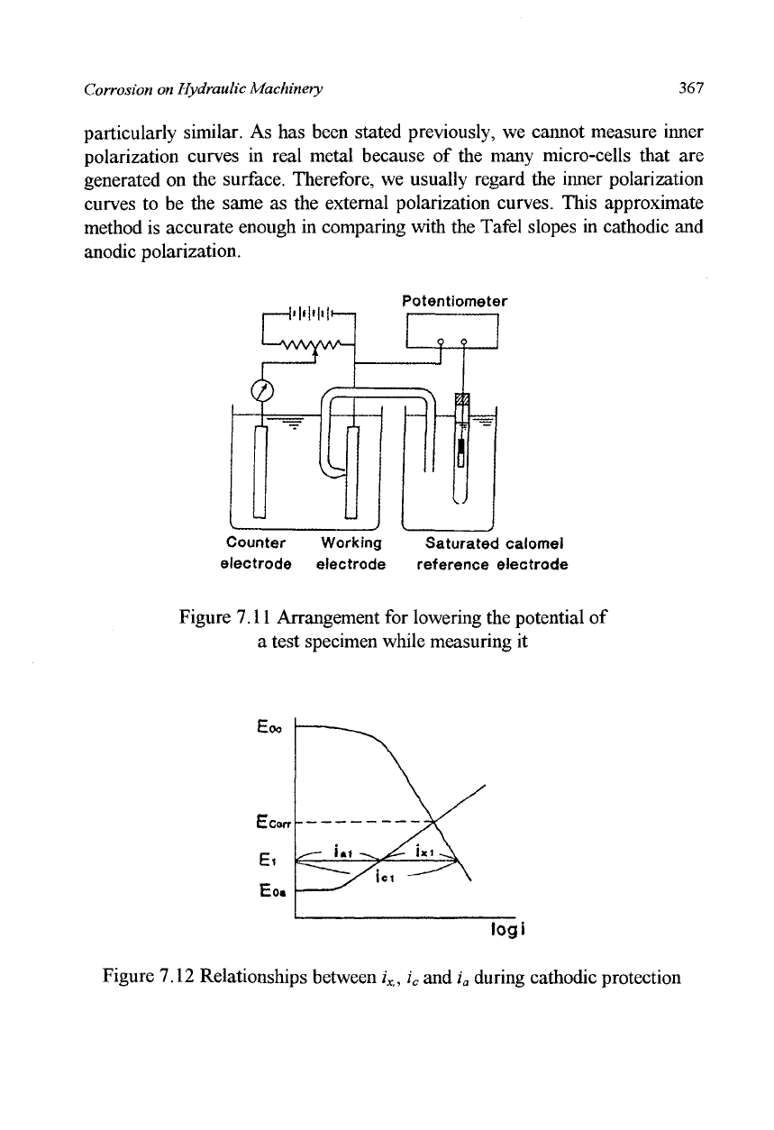
becomes immunity and corrosion will cease. Figure 7.11 shows an
arrangement for lowering the potential of the test specimen while measuring
it, and Figure 7.12 shows the relationship between the current and potential
during the operation. In Figure 7.11, for measuring the potential of the test
specimen, a saturated colonel reference electrode is used rather than hydrogen
one because it is easier to handle. This electrode shows +0.24V at 25°C
(assuming the hydrogen electrode as the zero standard). In order to lower the
potential of the test specimen, an external current is applied to the test
specimen from the counter electrode made of inert material such as platinum
or graphite carbon. Before being supplied with current, the test specimen is
undergoing natural corrosion at a potential of
E
C00
r
and with the corrosion
current of
i
corr
.
On supplying the current to the test specimen, it flows in the
opposite direction of
the
anodic current which is due to the dissolving of iron,
and in the same direction as the cathodic current which is due to the reduction
of
oxygen.
Therefore, the external current supplied from the counter electrode
(through the electrolyte) to the test specimen decreases the anodic current and
increases the cathodic current. These changes in the currents at the cathode
and anode both lower the electrode potentials. Figure 7.12 indicates the
followings: when external current i
x
is applied, the cathodic current increases
from
icorr
to i
c
i, anodic current decreases from
i
corr
to /'„;. The potential lowers
itself from E
corr
to E
h
If
the
external current is increased further the potential
of the test specimen is lowered further to reach E
oa
which is the equilibrium
potential of anode. At this point the anodic current drops to zero and
corrosion stops. This is the principle of cathodic protection.
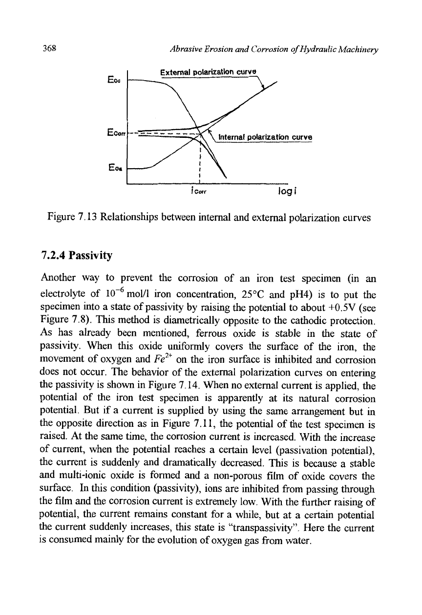
When we express the external current using the same axis as is used for
the cathodic or anodic currents, we obtain Figure 7.13. In this figure, an
external anodic current is also shown. The thick lines are external polarization
curves. As the horizontal axis is scaled in logarithms, the external polarization
curve almost coincides with the inner polarization curve (represented by the
thin line) when the current exceeds the
i
corr
-
The slopes of these curves are
Corrosion on Hydraulic Machinery 367
particularly similar. As has been stated previously, we cannot measure inner
polarization curves in real metal because of the many micro-cells that are
generated on the surface. Therefore, we usually regard the inner polarization
curves to be the same as the external polarization curves. This approximate
method is accurate enough in comparing with the Tafel slopes in cathodic and
anodic polarization.
Potentiometer
Counter Working Saturated calomel
electrode electrode reference electrode
Figure 7.11 Arrangement for lowering the potential of
a test specimen while measuring it
logi
Figure 7.12 Relationships between
i
Xi
,
i
c
and i
a
during cathodic protection
368
Abrasive Erosion and Corrosion of Hydraulic Machinery
External polarization curve
I
Coir
logi
Figure 7.13 Relationships between internal and external polarization curves
7.2.4 Passivity
Another way to prevent the corrosion of an iron test specimen (in an
electrolyte of 10
_6
mol/l iron concentration, 25°C and pH4) is to put the
specimen into a state of passivity by raising the potential to about +0.5 V (see
Figure 7.8). This method is diametrically opposite to the cathodic protection.
As has already been mentioned, ferrous oxide is stable in the state of
passivity. When this oxide uniformly covers the surface of the iron, the
movement of oxygen and Fe
2+
on the iron surface is inhibited and corrosion
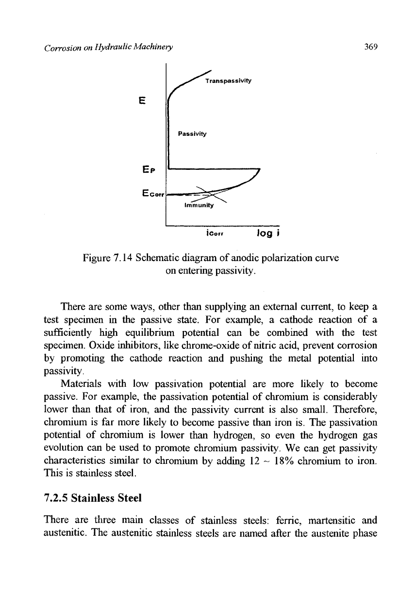
does not occur. The behavior of the external polarization curves on entering
the passivity is shown in Figure 7.14. When no external current is applied, the
potential of the iron test specimen is apparently at its natural corrosion
potential. But if a current is supplied by using the same arrangement but in
the opposite direction as in Figure 7.11, the potential of the test specimen is
raised. At the same time, the corrosion current is increased. With the increase
of current, when the potential reaches a certain level (passivation potential),
the current is suddenly and dramatically decreased. This is because a stable
and multi-ionic oxide is formed and a non-porous film of oxide covers the
surface. In this condition (passivity), ions are inhibited from passing through
the film and the corrosion current is extremely low. With the further raising of
potential, the current remains constant for a while, but at a certain potential
the current suddenly increases, this state is "transpassivity". Here the current
is consumed mainly for the evolution of oxygen gas from water.
Corrosion on Hydraulic Machinery 369
E
EP
CCorr
icorr Jog i
Figure 7.14 Schematic diagram of anodic polarization curve
on entering passivity.
There are some ways, other than supplying an external current, to keep a
test specimen in the passive state. For example, a cathode reaction of a
sufficiently high equilibrium potential can be combined with the test
specimen. Oxide inhibitors, like chrome-oxide of nitric acid, prevent corrosion
by promoting the cathode reaction and pushing the metal potential into
passivity.
Materials with low passivation potential are more likely to become
passive. For example, the passivation potential of chromium is considerably
lower than that of iron, and the passivity current is also small. Therefore,
chromium is far more likely to become passive than iron is. The passivation
potential of chromium is lower than hydrogen, so even the hydrogen gas
evolution can be used to promote chromium passivity. We can get passivity
characteristics similar to chromium by adding 12 ~ 18% chromium to iron.
This is stainless steel.
7.2.5 Stainless Steel
There are three main classes of stainless steels: ferric, martensitic and
austenitic. The austenitic stainless steels are named after the austenite phase
^S*^ Transpassivity
Passivity
immunity
370
Abrasive Erosion and Corrosion of Hydraulic Machinery
which is of face-centered cubic lattice and exists stable for pure iron between
910 and 1400°C only. By adding more than 8% of nickel to it, this phase can
exist stable or metastable at room temperature. The typical austenitic stainless
steel is the AISI (and JIS) type SUS 304 which is sometimes called 18-8 as it
contains 18% Cr, 8% Ni and the Fe. The stainless steels of this class are the
most reliable materials because they have the highest general corrosion
resistance, excellent heat resistance and free from cold shortness. They have,
however, some weak points in regard to pitting corrosion, crevice corrosion,
intergranular corrosion and stress corrosion cracking.
Pitting corrosion is initiated by the adsorption of anions (negative charged
ions),
particularly chloride ions, on the defect sites in the oxide film such as at
slag inclusions. The chloride ions can break the oxide film under a certain
condition and cause local dissolution. Once a pit has been formed, a "passive-
active cell" is set up; the inside surface for the pit is anode and the whole
oxide film surface outside the pit is cathode, which results in a high current
density at the very localized anodic area, and consequently a high corrosion
rate.
Chloride ions migrate into the pit to form their concentrated solutions of
Fe
2+
, M
2+
, and O*
3
* chlorides with a high conductivity. A crest of hydrate is
formed at the pit mouth which limits 0
2
supply into the pit. Thus a differential
aeration cell is also developed. Crevice corrosion proceeds in nearly the same
procedure as pitting corrosion. In order to prevent pitting corrosion and
crevice corrosion from occurring, the nickel content of the material needs to
be increased. The austenitic stainless steel containing molybdenum (types
316,
317) is more resistant to this kind of corrosion.
Heating austenitic or ferritic stainless steels to certain temperature ranges
induces in them the susceptibility to intergranular corrosion. This is called
"sensitizing" and is due to the formation of chromium carbide (Cr
2
3C
6
) at
grain boundaries, which brings about the reduction of Cr content there: When
the sensitized steel is exposed to corrosive environment corrosion proceeds
along the chromium depleted grain boundaries and in extreme cases it may
undermine the grains so that the metal is transformed to a powder. "Weld
decay" which occurs in sensitized zones along but some distance apart from
weld lines is certainly caused by the same process. Prevention of chromium
carbide formation is the principle behind any practical and effective protection
methods, some of which are noted below:
i) Dissolution of the chromium carbide by heating above the
sensitizing temperature range, and subsequent rapid cooling (It
Corrosion on Hydraulic Machinery
371
should be noted that the temperature range for the heat treatment is
different for the different classes of stainless steels).
ii) Lowering carbon content. Stainless steels of low carbon content are
designated by letter L, such as types 304L, 316L.
iii) Addition of carbide forming alloy elements such as titanium or
niobium, stainless steels of this type are called stabilized grades;
types 321 and 347 are of this case.
Stainless steels may crack under a tensile stress in certain environments.
This is called "stress corrosion cracking (SCC)". The stress may be an
applied or residual tensile stress, but compressional stresses do not cause the
damage. The cracks propagate leading to a perforation or to a brittle fracture
where the surface is virtually unattached and no contraction on the fracture
region occurs. It is characteristic of SCC that any metal or alloy is damaged
when it is exposed to a certain special corrosive environment. For austenitic
stainless steels there are two major damaging ions, hydroxyl and chloride.
High-pressure high-temperature water and polythionic acid are also harmful
to them. In order to prevent SCC of austenitic stainless steels, cathodic
protection may be effective, but this protection accelerates the failure of
martensitic and ferritic stainless steels. Atomic hydrogen formed by cathodic
reaction increases the tendency of those steels to crack. This is called
"hydrogen cracking". For details see the books of Wranglen, 1972; Fontana
and Greene, 1978; Uhlig, 1971.
7.2.6 Polarization-Resistance Method
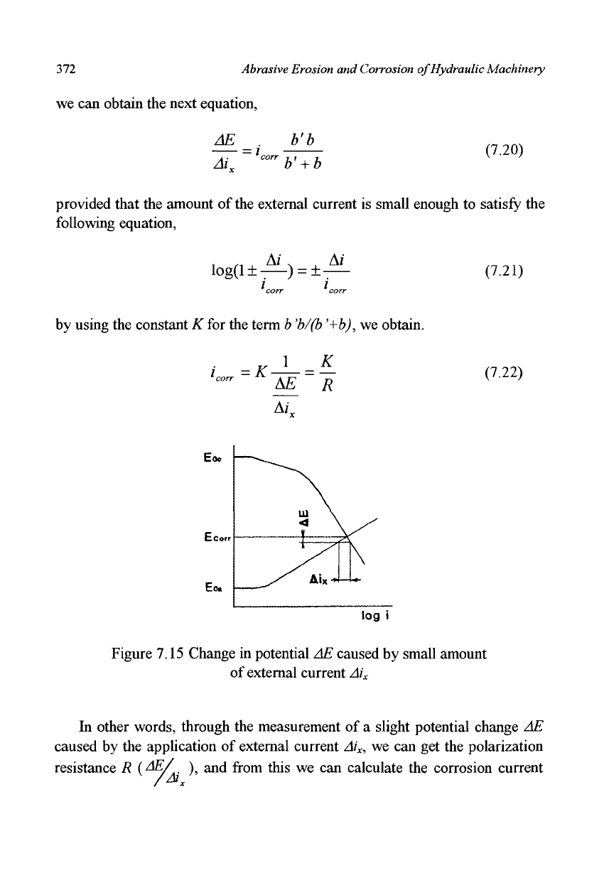
The polarization-resistance method which was developed by Stern and Geary
in 1957 is used to monitor corrosion rate by means of the polarization curve.
The state of a test specimen in corrosion is expressed with E
corr
, and
i
corr
in
Figure 7.15, which is the intersection of two inner polarization curves. If a
very weak external current Ai
x
is supplied along with an arrangement similar
to that shown in Figure 7.11, the potential of the test specimen changes
slightly by the amount AE. Because these polarization curves can be
expressed as in equations (7.12) and (7.13), and because the external current,
the increments in anodic current as well as that in cathodic current can all be
related in the following equation,
M
x
= Ai
c
+
M
a
(7.19)
372 Abrasive Erosion and Corrosion of Hydraulic Machinery
we can obtain the next equation,
AE _. b'b
Ai„ ~
horr
b'
+
b
(7.20)
provided that the amount of
the
external current is small enough to satisfy the
following equation,
log(l±-—)
=
±-—
corr corr
by using the constant K for the term b
*b/(b
'+b), we obtain.
AT
(7.21)
(7.22)
Eo.
log i
Figure 7.15 Change in potential AE caused by small amount
of external current Ai
x
In other words, through the measurement of a slight potential change AE
caused by the application of external current Ai
x
, we can get the polarization
resistance R {^/
A
), and from this we can calculate the corrosion current
Corrosion on Hydraulic Machinery 373
i
CO
or.
This method enables us to measure the corrosion rate electrically in a
short time. This is now an indispensable procedure for monitoring corrosion.
Many factors influence the polarization curves, so that a considerable error
remains in this method. But many recent improvements have increased the
accuracy to the point where we are now quite confident of this method (See
Katoh et. al., 1985, Haruyama et. al., 1978).
7.3 Corrosion of Pump Parts
Among the various different types of pumps in use for different purposes,
seawater pumps are mostly of conventional type and are apt to suffer
corrosion damage. The quality of the material used for seawater pumps has
been improved over the years. Recently the large-sized pumps, of which the
total weight can attain 10 tons, have been made of austenitic ductile cast iron
consisting of
20%
Ni and 2% Cr (ASTM A 439 Type D2) or of cast stainless
steel consisting of 20% Cr, 29% Ni, 2.5% Cu (JIS SCS 23) and so on.
Adoption of such materials is considerably effective in reducing corrosion
damage, but corrosion problems cannot be completely overcome even though
higher-grade materials may be used. It is, therefore, desirable from an
economic point of view to use common materials such as plain cast iron,
carbon steel or type 316 stainless steel in skillful combination in order to deal
with the problem of corrosion. Dr. Kitashima and his collaborators reported
in 1986 the following examples of corrosion damage in seawater pumps and
suggested methods to prevent it, in accordance with the above-mentioned
concept. They are expert corrosion engineers who have engaged themselves in
manufacturing of various kinds of pumps for a long time in one of the largest
factories in Japan.
7.3.1 Corrosion Caused by Velocity Difference
In almost every pump, the velocity of fluid flow is different from place to
place on the surface of the pump parts, which often brings about macroscopic
corrosion cells which promote corrosion. Figure 7.16 shows the damage from
this type of corrosion on the casing surface of a seawater pump made of cast
iron. The corrosion rate of cast iron in seawater at rest is usually about 0.2
mm/year and is increased with the increase in flow velocity. On the casing
