Desurvire E. Classical and Quantum Information Theory: An Introduction for the Telecom Scientist
Подождите немного. Документ загружается.


24.1 Quantum repetition code 497
that there is more than one error in a single four-bit block is
p
(4)
= C
2
4
p
2
(1 − p)
2
+ C
3
4
p
3
(1 − p) + C
4
4
p
4
(1 − p)
0
= 6p
2
(1 − p)
2
+ 4 p
3
(1 − p) + p
4
≡ 4p
3
+ 6 p
2
− 9 p
4
.
(24.1)
It is easily checked that p
(4)
< p for p < 0.155, and p
(4)
≤ p/10 for p ≤ 0.0165, hence,
this repetition code is reliable (i.e., errors can be reliably corrected) provided p is chosen
to be sufficiently small.
Here, we shall apply the principle of repetition codes to quantum channels, which
defines the new notion of quantum error-correction coding (QECC). We may conceptu-
ally expand our view of a “quantum channel” beyond that of a quantum communication
system and conceive that it may also correspond to that of a quantum memory. Whether
information is transmitted or stored, the principle remains the same: an originator must
encode the information and input the result into a physical system, and a recipient
must do the reverse operation. We may, thus, equivalently refer to either transmission
or storage “fidelity” to qualify the quantum channel or system into or through which
information is being passed. Such a notion will be developed later.
As an example of a noisy quantum system, consider the bit-flip channel described
in Chapter 23. To recall, the bit-flip channel converts the qubits |0 and |1 into each
other with probability p. Hence, the original qubit |q=α|0+β|1 has probability
p of being transformed by the quantum channel into |q=α|1+β|0. Based on the
principle of the four-bit repetition code, it is then sensible to encode the input qubit |q
into
|
ˆ
q=α|0000+β|1111, (24.2)
for instance (we could have chosen a 3-qubit repetition code as well). This is equivalent
to encoding the basis states |0, |1 in the form
|0→|
ˆ
0=|0000
|1→|
ˆ
1=|1111,
(24.3)
where |
ˆ
0, |
ˆ
1 have the meaning of the logical |0, |1 qubits. The quantum circuit
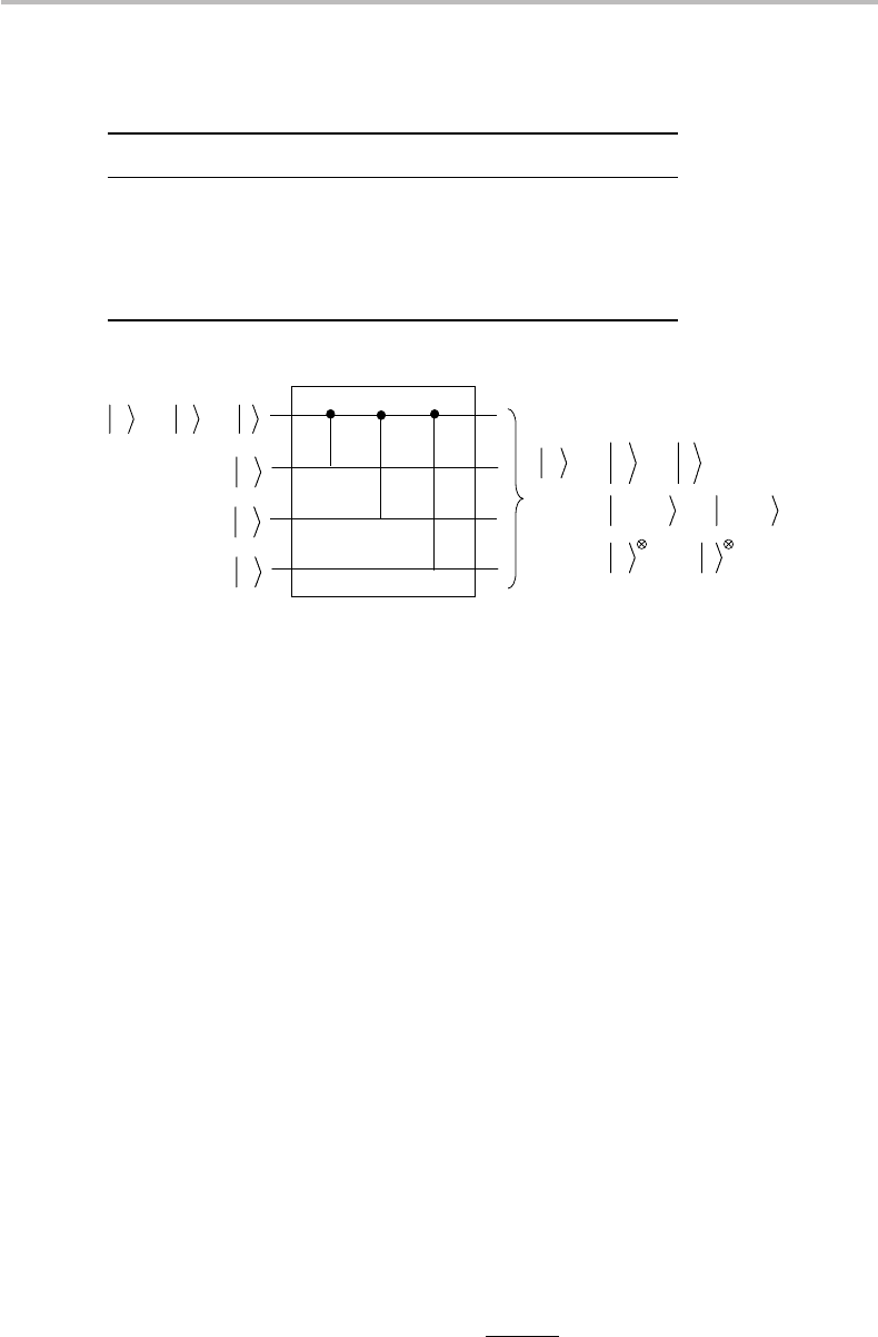
for this repetition code, which is based on three CNOT gates (see Chapter 15), is
showninFig.24.1. After passing through the bit-flip channel, the 4-qubit basis states
|0000, |1111might have experienced zero, one, two, three, or four qubit flips or errors.
We consider here the first two possibilities, whose detailed outcomes are summarized in
Table 24.1. From the recipient’s end, the detection and correction of errors is a matter of
syndrome diagnosis. The notion of “syndrome” for linear block codes and cyclic codes
was described in Chapter 11. Here, it is similarly applied to quantum error correction.
The first step is to detect the existence of errors, namely of the occurrence of single
qubit flips in the received codeword, which is achieved by means of an error syndrome
measurement. Such a measurement consists of projecting the received codeword using
498 Quantum error correction
Table 24.1 Outcome possibilities for the basis states |0000, |1111 on
passing through a bit-flip channel, assuming up to one flip.
Input Output Event
|0000, |1111|0000, |1111 No bit flip
|1000, |0111 Bit flip on 1st qubit
|0100, |1011 Bit flip on 2nd qubit
|0010, |1101 Bit flip on 3rd qubit
|0001, |1110 Bit flip on 4th qubit
10
βα
+=
q
x
0
x
x
44
10
11110000
1
ˆ
0
ˆ
ˆ
+=
+=
+=
βα
βα
βα
q
0
0
Figure 24.1 Quantum circuit for encoding a qubit |q into a 4-qubit repetition codeword |
ˆ
q
before transmission to a bit-flip channel.
the following projector set:
P
0
=
|
0000
0000
|
+|1111
1111
|
P
1
=
|
1000
1000
|
+
|
0111
0111
|
P
2
=
|
0100
0100
|
+
|
1011
1011
|
P
3
=
|
0010
0010
|
+
|
1101
1101
|
P
4
=
|
0001
0001
|
+
|
1110
1110
|
.
(24.4)
Assume that the received qubit is |
ˆ
q
=α|0010+β|1101. It is clear that a pro-
jection measurement through P
3
yields the certain outcome, or “expectation value”
P
3
=
ˆ
q
|P
3
|
ˆ
q
=1, with the post-measurement state being |
ˆ
q
∗
. We note that the
measurement does not yield any information about the amplitudes α, β, thus, leaving
the codeword unknown. Yet the measurement tells which type of error is to be corrected,
and the original codeword can be restored to its full integrity by flipping again the errored
qubit i should any P
i=1,2,3,4
measurement yield
ˆ
q
|P
i
|
ˆ
q
=1, while the measurement
ˆ
q
|P
0
|
ˆ
q
=1 indicates with certainty that there are no errors.
The effectiveness of a quantum error-correction code can be qualified through fidelity,
a notion which was introduced in Chapter 22. Assuming a noisy channel ε with the
encoded originator message ρ =|
ˆ
q
ˆ
q|and the recipient message ε(ρ) = ρ
, the fidelity
can be defined as follows:
F =
ˆ
q|ρ
|
ˆ
q. (24.5)

24.1 Quantum repetition code 499
In the case of the bit-flip channel, we have (Eq. (23.11)):
ρ
= ε(ρ)
= pXρ X + (1 − p)ρ
= pX|
ˆ
q
ˆ
q|X + (1 − p)|
ˆ
q
ˆ
q|.
(24.6)
From the definition in Eq. (24.5), the corresponding fidelity of the code is
F =
ˆ
q|ρ
|
ˆ
q
=
ˆ
q|pX|
ˆ
q
ˆ
q|X |
ˆ
q+(1 − p)
ˆ
q|
ˆ
q
ˆ
q|
ˆ
q
≡
(
p
|
ˆ
q|X |
ˆ
q
|
2
+ (1 − p).
(24.7)
Consider now some cases of interest. If we use no error correction, the two basic sets
of pure-state symbols we can use are |q=|0, |1 and |q=|+, |−. As we know,
the action of the Pauli matrix X is to flip the states |0, |1 or X|0=|1 and X|1=
|0, yielding q|X |q=0 and F =
√
1 − p in the first case. The fidelity, thus, ranges
from F = 1 (noiseless channel, p = 0) to F = 0 (“certain” bit-flip channel, p = 1).
In the second case, the action of X leaves the states |+, |− invariant, i.e., X|+ =
(X |0+X |1)/
√
2 = (|1+|0)/
√
2 ≡|+and X |− = (X |0−X|1)/
√
2 = (|1−
|0)/
√
2= e
iπ
|− ≡ |−, which yields |q|X|q| = 1 and, hence, F = 1. The fidelity
is, thus, maximal, even if the channel is “noisy” and no error-correction coding is
implemented! Consider, next, the case with the error-correction code implementation
according to Eq. (24.2), i.e., |
ˆ
q=α|
ˆ
0+β|
ˆ
1, with ρ =|
ˆ
q
ˆ
q|. We now have a noisy
quantum channel that has the capability of corrupting one, two, or more qubits, which
calls for a definition of ε(ρ) that is, in fact, different from Eq. (24.6). For each corruption
pattern x, we need to introduce the corresponding quantum operation ε
x
(ρ). Here are
the different corruption patterns with their operations:
No error: ε
0
(ρ) = (1 − p)
4
I
⊗4
ρ I
⊗4
, (24.8)
Exactly one error: ε
a
(ρ) = p(1 − p)
3
X ⊗ I
⊗3
ρ X ⊗ I
⊗3
+ I ⊗ X ⊗ I
⊗2
ρ I ⊗ X ⊗ I
⊗2
+ I
⊗2
⊗ X ⊗ Iρ I
⊗2
⊗ X ⊗ I
+ I
⊗3
⊗ Xρ I
⊗3
⊗ X
, (24.9)
Exactly two errors: ε
b
(ρ) = p
2
(1 − p)
2
X
⊗2
⊗ I
⊗2
ρ X
⊗2
⊗ I
⊗2
+ X ⊗ I ⊗ X ⊗ Iρ X ⊗ I ⊗ X ⊗ I
+ X ⊗ I
⊗2
⊗ Xρ X ⊗ I
⊗2
⊗ X
+ I ⊗ X
⊗2
⊗ Iρ I ⊗ X
⊗2
⊗ I
+ I ⊗ X ⊗ I ⊗ Xρ I ⊗ X ⊗ I ⊗ X
+ I
⊗2
⊗ X
⊗2
ρ I
⊗2
⊗ X
⊗2
,
(24.10)
Exactly three errors: ε
c
(ρ) = p
3
(1 − p)
X
⊗3
⊗ Iρ X
⊗3
⊗ I
+ X
⊗2
⊗ I ⊗ Xρ X
⊗2
⊗ I ⊗ X
+ X ⊗ I ⊗ X
⊗2
ρ X ⊗ I ⊗ X
⊗2
+ I ⊗ X
⊗3
ρ I ⊗ X
⊗3
,
(24.11)
Exactly four errors: ε
d
(ρ) = p
4
X
⊗4
ρ X
⊗4
, (24.12)

500 Quantum error correction
which makes up the overall channel definition
ρ
= ε(ρ) = ε
0
(ρ) +ε
a
(ρ) +ε
b
(ρ) +ε
c
(ρ) +ε
d
(ρ). (24.13)
Here, there is no point in developing the full expression of the recipient’s qubit by
substituting ρ =|
ˆ
q
ˆ
q|=(α|
ˆ
0+β|
ˆ
1)( ¯α
ˆ
0|+
¯
β
ˆ
1|), which generates no less than 4 ×
16 = 64 operator terms! Rather, it is sensible to conclude directly that after error-
correction decoding, which would ideally detect and correct all possible error patterns,
the transmitted qubit state takes the form:
(
ρ
)
∗
= ε
∗
(ρ)
= [
(
1 − p
)
4
+ 4 p
(
1 − p
)
3
+ 6 p
2
(
1 − p
)
2
+ 4 p
3
(
1 − p
)
+ p
4
]|
ˆ
q
ˆ
q|
≡|
ˆ
q
ˆ
q|.
(24.14)
If the QECC only has the capability of correcting up to a single error (using the projectors
P
i=1,2,3,4
), we may write
ε
∗
(ρ) = [
(
1 − p
)
4
+ 4 p
(
1 − p
)
3
+ ...]|
ˆ
q
ˆ
q|, (24.15)
with the missing terms corresponding to patterns of more than one error (see further
in discussion about correcting higher-order error patterns). In this case, the fidelity is
given by
F(p) =
ˆ
q|ε
∗
(ρ)|
ˆ
q
≡
(
(
1 − p
)
4
+ 4 p
(
1 − p
)
3
+ ... ≥
(
(
1 − p
)
4
+ 4 p
(
1 − p
)
3
= F
min
.
(24.16)
In the above, F
min
represents a lower bound for the fidelity corresponding to an error-
correction capability of up to one qubit. We may compare the minimum fidelity F
min
to
that corresponding to the transmission of |0, |1 without error-correction coding, and
for which F =
√
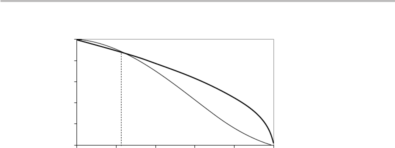
1 − p, as established earlier. It is found numerically that F
min
> F
under the condition p < p
max
= 0.23, as illustrated in Fig. 24.2. This result means that
for channels with p ≥ 0.23, there is no point or merit whatsoever in implementing this
quantum repetition code! In comparison, the 3-qubit repetition code yields a minimum
fidelity of F
min
=
(1 − p)
3
+ 3 p(1 − p)
2
(which is straightforward to establish), to
which the condition p < 0.5 = p
max
corresponds. The fact that the channel bit-flip prob-
ability p may not exceed some threshold value p
max
, and that this threshold decreases as
we may increase the number of repeated qubits, nicely illustrates the intrinsic limitations
of the quantum repetition code.
As we have seen from the above description, implementing the repetition code with
longer codewords increases the chance of obtaining more than one (bit-flip) error.
How about the possibility of correcting these higher-order error patterns? We may
easily convince ourselves that, unfortunately, the repetition code does not offer such a
possibility. Indeed, consider, for instance, the projection operator P =|00110011|+
|11001100|. Using such a projection will tell with certainty that there are two errors.
But there is no way of telling whether these errors occurred on the first two or the last two
24.1 Quantum repetition code 501
0
0.2
0.4
0.6
0.8
1
0 0.2 0.4 0.6 0.8 1
Probability
p
Fidelity
min
F
F
max
p
Figure 24.2 Fidelity of 4-qubit repetition coding in bit-flip channel for no error correction (F),
and up to one error correction (F
min
), showing improvement in the region p < p
max
= 0.23.
qubits, these two events being equiprobable. The same ambiguity prevails with the two
other possible projectors, P =|01010101|+|10101010| and P =|01100110|+
|10011001|. The detection of three errors would take the same projectors as P
i=1,2,3,4
defined in Eq. (24.4), but this time with an ambiguity in favor of a single-error event. This
shows that the quantum repetition code is inadequate for higher-order error detection
and correction.
How about implementing the quantum repetition code in the phase-flip channel?In
Chapter 11, we saw that the phase-flip channel transforms a qubit |q=α|1+β|0
into |q=α|1−β|0, or introduces a dephasing factor e
iπ
between the two complex
amplitudes α, β. Clearly, the effect of this channel is to flip the states |+ and |− into
each other. Therefore, we can apply the same repetition-code principle as described
previously, using, this time (and for instance), the 4-qubit encoding scheme:
|+ →
+
+
ˆ
+
=
=
|
++++
|− →
+
+
ˆ
−
=
=
|
−−−−
,
(24.17)
where |
ˆ
+, |
ˆ
−have the meaning of the logical |+, |−qubits. In the basis representation
{|+, |−}, there is strictly no difference between this quantum repetition code and that
applying to the bit-flip channel in the basis representation {|0, |1}.Butwemayusethe
code in Eq. (24.17) in the latter basis by means of Hadamard gates. As we have seen in
Chapter 15, the Hadamard gate H performs the following transformations:
H|0=|+
H|1=|−
H|+ = |0
H|− = |1.
(24.18)
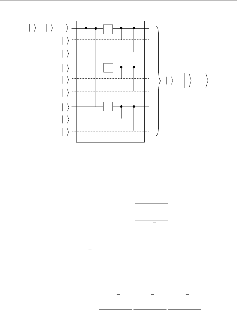
The encoding circuit for this repetition code is similar to the one concerning the bit-flip
channel (Fig. 24.1) with the inclusion of three Hadamard gates to effect this conversion,
as shown in Fig. 24.3. The originator qubit |q=α|1+β|0 is, thus, transformed into
|q=α|
ˆ
+ + β|
ˆ
−.

502 Quantum error correction
10
βα
+=
q
x
0
x
x
44
ˆ
ˆ
ˆ
−++=
−++=
βα
βα
q
0
0
H
H
H
H
Figure 24.3 Quantum circuit for encoding a qubit |q into a 4-qubit repetition codeword |
ˆ
q
before transmission to a phase-flip channel.
The error syndrome measurement can be performed with the same projector set
P
i=1,2,3,4
as defined in Eq. (24.4), but with the 1, 0 symbols inside the bra–kets
·
|
/
|
·
being switched into +, −, namely, P
0
=|++++++++|+|−−−−−−−−|,
and so on. Another possibility is to pass each of the received codeword qubits through
a Hadamard gate, corresponding to the operation H
⊗4
ε(|
ˆ
q
ˆ
q|), which allows one to
perform the error syndrome measurement through the same projector set P
i=1,2,3,4
as in
the bit-flip channel. Clearly, the fidelity characteristics and limitations of the quantum
repetition code for the phase-flip channel are strictly the same as in the case of the bit-flip
channel.
I shall conclude this section by showing an important property, according to which the
projector set P
i=1,2,3,4
is not the only tool to perform error syndrome measurements in bit-
or phase-flip channels. This will be very useful in the next section, concerning the Shor
code. Consider indeed that we have the possibility of performing partial measurements
with the aim of comparing qubit pairs. For instance, we may compare the first and the
second qubit, or the second and the third, or the first and the third, and so on. Should
any comparison reveal a difference, then an error is detected. One must then perform as
many such comparisons as necessary to obtain an unambiguous error syndrome, leading
to certain error correction. Let us see how this approach can be implemented. With
a 3-qubit bit-flip code, comparing qubit pairs consists of projecting the received state
ˆσ = ε(|
ˆ
q
ˆ
q|) by using the following “observable” operators:
Z
12
= (|0000|+|1111|) ⊗ I − (|0101|+|1010|) ⊗ I
Z
23
= I ⊗
(
|0000|+|1111|
)
− I ⊗
(
|0101|+|1010|
)
Z
13
=|00|⊗I ⊗|00|+|11|⊗I ⊗|11|
−
(
|00|⊗I ⊗|11|+|11|⊗I ⊗|00|
)
.
(24.19)
It is clear that the expectation value Z
ij
=
ˆ
q|Z
ij
|
ˆ
qfor any of the above three operators
Z
ij
is equal to +1, should the qubits i and j match (no error), while it is equal to −1,
should they not match (error). Let us leave here the consideration of being capable of
physically measuring observables, such as ±1. The matter is simply that the partial
measurement yields two possible logical answers: error or no error on the pair of qubits
considered, corresponding to classical YES or NO information. Such information is the
key to the elaboration of an error diagnostic, leading to corrective action. Since a single
measurement (or YES or NO information) is not sufficient to tell which of the two qubits

24.2 Shor code 503
is actually errored (or flipped), we may perform as many successive measurements as
required to reach an unambiguous error diagnostic. The nice feature of the approach is
that these projective measurements do not alter the codeword, i.e., they leave it in the
same post-measurement state! In the 3-qubit coding example, let us see that it merely
suffices to perform two such measurements in a row. Indeed, assume we obtain the two
measurements Z
12
and Z
13
.IfZ
12
=Z
13
=1, there is no error and, therefore, no
action is required. If Z
12
=1 and Z
13
=−1, we have detected an error on the third
qubit and, therefore, the corrective action is to flip it. We may reach the same conclusion
for the measurement pair Z
12
, Z
23
or Z
13
, Z
23
. Thus, any arbitrary choice of only
two successive measurements of this type altogether yields 2
2
= 4 possible syndrome
diagnostics, covering all patterns from zero error to one single error concerning any of
the three qubits. The result is the same as using the measurement set P
i=1,2,3,4
, except
that only two projection operators instead of four have been used. In any case, it is
important to recall that the output codeword |q
and the post-measurement states P
i
|q
or Z
ij
|q
are identical.
It is now only a straightforward technical matter to describe how the Z
ij
projectors
defined in Eq. (24.19) can be realized. We recall from Chapter 16 the Z-gate, also
referred to as the σ
3
or σ
z
Pauli matrix, whose action is to introduce a π phase flip
between the qubit amplitudes (see Table 16.2). It is left as an easy exercise to show that
the measurement projector Z
ij
, as defined in Eq. (24.19), in fact summarizes into the
simultaneous application of Z onto the qubits i and j in the codeword to be analyzed.
Namely,
Z
12
= Z ⊗ Z ⊗ I ≡ Z
⊗2
⊗ I
Z
23
= I ⊗ Z ⊗ Z ≡ I ⊗ Z
⊗2
Z
13
= Z ⊗ I ⊗ Z .
(24.20)
We may write the above definitions in the compact form: Z
12
≡ Z
1
Z
2
I
3
≡ Z
1
Z
2
, Z
23
≡
I
1
Z
2
Z
3
≡ Z
2
Z
3
, and Z
13
≡ Z
1
I
2
Z
3
≡ Z
1
Z
3
, with the indices in the right-hand side
referring to the action of the operator onto the corresponding qubits, and with the
identity matrix applying to the remaining qubit being overlooked.
24.2 Shor code
In this section, I describe the Shor code, a QECC that concatenates the features of the
bit-flip and phase-flip repetition codes, as implemented with 9-qubit codewords. The
nice feature of the Shor code is that it can correct any single bit-flip or phase-flip error,
and as a matter of fact, any error, as will be established. The encoding principle proceeds
as follows. First, consider the 3-qubit phase-flip repetition code. The quantum circuit is
the same as shown in Fig. 24.3, with the last wire removed. As we have seen earlier, this
code performs the following transformation:
|0→|
ˆ
0=
|
+++
|1→|
ˆ
1=
|
−−−
.
(24.21)
504 Quantum error correction
10
βα
+=
q
x
0
x
1
ˆ
ˆ
0
ˆ
ˆ
ˆ
βα
+=
q
0
0
0
x
x
0
0
x
x
0
0
x
x
H
H
H
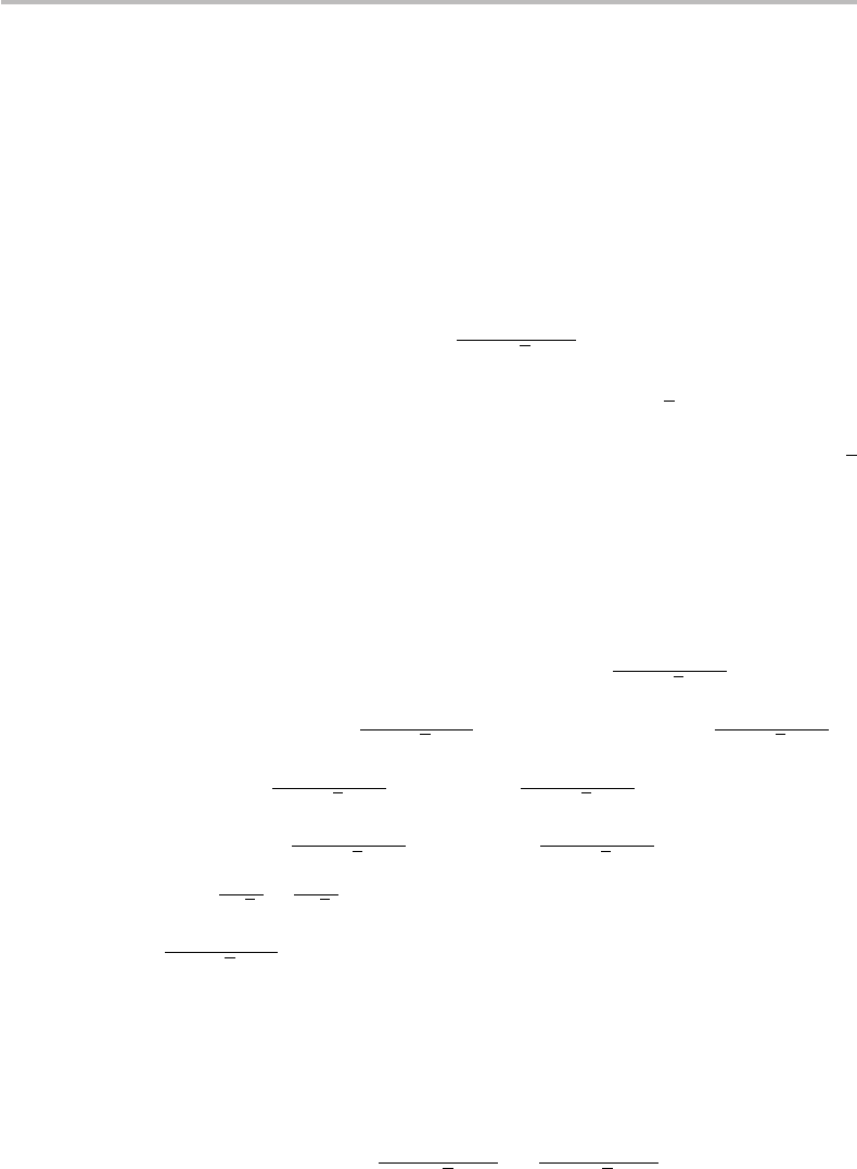
Figure 24.4 Quantum circuit for encoding a qubit |q into a 9-qubit repetition codeword |
ˆ
ˆ
q
before transmission to a bit-phase-flip channel.
In a second stage, we consider the 3-qubit bit-flip repetition code. The quantum circuit
is the same as shown in Fig. 24.1, with the last wire removed. Clearly, such a circuit
encodes the qubits |+ = (|0+|1)/
√
2 and |+ = (|0−|1)/
√
2 according to
|+ → |
ˆ
+ =
|
000
+
|
111
√
2
|− → |
ˆ
− =
|
000
−
|
111
√
2
.
(24.22)
We notice from the above definition that the two qubits |
ˆ
+, |
ˆ
− are entangled.They
represent the 3-qubit extension of the EPR or Bell states
|
β
00
=
(
|00+|11
)
/
√
2 and
|
β
10
=
(
|00−|11
)
/
√
2, which were described in Chapter 18. Such a property will be
used later, when considering error correction. The end result of applying successively,
or concatenating the two encoding phases, as defined in Eqs. (24.19) and (24.20), is the
following:
|0→
+
+
+
ˆ
ˆ
0
/
=
|
000
+
|
111
√
2
|
000
+
|
111
√
2
|
000
+
|
111
√
2
|1→
+
+
+
ˆ
ˆ
1
/
=
|
000
−
|
111
√
2
|
000
−
|
111
√
2
|
000
−
|
111
√
2
.
(24.23)
The corresponding encoding circuit is shown in Fig. 24.4. The first stage of the circuit,
which includes two CNOT and three H gates, performs the phase-flip repetition coding
as defined in Eq. (24.19). The second stage, which includes six CNOT gates, performs
the bit-flip repetition coding as defined in Eq. (24.20). For clarity, the ancillary qubits
used for the second stage are shown with dashed lines.

24.2 Shor code 505
Table 24.2 Corrective actions in Shor code from phase-flip syn-
drome diagnostic based on measurements of
(
X
123456
, X
456789
)
and the principle of majority logic.
X
123456
AB
X
456789
BC
Corrective action
1 1 None
1 −1 Flip phase in block C
−1 1 Flip phase in block A
−1 −1 Flip phase in block B
In the Shor code, syndrome diagnosis and error correction works in a way conceptually
similar to that in the bit-flip and phase-flip repetition codes described in the previous
section, except that here we want to identify and correct both types of error.Thetask
appears a bit tedious because the codewords are made of the 9-qubit states, |
ˆ
ˆ
0 and |
ˆ
ˆ
1,
defined in Eq. (24.23). I shall first consider the occurrences of phase-flip and bit-flip
separately, and eventually show that both types of event can be corrected.
Phase-flip error
For instance, calling the three 3-qubit blocks A, B, C, if a single phase-flip occurs on
any qubit within block A, the channel outputs:
|
ˆ
ˆ
0→|
ˆ
ˆ
0
=
|000−|111
√
2
+
+
+
+
A
|000+|111
√
2
+
+
+
+
B
|000+|111
√
2
+
+
+
+
C
|
ˆ
ˆ
1→|
ˆ
ˆ
1
=
|000+|111
√
2
+
+
+
+
A
|000−|111
√
2
+
+
+
+
B
|000−|111
√
2
+
+
+
+
C
.
(24.24)
The first step in the syndrome diagnosis consists of comparing the relative phase of
blocks A, B then of blocks B, C (or any other two pair selection), just like in the
1-qubit phase-flip channel case described earlier. Majority logic then dictates which
block may have been corrupted and where the phase correction applies. It is left as an
(easy) exercise to show that comparing the signs of A, B blocks can be performed by
measuring X
123456
= X
1
X
2
X
3
X
4
X
5
X
6
, and likewise for the B, C blocks with X
456789
=
X
4
X
5
X
6
X
7
X
8
X
9
, where X
i
is the Pauli matrix X applied to the qubit i. The entire
syndrome diagnostic, leading to the proper corrective action on the concerned block
phase, thus, consists of performing the two measurements
(
X
123456
, X
456789
)
, while the
other possibility is
(
X
123456
, X
123789
)
, both being applicable in any measurement order.
Table 24.2 summarizes the corrective actions from the syndrome diagnostic based on
(
X
123456
, X
456789
)
.
To restore the phase in the corrupted block, say, for instance, A, the corrective action
is to apply the operator Z
1
Z
2
Z
3
. Indeed, because of the properties Z |0=|0 and
Z|1=−|1, the phase of the 3-qubit block A is flipped according to
Z
1
Z
2
Z
3
(
|000−|111
)
=|000−(−1)
3
|111
≡|000+|111.
(24.25)
506 Quantum error correction
Bit-flip error
The syndrome diagnosis for bit-flip errors is basically the same as described in the earlier
section. As in the phase-flip case, the diagnosis may proceed by blocks, considering
successively the blocks A, B, C. As we have seen, the procedure consists of comparing
qubit pairs i, j and j, k by means of Z
ij
= Z
i
Z
j
and Z
jk
= Z
j
Z
k
measurements.
Considering any block U = A, B, C, assume for instance a bit-flip error happening on
the second qubit of |
ˆ
ˆ
0
U
, such that the channel outputs:
+
+
+
ˆ
ˆ
0
/
U
=
|
010
+
|
101
√
2
. (24.26)
We ought to notice that a single bit-flip error in
(
|000+|111
)
/
√
2 corrupts not only one
but both qubit terms in the sum, because the state is entangled, as we have mentioned ear-
lier. Thus, there is no possibility to have an error pattern of the type
(
|
010
+|111
)
/
√
2
where the second term would remain uncorrupted. This is a nice feature of the Shor
code, which is going to be exploited in the syndrome diagnostic. To show this, we first
apply Z
12
on block U to obtain:
Z
12
+
+
+
ˆ
ˆ
0
/
U
=
[
(
|0000|+|1111|
)
⊗ I −
(
|0101|+|1010|
)
⊗ I
]
|
010
+
|
101
√
2
=
(
|0000|+|1111|
)
⊗ I
|
010
+
|
101
√
2
−
(
|0101|+|1010|
)
⊗ I
|
010
+
|
101
√
2
=
|0000|⊗I
|
010
+
|
101
√
2
+|1111|⊗I
|
010
+
|
101
√
2
−|0101|⊗I
|
010
+
|
101
√
2
−|1010|⊗I
|
010
+
|
101
√
2
= 0 +0 −
|
010
√
2
−
|
101
√
2
≡−
|
010
+
|
101
√
2
.
(24.27)
Hence, the measurement
Z
12
U
=
.
ˆ
ˆ
0
+
+
+
Z
12
+
+
+
ˆ
ˆ
0
/
U
=
010|+101|
√
2
−
|010+|101
√
2
≡−1.
(24.28)
We notice here that the post-measurement state is the same as the measured state
|
ˆ
ˆ
0
, within an unobservable phase factor e
iπ
. Hence, the possibility of continuing the
