Dake L.P. Fundamentals of reservoir engineering
Подождите немного. Документ загружается.


REAL GAS FLOW: GAS WELL TESTING 281
The theoretical equation describing the pseudo pressure drop during the second flow
period can be derived from the basic test equation (8.39) as
1max max
iwf1DDDDDDD
2DD 22
kh
(m(p ) m(p )) Q (m (t t t ) m ( t t ))
1422T
Qm(t)QS
′′
−= +∆+−∆+
′′
++
(8.58)
where
t
′
is the time measured from the start of the second flow period at rate Q
2
,
(fig. 8.14). This equation is analysed for transient conditions during the second flow
period, that is, for small values of t´. In this case the expression
1max max
1DD D D DD D
Q (m(t t t) m( t t))
′′
+∆ + − ∆ +
in equ. (8.58) can be regarded as being constant. If both t
1
and ∆t
max
are short so that
both the m
D
functions can be evaluated under transient conditions the above statement
is quite correct and, in fact, the difference between the m
D
functions is both small and
constant. For a very long initial flow period, corresponding to a routine well survey
rather than an initial test, the difference between the m
D
functions can only be regarded
as constant on the grounds that t is small, which is always the case since the wellbore
pressure response at rate Q
2
is only being analysed during the brief, initial, transient
flow period. Therefore, equ. (8.58) implies that a plot of m(p
wf
) versus log t will be
linear, for transient flow, with slope
2
1637Q T
m
kh
=
which leads to a re-determination of k. The skin factor can be evaluated by expressing
equ. (8.58) as
iwf iws2DD22
kh kh
(m(p ) m(p )) (m(p ) m(p )) Q m (t ) Q S
1422T 1422T
′′′
−= −+ +
(8.59)
in which
ws
p
′
is the hypothetical static pressure that would be obtained had the buildup
been continued for a time ∆t
max
+ t
′
. The value of
ws
p
′
will therefore increase as t´
increases. Equation (8.59) can then be solved to give
2
S
′
as
ws 1 hr wf 1 hr
22
2
iw
(m(p ) m(p )
k
S S DQ 1.151 log 3.23
m(c)r
φµ
−−
′
æö
−
′
=+ = − +
ç÷
èø
(8.60)
in which both
()
wf
mp and
()
ws
mp
′
are evaluated for t
′
= 1 hour. The latter can be
obtained by extrapolation of the final buildup trend for one hour after the buildup has
ceased. However, this correction is seldom applied and usually
()
ws
1hr
mp
−
′
is set equal
to
()
ws
mp , evaluated for the final closed in pressure.
The following exercise illustrates the method of buildup analysis for a well test in a new
reservoir in which p
i
is the initial reservoir pressure.

REAL GAS FLOW: GAS WELL TESTING 282
EXERCISE 8.3 PRESSURE BUILDUP ANALYSIS
Instead of applying a multi-rate flow test, the reservoir described in exercise 8.2 is
tested by producing it for 3 hours at a rate of 40 MMscf/d, closing in for an 8 hour
buildup and finally, by producing for a further 3 hours at a rate of 60 MMscf/d. The
pressures recorded during the flowing and closed in periods are listed in table 8.10 and
8.11, respectively.
First Flow Period
Q
1
= 40 MMscf/d
Second Flow Period
Q
2
= 60 MMscf/d
Flowing time
hrs
p
wf
psia
m (p
wf
)
psia
2
/cp
p
wf
psia
m (p
wf
)
psia
2
/cp
.75 3602 830.45 × 10
6
3076 648.61 × 10
6
1.00 3596 828.38 " 3066 645.16 "
1.25 3591 826.65 " 3059 642.74 "
1.50 3587 825.27 " 3053 640.66 "
1.75 3583 823.88 " 3048 638.93 "
2.00 3580 822.85 " 3043 637.21 "
2.25 3577 821.81 " 3038 635.48 "
2.50 3575 821.12 " 3036 634.79 "
3.00 3570 819.39 " 3029 632.37 "
TABLE 8.10
Closed in time
∆t hrs
p
ws
psia
m(p
ws
)
psia
2
/cp
Closed in time
∆t hrs
p
ws
psia
m(p
ws
)
psia
2
/cp
.5 4100 1002.61×10
6
3.5 4272 1062.07×10
6
1.0 4255 1056.19 " 4.0 4274 1062.76 "
1.5 4263 1058.96 " 5.0 4276 1063.45 "
2.0 4267 1060.34 " 6.0 4277 1063.80 "
2.5 4269 1061.03 " 7.0 4278 1064.14 "
3.0 4271 1061.72 " 8.0 4279 1064.49 "
TABLE 8.11
Since the fluid properties are the same as in the two previous exercises, equ. (8.48)
can be used as the relationship between real and pseudo pressures. All other data
presented in exercise 8.2 can be used in the current exercise.
1) From the pressure buildup determine p
i
, k and
1
S
′
.

REAL GAS FLOW: GAS WELL TESTING 283
2) From the flow tests determine k,
1
S
′
,
2
S
′
and hence D, or F.
EXERCISE 8.3 SOLUTION
1) Buildup Analysis
For a flowing time of 3 hours, the data necessary to draw the Horner buildup plot are
listed in table 8.12.
∆t
hrs
1
tt
log
t
+∆
∆
m(p
ws
)
psia
2
/cp
∆t
hrs
1
tt
log
t
+∆
∆
m(p
ws
)
psia
2
/cp
.5 .845 1002.61×10
6
3.5 .269 1062.07×10
6
1.0 .602 1056.19 " 4.0 .243 1062.76 "
1.5 .477 1058.96 " 5.0 .204 1063.45 "
2.0 .398 1060.34 " 6.0 .176 1063.80 "
2.5 .342 1061.03 " 7.0 .155 1064.14 "
3.0 .301 1061.72 " 8.0 .138 1064.49 "
(9.0) (.125) (1064.65) "
TABLE 8.12
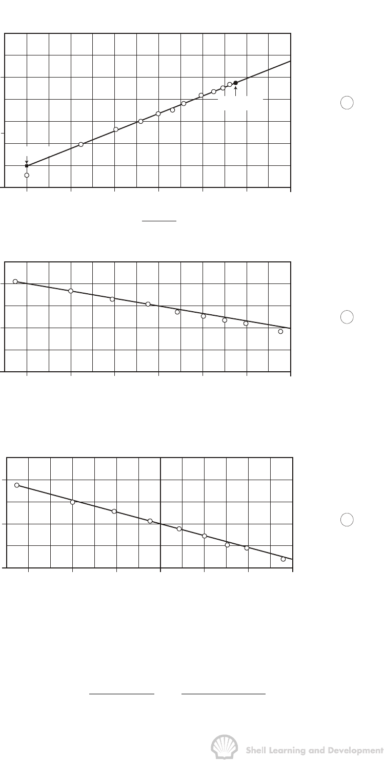
The corresponding buildup plot is shown as fig. 8.15 (a), from which the slope has
been determined as
62
1
1637Q T
m 16.17 10 psia / cp / log cycle
kh
=× =
which for a fully penetrating well gives
3
6
1637 40 10 660
k53.5mD
16.17 10 50
×× ×
==
××
and the extrapolation to ∆t = ∞ gives
m(p
i
) = 1066.7 × 10
6
psia
2
/cp
p
i
= 4285 psi
The value of
()
ws
1hr
mp
−
′
taken from the extrapolated linear trend is 1057 ×10
6
psia
2
/cp
and therefore, using equ. (8.55)

REAL GAS FLOW: GAS WELL TESTING 284
1065
1060
1055
830
820
810
650
640
630
-.1
0
.1 .2
.3
.4
.5
log t
-.1
0
.1 .2
.3
.4
.5
log t
65
4
3
21
0
log
t + t
t
∆
∆
m(p )
(psia /cp) 10
ws
26
m(p )
(psia /cp) 10
wf
26
m(p )
(psia /cp) 10
wf
26
m(p )
ws 1 - hr
m(p )
’
ws 1 - hr
m(p*) =
1066.7
a
b
c
×
×
×
Fig. 8.15 Complete analysis of a pressure buildup test in a gas well: (a) buildup
analysis (table 8.12); (b) and (c) transient flow analyses of the first and
second flow periods, respectively (table 8.10)
6
11
1057 819.4 53.5 10
S S DQ 1.151 log 3.23 10.22
16.17 .15 3.6 .09
æö
−×
′
=+ = − + =
ç÷
××
èø

REAL GAS FLOW: GAS WELL TESTING 285
2) Flow Analysis
Plots of m(p
wf
) versus log t for the data listed in table 8.10, are shown as fig. 8.15 (b)
and (c), from which the data presented in table 8.13 have been determined.
Rate
Mscf/d
Slope
psia
2
/cp/log cycle
m(p
wf
)
1-hr
k
mD
Total Skin
40×10
3
16.64×10
6
828.38×10
6
45 9.9
60 " 26.08 " 645.16 " 43 11.9
TABLE 8.13
The values of the permeability in this table have been calculated using equ. (8.54) for
rates Q
1
and Q
2
and the total skin factors using equs. (8.57) and (8.60) for the first and
second flow periods respectively. In applying equ. (8.60) the value of
()
ws
1hr
mp
−
′
has
been determined from the buildup plot for ∆t = 9 hours as 1064.65 × 10
6
psia
2
/cp
(fig. 8.15 (a) and table 8.12). The reader can verify that irrespective of whether
()
ws
1hr,
mp
−
′
()
ws
mp for the maximum buildup time, or m(p
i
) is used in equ. (8.60) makes
very little difference to the calculated value of
2
S
′
. Finally, S and D can be calculated by
solving the equations
1
S
′
=9.9=S + 40 × 10
3
D
2
S
′
= 11.9 = S + 60 × 10
3
D
to give S = 5.9; D = 1.0 × 10
-4
/Mscf/d
and F =
1422 DT
kh
= 0.043 psia
2
/cp/(Mscf/d)
2
and from these figures the Darcy flow coefficient B can be calculated for the estimated
values of A and C
A
, equ. (8.44), for use in long term well deliverability calculations.
A similar example of a pressure buildup analysis, for a low permeability reservoir
(k = 5 mD),has been presented in the literature by Al-Hussainy and Ramey
3
. The main
advantage of this type of test over the multi-rate drawdown test is the same as
mentioned in Chapter 7, sec. 7. It is, that the buildup analysis will provide values of
k and
1
S
′
which are independent of the value of m(t
D
) at the time of the survey.
Furthermore, since only the transient pressure response during each flow period is
interpreted, then it means that the entire test can be analysed without having to be
concerned about the size or shape of the area drained or the well position with respect
to the boundary.
The pressure buildup test can also be used for the routine surveys conducted at
regular intervals throughout the producing life of the field. Prior to the survey the well
must be produced at a constant rate for a sufficient period of time so that the flow is
under semi-steady state conditions. This renders transient analysis of the first flow
period, at rate Q
1
, impossible but analysis of the buildup will yield values of k and
1
S
′
.
Following this, k and
2
S
′
can be determined from the transient analysis of the second

REAL GAS FLOW: GAS WELL TESTING 286
flow period at rate Q
2
. The main purpose of this type of test is to determine the current
average pressure within the drainage boundary of the well, p. Theoretically, this can
be done by using either the method of Matthews, Brons and Hazebroek, or Dietz (refer
Chapter 7, sec. 7), but the difficulty is to determine at what pressure the
µ
c product
should be evaluated which is required to calculate t
DA
for use with either of these
methods. For the initial well tests described in exercises 8.1-3, the product (
µ
c)
i
evaluated at the initial equilibrium pressure could be used but for a survey made, say,
several years after the well has started to produce this can lead to serious error. The
basic problem is that for very long flowing times the calculation of m
D
using the semi-
steady state equation (8.33) with the (
µ
c)
i
product does not accurately correlate with
the similar p
D
function for liquid flow, equ. (7.27).
Kazemi
10
has presented an iterative method for determining the pressure at which,
µ
c
should be evaluated and hence the correct value ofp. The method is applicable for
wells producing under semi-steady state conditions at the time of the survey. In this
case, as shown in Chapter 7, sec. 7, the value of the flowing time used to plot the
buildup is immaterial providing that t ≥ t
SSS
, the time required for semi-steady state
conditions to be reached for the particular geometrical configuration of the drainage
area. Strictly speaking, this statement is only valid when applied to a liquid, in which
case the MBH plots, figs. 7.11-15, are linear functions of the dimensionless flowing
time t
DA
. For a real gas, however, the m
D(MBH)
functions deviate from the linear p
D(MBH)
functions for large values of t
DA
, as shown in fig. 8.16. This implies that using the MBH
charts, for a large value of the (effective) flowing time, can lead to an error in the
determination ofp in the analysis of a routine buildup survey in a gas well.
Kazemi argues, and substantiates his argument with detailed numerical simulation, that
if the buildup is plotted for a flowing time t
SSS
,where
SSS
p
SSS DA SSS
(c) A
t(t)
0.000264k
φµ
= (8.61)
and the MBH method applied for a dimensionless flowing time (t
DA
)
SSS
, then the portion
of the MBH charts for which the liquid and gas MBH functions correlate is used and this
should result in the correct determination of p. Of course, in order to calculate t
SSS
,
using equ. (8.61), requires a knowledge of p
SSS
, the average pressure at a time t
SSS
prior to the buildup and the evaluation of the
µ
c product at this pressure. A simple
iterative scheme for calculating p
SSS
, t
SSS
and hence p is shown in fig. 8.17.

REAL GAS FLOW: GAS WELL TESTING 287
m
or
D(MBH)
p
D(MBH)
01 0.1 1.0 10.0
m
D(MBH)
p
D(MBH)
(t )
DA SSS
t =
DA
.00264 kt
cA
φµ
Fig. 8.16 MBH plot for a well at the centre of a square, showing the deviation of m
D(MBH)
from p
D(MBH)
for large values of the dimensionless flowing time t
DA
In the first place an estimate is made of (t
DA
)
SSS
, for the particular geometrical
configuration, fig. 6.4. Both (t
DA
)
SSS
and m(p
*
) - m
()
p remain constant throughout the
analysis. An estimate of
µ
c is made, using either the initial pressure or some roughly
estimated value of p
SSS
, from which an initial value of t
SSS
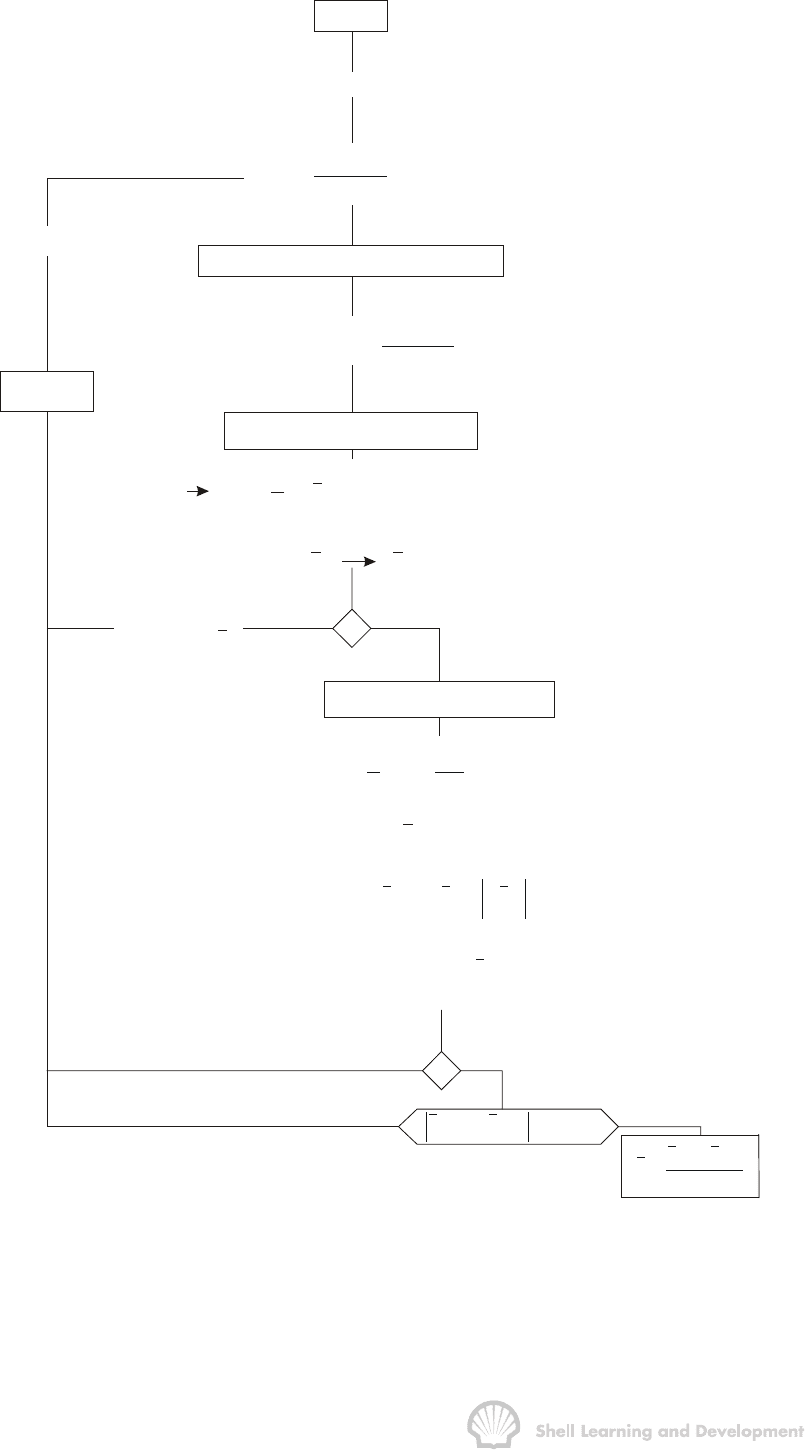
is determined using
equ. (8.61). The Horner buildup is plotted using this value of t
SSS
instead of the effective
flowing time. The MBH (or Dietz) method is then used to obtain an initial value of the
average pressure at the time of the survey (refer Chapter 7, sec.7). The
µ
c product is
re-evaluated at p, and t
SSS
and p re-estimated. For this second, and all successive
values of p, the material balance is applied to determine p
SSS
, the average pressure
t
SSS
hours before the well closure, using dG
p
= Q
l
t
SSS
for the final flow rate Q
l
and the
latest estimate of t
SSS
. A cycle is entered in which
µ
c is evaluated for the latest
determined value of p
SSS
and this continues until successive values of this pressure
do not differ by more than some tolerance value (e.g. TOL = 5 psi).
Each new estimate of t
SSS
leads to a new buildup plot and since m(p
*
) – m(p ) is
constant, a new value of
p is obtained on each occasion. In a worked example Kazemi
has shown that applying the above method can lead to a correction of 100 psi in the
value
p compared to the normal method in which
µ
c is evaluated as (
µ
c)
i
. The method
can also be used to correct the average pressure determined from a buildup test in a
solution gas drive reservoir which is below bubble point pressure.

REAL GAS FLOW: GAS WELL TESTING 288
k = 1
k
=
i
terat
i
on
counter
(c) = (c)
µ
k
i
µ
sss D
A
SSS
(c)
A
t(t)
.000264k
φµ
=
k
k
(c) = (c)
µ
kk-1
µ
(RE)-PLOT HORNER BUILDUP
EXTRAPOLATES TO m(p*)
k
SSS
ws
tt
m(p ) vs. log
t
+∆
∆
k
MBH m(p*) m( ) = constant = m log (C (t ) )p
k
ADASSS
k
m( ) p
k
p
k
k = 1 k > 1
k
p
k
(c) = (c)
µ
k
µ
MATERIAL BALANCE
k = 1k +
i
1SSS
i
p
p
dQt
ZZG
æö
=−
ç÷
èø
k
k
d(p
k
)
SSS
ppd(p)
−+
kkk
(c) (c)
µ
k
µ
SSS
p
k
k = 2 k > 2
k
+-
SSS SSS
pp TOL
−−
kk-1
pp
p
2
+
=
kk-1
TO m(p
*
)
k
Fig. 8.17 Iterative determination of
p in a gas well test analysis (Kazemi
10
)

REAL GAS FLOW: GAS WELL TESTING 289
8.12 PRESSURE BUILDUP ANALYSIS IN SOLUTION GAS DRIVE RESERVOIRS
The pressure buildup theory described in sec. 7 of the previous chapter was developed
for liquid flow and is therefore only appropriate for pressure surveys in undersaturated
oil reservoirs. For routine pressure surveys conducted throughout the producing
lifetime of the field, it is more likely that the average pressure will be below bubble point
so that there will be two phases, liquid oil and free gas, in the reservoir.
To analyse pressure buildup tests under these circumstances, Raghavan
17
has
suggested the use of the integral transformation
b
p
ro o
oo
p
k(S)
m(p) dp
B
µ
′
=
ò
(8.62)
which again is referred to as a pseudo pressure, only in this case applied to the flow of
oil, as denoted by the subscript "o". The k
ro
(S
o
) is the oil relative permeability, which is
a function of the oil saturation, while the other parameters,
µ
o
and B
o
are functions of
pressure. This leads to a certain degree of difficulty in determining the relation between
pressure and saturation required to evaluate equ. (8.62). Raghaven has shown that
this relationship can be obtained from the gas-oil ratio equation which expresses the
ratio of the reservoir gas to oil rates at the time of closure of the well, i.e.
sg rg
o
ogro
(R R )B k
(rb / gas)
B (rb / oil) k
µ
µ
−
=
or
rg
oo
s
gro g
k
B
RR
kB
µ
µ
=+ (8.63)
In this relationship, R is the fixed value of the producing GOR at the time of closure and
therefore, since k
rg
and k
ro
are functions of the oil saturation and B
o
, B
g
and R
s
are
functions of pressure, equ. (8.63) implicitly defines the pressure-saturation relationship.
The steps in evaluating the pseudo pressure integral, equ. (8.62), are then
1) Using the value of R at the time of the survey, determine the relation k
rg
/k
ro
as a
function of the pressure, using equ. (8.63).
2) Providing gas-oil relative permeability curves are available (k
ro
and k
rg
as
functions of S
o
, refer sec. 4.8) the relation between k
ro
and pressure can be
determined.
3) Using the trapezoidal rule, evaluate
m(p)
′
as a function of pressure, in the same
way as demonstrated in table 8.1.
It should be noted that this
m(p)
′
function only reflects conditions near the well at the
time of the survey and must be re-calculated for each pressure survey, as R varies.
Using the
m(p)
′
pseudo pressure, the constant terminal rate solution of the radial
diffusivity equation can be expressed in dimensionless form as

REAL GAS FLOW: GAS WELL TESTING 290
3
iwfDD
o
kh
7.08 10 (m (p ) m (p )) m (t ) S
q
−
′′ ′
×−=+
where
D
11
22
D D DA D(MBH) DA
4t
m(t) 2 t ln m (t )
π
γ
′′
=+ −
(8.64)
in which k is the effective permeability to oil in the presence of the connate water.
Raghavan has shown, using numerical simulation, that the
D
m
′
(t
D
) functions correlate
very well with the p
D
(t
D
) functions for liquid flow but, as in the case of real gas flow, the
match is better for small values of t
D
, before the boundary effects are felt.
It should also be noted that the compressibility used in the evaluation of t
DA
is the total
compressibility of the system. Above the bubble point this is simply
c
t
= c
o
S
o
+ c
w
S
wc
+ c
f
(5.22)
but below bubble point there must be additional components to account for the
presence of free gas and for the transfer of solution gas from the oil
18
. Thus for the oil,
a pressure drop ∆p will cause a reduction in the oil volume ∆B
o
and an increase in the
liberated gas volume B
g
∆ R
s
, and
os
og
o
BR
1
cB
Bp p
æ ∂∂ö
=− −
ç÷
∂∂
èø
The total compressibility, below bubble point pressure is therefore
gg
oso
tg wwcf
og
SB
SRB
cB cSc
BppBp
∂
æ ∂∂ö
=−−++
ç÷
∂∂ ∂
èø
(8.65)
in which, for a significant gas saturation, the last two terms can usually be neglected.
Because of the equivalence of form of the
D
m
′
functions, equ. (8.64), with the p
D
or m
D
functions, it is clear that the buildup theory must follow that detailed in Chapter 7,
sec. 7, for oil, and sec. 8.11 of this chapter, for gas. A Horner plot of m´(p
ws
) versus log
tt
t
+∆
∆
is made and the early linear trend extrapolated to determine m´(p
*
). The slope of
the linear section is
162.6 q
m
kh
=
and the skin factor can be calculated using equ. (7.52), with pseudo pressures
replacing the actual pressures in the equation. Again the MBH method can be used to
determine m(p)
′
and hence the average pressure p . Furthermore, if the flowing time
before the survey is very long, the correction method of Kazemi, described in the
previous section, can be applied to improve the estimate of
p .
