Dake L.P. Fundamentals of reservoir engineering
Подождите немного. Документ загружается.


OILWELL TESTING 221
lead to an instantaneous perturbation in the wellbore pressure without any associated
transient effects. This pseudo skin can be determined as a function of two parameters,
the penetration ratio b and the ratio h/r
w
, where
the total interval open to flow
b
the total thickness of the producing zone
=
and
w
h thickness of the producing zone
r wellbore radius
=
The latter definition is somewhat more complex than it appears since if the well is open
to flow over several sections of the total producing interval then h represents the
thickness of the symmetry element within the total zone. This point is made clear in
fig. 7.31 (a)-(c), which has been taken from the Brons and Marting paper and illustrates
three possible types of partial well completion. In all three cases the ratio
b = 30/150 = 0.2 while the ratio of h/r
w
is 150/.25 = 600 for case (a), 75/.25 = 300 for
case (b) and 15/.25 = 60 for case (c). Having thus determined the values of b and h/r
w
the pseudo skin S
b
can be determined using the chart presented as fig. 7.32. For the
three geometric configurations shown in fig. 7.31, the pseudo skin factors are
approximately 17, 15 and 9, respectively. Once the pseudo skin has been calculated it
must be subtracted from the total skin measured in the well test to give the mechanical
skin factor.
7.10 SOME PRACTICAL ASPECTS OF WELL SURVEYING
This section deals with some of the practical aspects involved in the routine pressure
testing of wells in a producing oilfield.
a) Wireline Pressure Recording Instrument
Due to its accuracy and ruggedness the most popular wireline pressure gauge is the
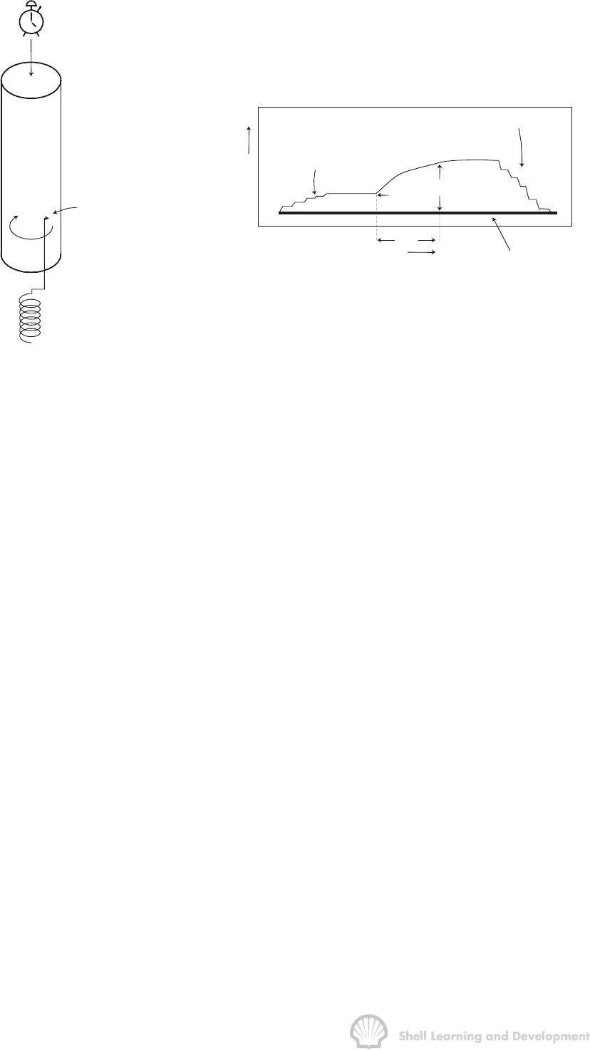
Amerada (RPG), a rough schematic diagram of this tool is shown in fig. 7.33(a). The
continuous trace of pressure versus time is made by the contact of a stylus with a chart
which has been specially treated on one side to permit the stylus movement to be
permanently recorded. The chart is held in a cylindrical chart holder which in turn is
connected to a clock which drives the holder in the vertical direction. The stylus is
connected to a bourdon tube and is constrained to record pressures in the
perpendicular direction to the movement of the chart holder. The combined movement
is such that, on removing the chart from the holder after the survey, a continuous trace
of pressure versus time is obtained as shown in fig. 7.33(b), for a typical pressure
buildup survey. Both the clock and pressure element can be selected to match the
maximum time and pressure anticipated for the particular survey. With careful
handling, regular calibration and accurate reading of the pressure chart with a
magnifying instrument, an accuracy of about 0.2 can be achieved.
OILWELL TESTING 222
CLOCK
VERTICAL CHART
MOVEMENT
∝ TIME
CHART
(a)
STYLUS
STYLUS MOVEMENT
∝ PRESSURE
BOURDON PRESSURE ELEMENT
PRESSURE
FLOWING PRESSURE-
DEPTH SURVEY
STATIC PRESSURE-
DEPTH SURVEY
TIME
t
∆
BASE LINE
p
wf
p
ws
(b)
Fig. 7.33 (a) Amerada pressure gauge; (b) Amerada chart for a typical pressure
buildup survey in a producing well
b) Conducting a Pressure Buildup Survey
Prior to the survey the well should be gauged to determine the gas/oil ratio and final
flow rate. The Amerada is calibrated, assembled and a base pressure line recorded on
the chart by disconnecting the clock and allowing the chart holder to fall slowly through
its full length while in contact with the stylus at atmospheric pressure and ambient
temperature. When subsequently measuring pressures after the survey, the readings
are made in the direction perpendicular to this base line.
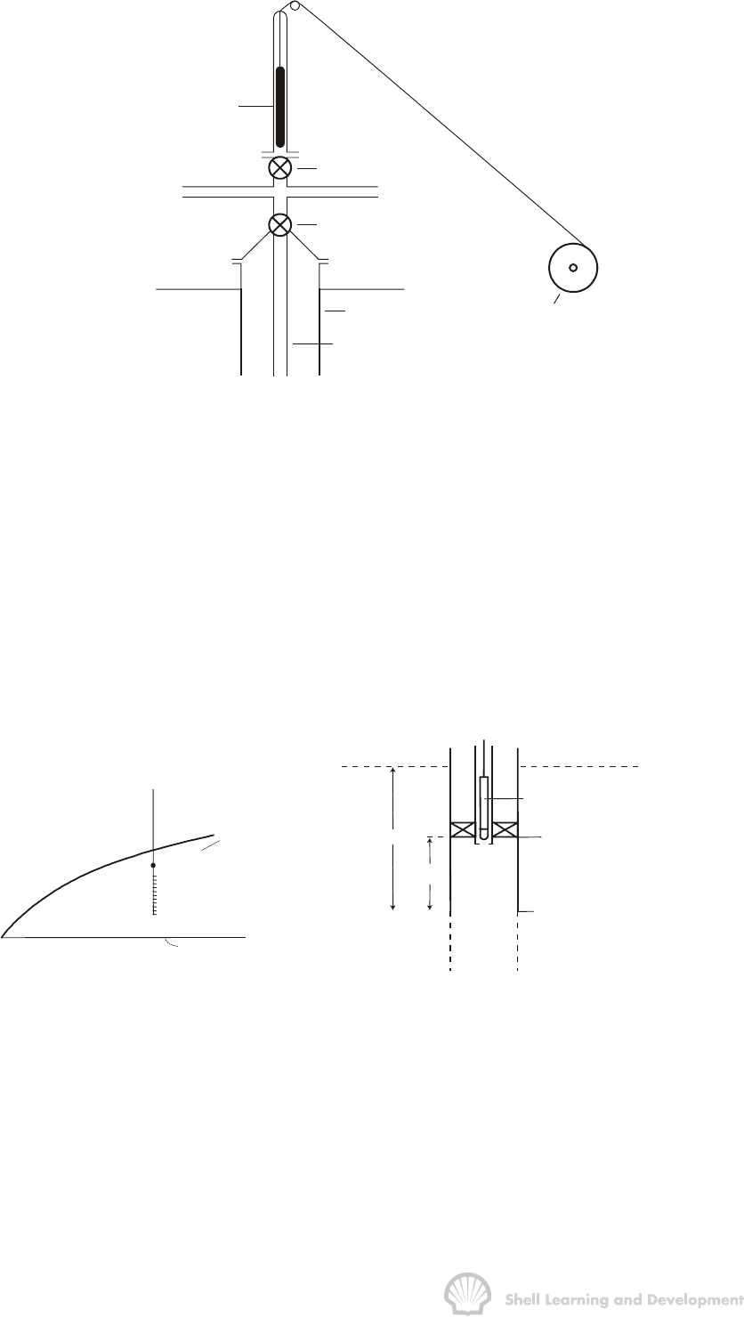
The Amerada is placed in a lubricator and the latter is flanged up to the wellhead as
indicated in fig. 7.34. When the gate valve beneath the lubricator is opened, the
Amerada can be run in on wireline against the flowing well stream. In a flowing or gas
lift well, it is common practice to stop at intervals of 1000 or 500 ft while running in with
the Amerada to record a flowing pressure survey. Each stop should be made for long
enough so that a series of pressure steps is discernible as shown in fig. 7.33 (b), and
therefore the length of time for each stop will depend on the scale of the clock being
used. The flowing pressure gradient, as a function of depth, measured in such a survey
is useful for production engineers in checking the lifting efficiency of the well.
Once the survey depth has been reached the bottom hole flowing pressure p
wf
is
recorded prior to closure. The well is then closed-in, usually at the surface, and the
OILWELL TESTING 223
AMERADA WITHIN
LUBRICATOR
GATE VALVE
MASTER VALVE
CASING
TUBING
WIRELINE WINC
H
Fig. 7.34 Lowering the Amerada into the hole against the flowing well stream
Amerada records the increasing pressure which can be related to the closed-in time ∆t,
fig. 7.33 (b).
At the end of the pressure buildup survey the Amerada is pulled out, with the well still
closed-in, and a static pressure survey is measured as a function of depth in a manner
similar to the flowing survey made while running in. In this case, stops should be made
at fairly short intervals of say 100-200 ft, close to the survey depth, and at wider
spaced intervals of 500-1000 ft, higher up the hole. The information gained from such a
survey can be vital in referring actual measured pressures in the well to a datum level
in the reservoir, in cases where it is not possible to conduct the buildup survey adjacent
to the perforated interval to be tested (refer Chapter 4, sec.6).
DATUM
MEASUREMENT DEPTH
OIL-WATER CONTACT
DATUM LEVEL
AMERADA
MEASUREMENT DEPTH
(p )
m
TOP PERFORATIONS
(a) (b)
h
H
Fig. 7.35 Correction of measured pressures to datum; (a) well position in the reservoir,
(b) well completion design
Consider, for instance, a survey conducted in the well shown in fig. 7.35 (a), (b). When
closed-in, the distribution of fluids in the well could vary between the two extremes
illustrated in fig. 7.36 (a), (b). In case (a), in which the well has been producing with a
watercut, the fluid distribution may be as indicated by the solid line, which is necessary
to obtain the correct pressure in the oil at the top of the perforations, the virtual oil
gradient being shown by the dashed line. Alternatively, there may be no water entering
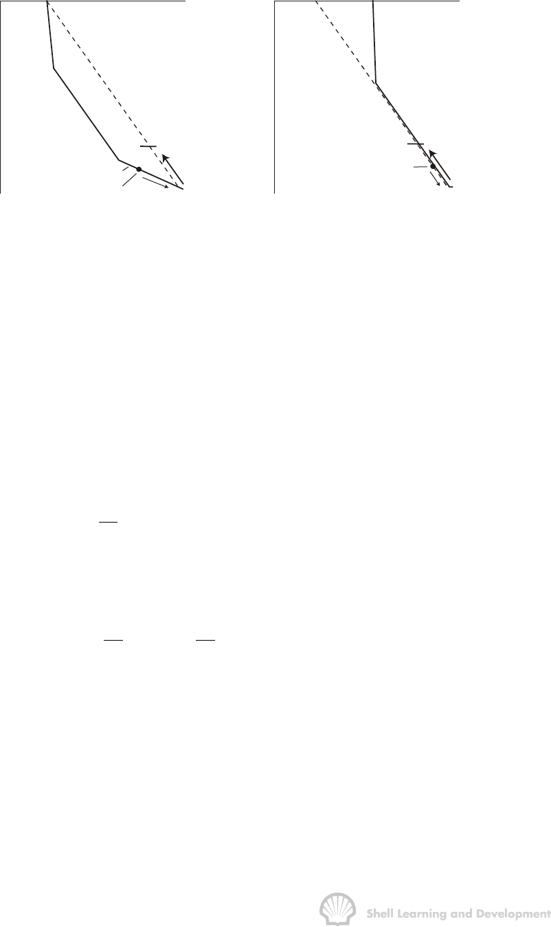
OILWELL TESTING 224
the well and the fluid and pressure distribution to the surface would then be as shown
in fig. 7.36(b), in which a rise in the static tubing head pressure occurs due to phase
separation.
THP
PRESSURE
GAS
OIL
WATER
MEASUREMENT DEPTH
DATUM
VIRTUAL OIL
GRADIENT
TOP PERFS.
(a)
(b)
THP
PRESSURE
GAS
OIL
DATUM
MEASUREMENT DEPTH
TOP PERFS.
Fig. 7.36 Extreme fluid distributions in the well; (a) with water entry and no rise in the
tubing head pressure, (b) without water entry and with a rise in the THP
Between these extremes, of course, there is an infinite range of possible fluid
distributions. The important thing is that the engineer should know the pressure
gradient in the wellbore fluid at the survey depth, which can only be obtained from the
static pressure - depth survey. If the well is completed as shown in fig. 7.3 (b), in which
for mechanical reasons it is not possible to conduct the buildup survey at the actual
reservoir depth, then, in order to relate the pressures measured in the borehole to the
datum level in the reservoir, it is first necessary to calculate the pressure at the top of
the perforations using the measured pressure gradient of the fluid in the borehole at
the survey depth, thus
()
()
m
perfs
well
dp
pp h
dz
æö
=+ ×
ç÷
èø
and thereafter, use the calculated oil gradient in the reservoir to correct to the datum
plane.
()
() ()
m
datum
well oil
dp dp
pp h H
dz dz
æö æö
=+ ×− ×
ç÷ ç÷
èø èø
7.11 AFTERFLOW ANALYSIS
When a well is closed in for a pressure survey, the closure is usually made at the
surface rather than at the sandface. Because the fluids in the flow string have a higher
compressibility than in the reservoir, production will continue at the sandface for some
finite time after the surface production has ceased. The time lag between closing in the
well at the surface and feeling the effects of closure in the reservoir is, to a large
extent, dependent upon the mechanical design of the well. If the well is completed with
a packed off annulus the volume of fluids in the flow string is considerably smaller than
OILWELL TESTING 225
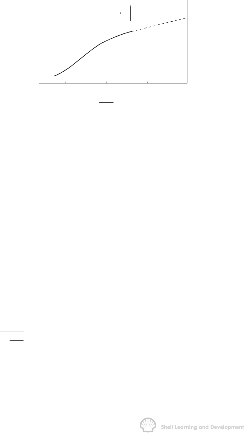
if no packer is used and the afterflow effects will be of less significance. Afterflow
distorts the early part of the Horner buildup plot, as shown in fig. 7.37.
p
ws
Buildup dominated
by afterflow
1000 100 10
1
p*
tt
t
+∆
∆
Fig. 7.37 Pressure buildup plot dominated by afterflow
Several theoretical methods have been presented for analysing the pressure response
during the afterflow period in order to determine kh and S. Due to the basic complexity
of the problem, it should be stated from the outset that the results obtained from any of
the various techniques are liable to be less accurate than those from the simple Horner
analysis of the straight line part of the buildup, once the afterflow has ceased.
In some cases, however, afterflow analysis provides a valuable means of obtaining
information about the reservoir. For instance, in several areas in the Middle East, wells
are capable of producing in excess of 50000b/d from limestone reservoirs. Because of
the very high kh values, which leads to very rapid pressure buildups, and the fact that
in many cases the wells produce through the casing, the afterflow period can
completely dominate the pressure buildup and afterflow analysis is the only method of
determining the essential reservoir parameters. The analysis methods which will be
described in this section are those of Russell
20
and McKinley
21
.
a) Russell Analysis
Russell developed a theoretical equation describing how the bottom hole pressure
should increase as fluid accumulates in the wellbore during the buildup. As a result of
this, he determined that the correct way of plotting the pressures during the part of the
buildup influenced by the afterflow was as
p
versus log t
1
1
Ct
∆
∆
−
∆
(7.77)
in which ∆p = p
ws
(∆t) − p
wf
(t) (psi),and ∆t is the closed in time (hrs). The denominator of
the left hand side contains a correction factor C to allow for the gradually decreasing
flow into the wellbore. This constant C must be selected by trial and error so that the
resulting plot is linear. This is illustrated in fig. 7.38. For very small values of ∆t the
buildup is dominated by the skin factor rather than afterflow. Therefore, not all the
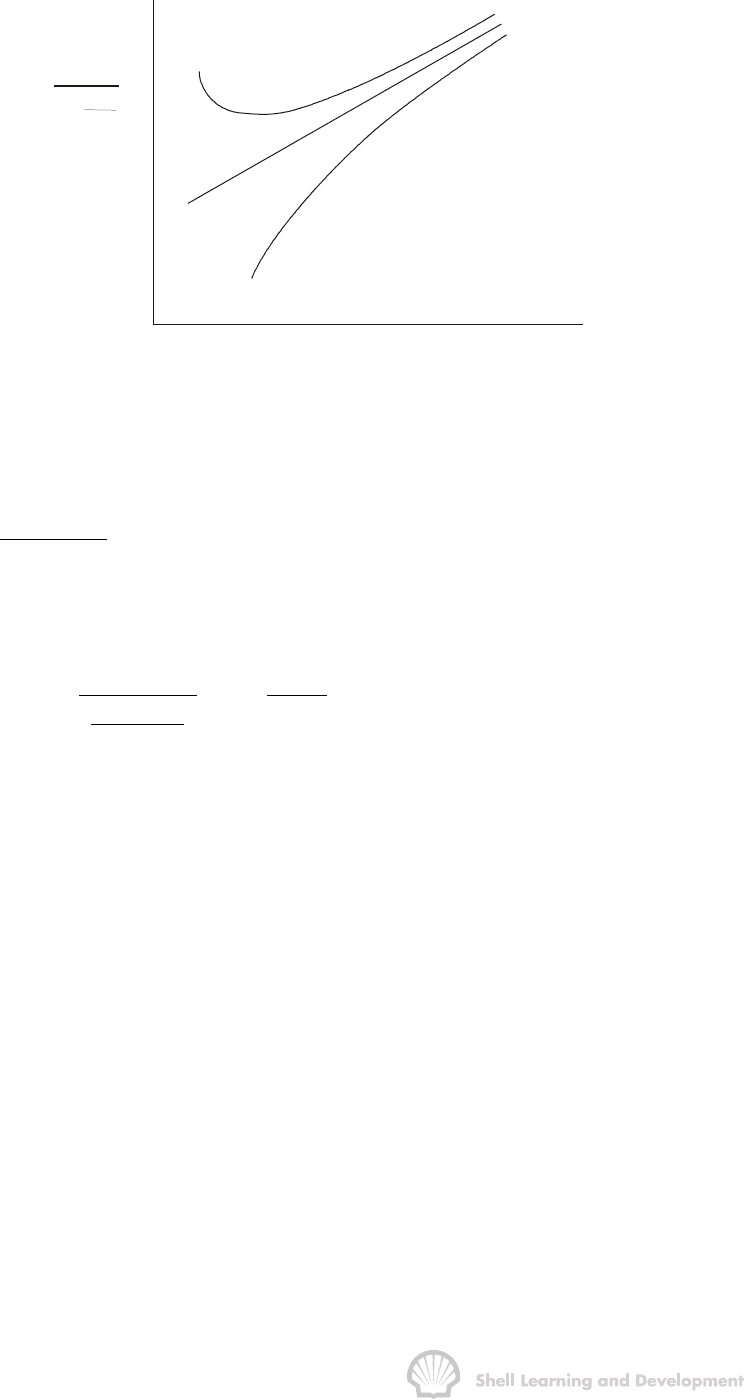
OILWELL TESTING 226
values of ∆p and ∆t can be used in this analysis. Russell recommends that plot should
be made only for values of ∆t measured after one hour of closed-in time.
(psi)
C - TOO SMALL
C - TOO LARGE
log ∆t
p∆
1 −
1
C∆t
Fig. 7.38 Russell plot for analysing the effects of afterflow
Having chosen the correct value of C. the slope of the straight line is measured
(m−psi/log cycle) and the formation kh value can be determined using the equation
o
162.6q B
kh
m
µ
= (7.78)
The skin factor can be calculated using the expression
wf (1 hr ) wf
2
w
pp
k
S1.151 log 3.23
11/Ct
cr
m
φµ
−
æö
ç÷
−
=−+
ç÷
−∆
ç÷
ç÷
èø
(7.79)
b) McKinley Analysis
To apply the McKinley method it is necessary to plot the pressure buildup in a special
manner and compare the resulting plot with so called "Type Curves" presented by
McKinley
21
, as shown in fig. 7.39.
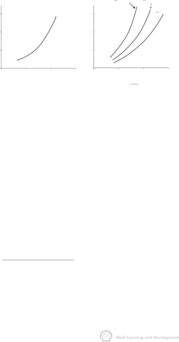
OILWELL TESTING 227
1
10 100 1000
1
10
100
1000
t
∆
(mins)
(psi)
∆p
(a)
t
∆
(mins)
1
10
100
1000
10
-4
10
-3
10
-2
10
-1
(b)
T
10 000
F
=
T
5 000
F
=
T
2 500
F
=
q
∆pF
Fig. 7.39 (a) Pressure buildup plot on transparent paper for overlay on (b) McKinley
type curves, derived by computer solution of the complex afterflow problem
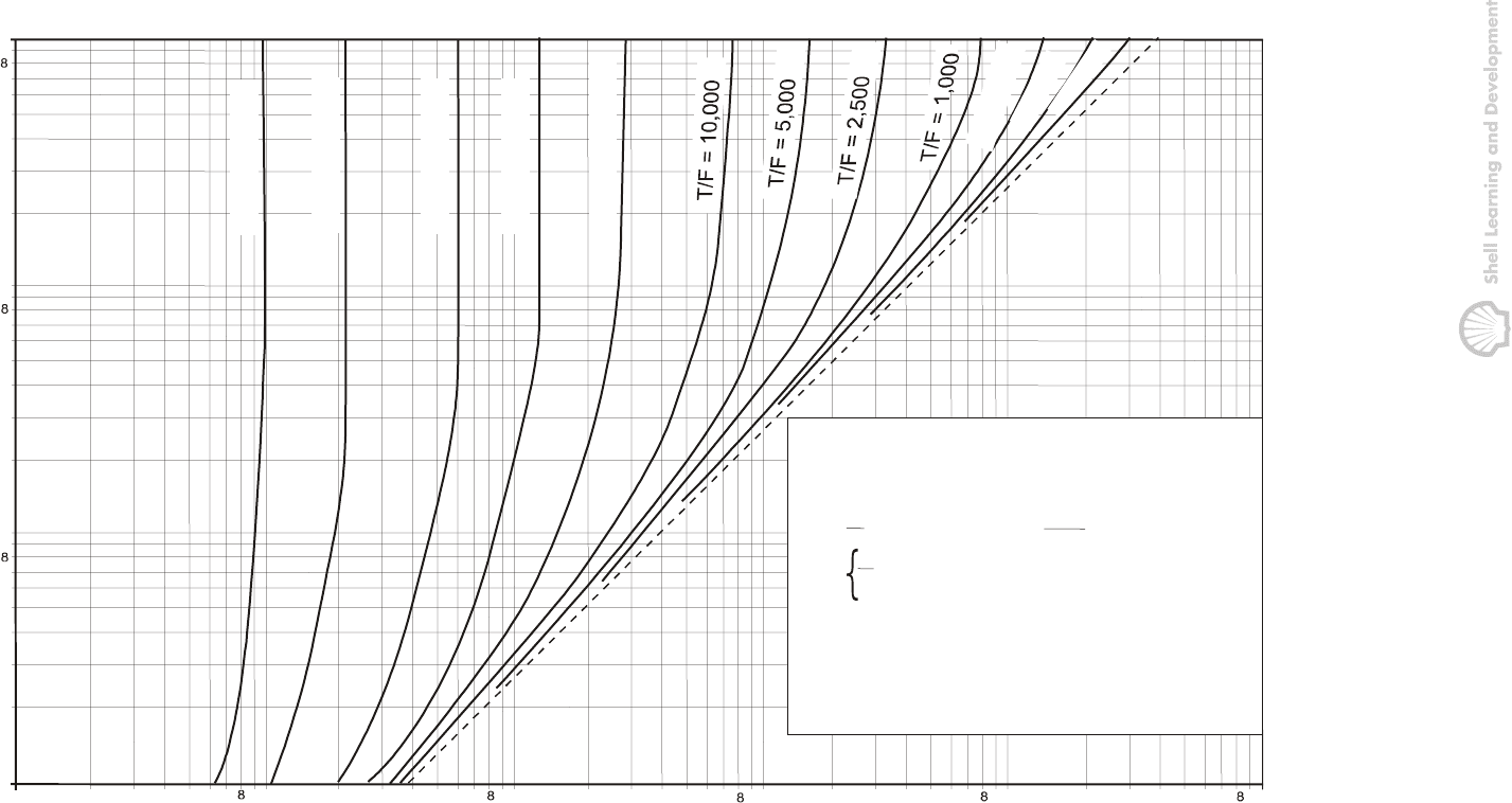
A set of McKinley type curves is included as fig. 7.40. These curves were computed by
numerical simulation of the complex afterflow process by forming a dynamic balance
between the capacity of the wellbore to store fluid and the resistance of the wellbore to
the flow of fluid from the reservoir.
All the curves were computed for a constant value of
2
w
cr / k
φµ
= 1.028×10
-7
cp.
sq ft/(mD psi), since in his original paper McKinley has demonstrated that the shape of
the type curves is insensitive to variation in the value of this parameter. Furthermore,
the curves were computed assuming no mechanical skin factor. If a well is damaged
this fact is evident since the pressure buildup plot will deviate from the McKinley type
curve and while the analysis does not explicitly determine the skin factor, it does allow
a comparison to be made between the kh values in the damaged and undamaged
parts of the reservoir.
The abscissa of fig. 7.40 is for the parameter ∆pF/q where
∆p=p
ws
(∆t) – p
wf
(t) (psi)
q = oil rate in rb/d
and F is the so called "wellbore parameter"
Wellbore area (sq.ft)
F (for partially liquid filled wells)
Wellbore liquid gradient (psi/ ft)
=
13
F Wellbore fluid compressibility (psi ) Wellbore volume (ft )
−
=×
(for fluid filled wells)
OILWELL TESTING 228
10
-4
10
-3
10
-2
10
-1
10
0
10
1
2345679
2
3
45
6
7
9
2
3
45
6
7
9
234567
92345679
2
3
4
5
6
7
9
10
2
3
4
5
6
7
9
100
2
3
4
5
6
7
9
1000
G
c
A
V
W
= Wellbore liquid gradient, psi/ft
= Wellbore fluid compressibility, (psi)
= Wellbore cross-sectional, area, sq ft
= Wellbore volume, bbls
-1
= Pressure change from flowing
pressure, psi
= Shut-in time, minutes
= Production rate, reservoir barrels per dayq
T
F
; For partially liquid filled wells
5.6 c V; For completely fluid-filled wells
W
=
∆
p = p - p
ws wf
∆
t
kh
µ
=
Wellbore Transmissibility,
mD - ft
cp
A
G
SHUT-IN TIME - ∆t MINUTES
T/F = 500,000
T/F = 250,000
T/F = 100,000
T/F = 50,000
T/F = 25,000
T
/
F
=
5
0
0
T
/
F
=
2
5
0
T
/
F
=
1
0
0
PRESSURE BUILDUP GROUP -
∆
∆
∆
∆ p f / q
Fig. 7.40 McKinley type curves for 1 min <∆
∆∆
∆t < 1000 min. (After McKinley
21
)
(Reproduced by courtesy of the SPE of the AIME)
OILWELL TESTING 229
In practice, the value of F is seldom explicitly calculated in the McKinley analysis. It is a
parameter which disappears by cancellation when calculating the wellbore
transmissibility.
Each type curve is characterised by a fixed value of T/F, where T is the transmissibility
= kh/
µ
mD.ft/cp.
The steps involved in a McKinley analysis, which is usually aimed at determining
transmissibilities in the damaged/stimulated zone close to the wellbore, and the
average for the formation away from the well, are as follows.
a) Make a table of values of ∆t, the closed in time (minutes), and the corresponding
values of ∆p = p
ws
(∆t) - p
wf
(t) (psi). Unlike the Russell method it is not necessary
to differentiate between the part of the buildup due to skin and that due to
afterflow, all values of ∆t and ∆p can be used.
b) Overlay the McKinley chart with a sheet of transparent paper and draw vertical
and horizontal axes to match those of the chart. The ordinate should have the
same log time scale as the McKinley chart but the abscissa, while using the
same log scale, should be plotted for the most suitable range of pressure values.
Plot the ∆t versus ∆p data on this transparent paper.
c) The transparent paper is then moved laterally over the McKinley chart, keeping
the abscissae together, until the early part of the pressure buildup coincides with
one of the type curves.
d) The value of the parameter T/F, characterising the type curve for which the match
is obtained, is noted.
e) Any one of the points on the pressure buildup, which also lies on the type curve,
is now used as a match point and the corresponding value of ∆pF/q is read from
the abscissa of the McKinley chart. Multiplying this value by the value of T/F
gives
pF T pT
qF q
∆∆
×=
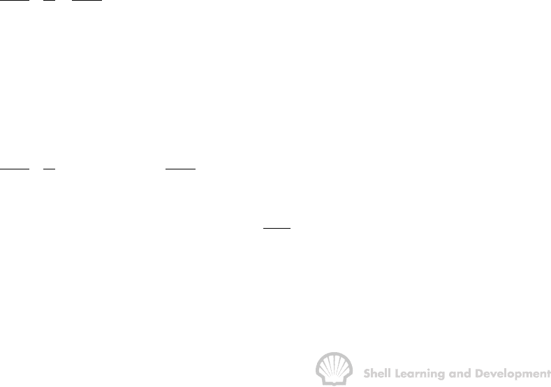
(7.80)
Since ∆p (psi) is known for the match point, then the transmissibility T can be
calculated from this latter expression. Finally, since T = kh/
µ
, the values of kh and
k can be determined. The procedure is illustrated in fig. 7.41.
Using the figures shown in this diagram
pF T pT
0.05 5000
qF q
∆∆
×= × =
If q = 500 rb/d, then T = 5000 × 0.05 ×
500
800
= 156 mD.ft/cp.
OILWELL TESTING 230
X
X
X
X
X
X
X
X
X
1000
100
10
1
10
-4
10
-3
10
-2
buildup plot
match point
p = 800 psi
∆
McKinley type
(curve (T/F = 5000)
p F
q
∆
= .05
p F
q
∆
∆t
(mins)
Fig. 7.41 Buildup plot superimposed on a particular McKinley type curve for
T/F = 5000
The transmissibility obtained in this manner is for the damaged or stimulated
region close to the wellbore, T
w
.
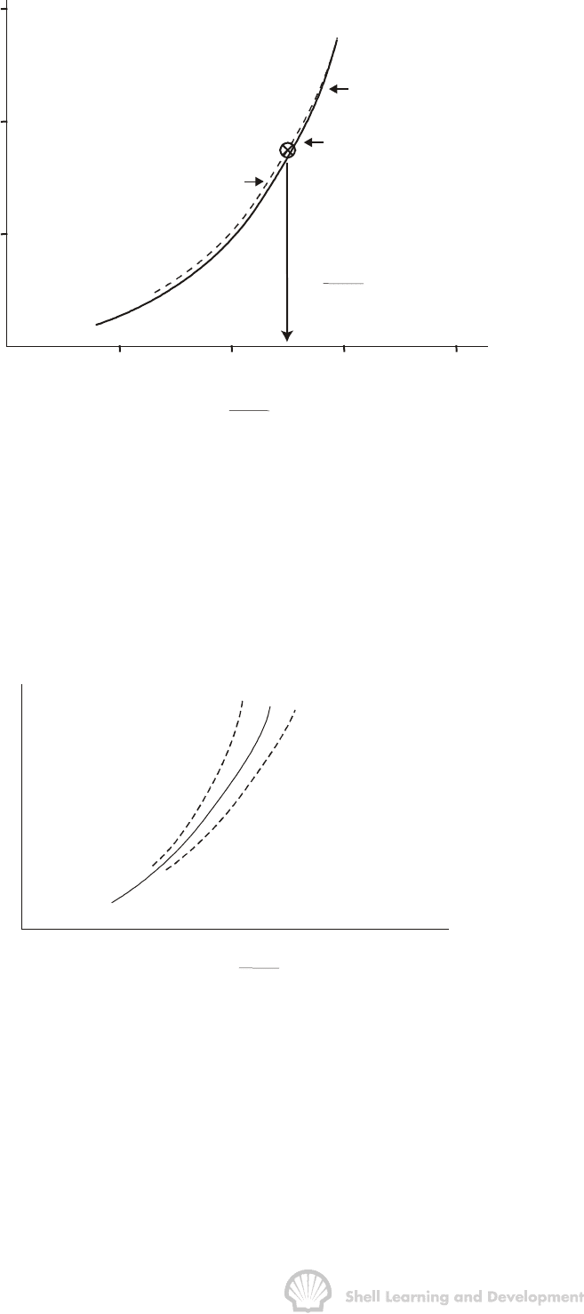
f) If, for large values of ∆t on the buildup plot, the pressure points trend away from
the McKinley type curve, this indicates the presence of a mechanical skin factor,
as shown in fig. 7.42.
p F
q
∆
t
(mins)
∆
S (positive)
S (negative)
Fig. 7.42 Deviation of observed buildup from a McKinley type curve, indicating the
presence of skin
Since the latter part of the buildup, for large ∆t, is not influenced by the skin it should
reflect the actual transmissibility of the formation beyond the damaged or stimulated
zone near the well.
Therefore, to obtain the formation transmissibility, T
f
, the late part of the buildup plot is
re-aligned with another of the type curves, for which the value of T/F is again noted.
