Dake L.P. Fundamentals of reservoir engineering
Подождите немного. Документ загружается.


OILWELL TESTING 211
The original paper on the subject was presented by Odeh and Jones
5
in which the
analysis technique is precisely as described above except that the
D
p functions in
equ. (7.69) were evaluated for transient flow as
()
D
1
2
DD
4t
pt ln
γ
=
(7.23)
This leads to the test analysis equation (with t in hours)
()
()
n
n
iwf
j
3
nj1
2
j1
on n w
pp
q
kh k
7.08 10 1.151 log t t log 3.23 0.87S
Bq q cr
µφµ
−
−
=
−
∆
æö
×= −+−+
ç÷
èø
å
(7.72)
which, providing the assumption of transient flow is appropriate for the test, will give a
linear plot of (p
i
−p
wf
)/q
n
versus Σ ∆q
j
/q
n
log(t
n
−t
j-1
), with slope m = 162.6
µ
B
o
/kh and
intercept m(log(k/
φµ
c
2
w
r ) −3.23 + .87S), from which k and S can be calculated.
It is frequently stated in the literature that the separate flow periods should be of short
duration so that transient flow conditions will prevail at each rate. While this condition is
necessary, it is insufficient for the valid application of transient analysis to the test.
Instead, the entire test, from start to finish, should be sufficiently short so that
transience is assured throughout the whole test period. The reason for this restriction is
that the largest value of the dimensionless time argument, for which the p
D
functions in
equ. (7.69) must be evaluated, is equal to the total duration of the test. This point is
illustrated in fig. 7.27 (b), which again demonstrates the basic principle of superposition
and shows that in evaluating the flowing pressure at the very end of the test there is
still a component of the pressure response due to the first flow rate to be included in
the superposed constant terminal rate solution. The following example will illustrate the
magnitude of the error that can be made by automatically assuming that a multi-rate
flow test can be interpreted using transient analysis techniques.
EXERCISE 7.8 MULTI-RATE FLOW TEST ANALYSIS
An initial test in a discovery well is conducted by flowing the well at four different rates
over a period of 12 hours as detailed in table 7.10.
Flowing time
(hours)
Oil rate
(stb/d)
p
wf
(psia)
0 0 3000(p
i
)
3 500 2892
6 1000 2778
9 1500 2660
12 2000 2538
TABLE 7.10

OILWELL TESTING 212
At the end of the flow test the well is closed in for a pressure buildup from which the
permeability is estimated as 610 mD. The available reservoir data and fluid properties
are listed below.
Drainage area A = 80 acres
Geometry
2
1
φ
=.22 B
o
= 1.35 rb/stb
h = 15 ft
µ
=1 cp
r
w
= .33 ft c = 21 × 10
-6
/psi
1) Analyse the test data to determine k and S using equ. (7.69) with the p
D
functions
evaluated using equ. (7.42) or (7.46)
2) Repeat the analysis evaluating the p
D
function for transient flow conditions,
equ. (7.23).
EXERCISE 7.8 SOLUTION
1) The general multi-rate test analysis equation, (7.69) can be expressed as
()
()
n
nj1
n
iwf
j
DD D
j1
nn
pp
q
mpttmS
qq
−
=
−
∆
=−+
å
where m = 141.2
µ
B
o
/kh
and p
D
()
nj1
DD
tt
−
− = p
D
(
'
D
t ) can be evaluated as
()
11 1
22 2
D D DA DA D(MDH) DA
2
w
4A
pt 2t lnt ln p (t)
r
π
γ
′′ ′ ′
=+ + −
(7.46)
i.e.
()
1
2
D D D(MDH) DA
pt p (t)
α
′′
=−
(7.73)
in which
D
262
w
.000264kt .000264 610 t
t
cr .22 1 21 10 (.33)
φµ
−
×
′
==
×× × ×
()
5
3.2 10 t hours=×
and
()
2
DA D w
t t r / A .01t hours=× =
The p
D
functions, equ. (7.73), are evaluated in table 7.11 for all values of the time
argument required in the test, and for a variety of geometrical configurations of the
80 acre drainage area in order to investigate the sensitivity of the results to variation in
shape.

OILWELL TESTING 213
2
1
4
1
Time
(hrs)
t
DA
α
(equ.7.73)
½ p
D(MBH)
p
D
½ p
D(MBH)
p
D
½ p
D(MBH)
p
D
3 .03 7.480 .098 7.382 .189 7.291 −.069 7.549
6 .06 8.015 .098 7.917 .381 7.634 −.151 8.166
9 .09 8.407 .071 8.336 .553 7.854 −.162 8.569
12 .12 8.739 .055 8.684 .690 8.049 −.177 8.916
TABLE 7.11
The test analysis is presented in table 7.12.
()
nj1
n
i
DD D
j1
n
q
pt t
q
−
=
∆
−
å
t
n
hrs
q
(stb/d)
p
wf
(psi)
iwf
n
pp
q
−
2
1
4
1
3 500 2892 .2160 7.382 7.291 7.549
6 1000 2778 .2220 7.650 7.463 7.858
9 1500 2660 .2267 7.878 7.593 8.095
12 2000 2538 .2310 8.080 7.707 8.300
TABLE 7.12
e.g. the complex summation for n = 3 is
()
()
()
()
()
()
993
96
3
DD DD D
j1
DD D
500 0 1000 500
pt pt t
1500 1500
1500 1000
pt t
1500
=
−−
=+ −
−
+−
å
in which the p
D
functions are taken from table 7.11 for the various geometries
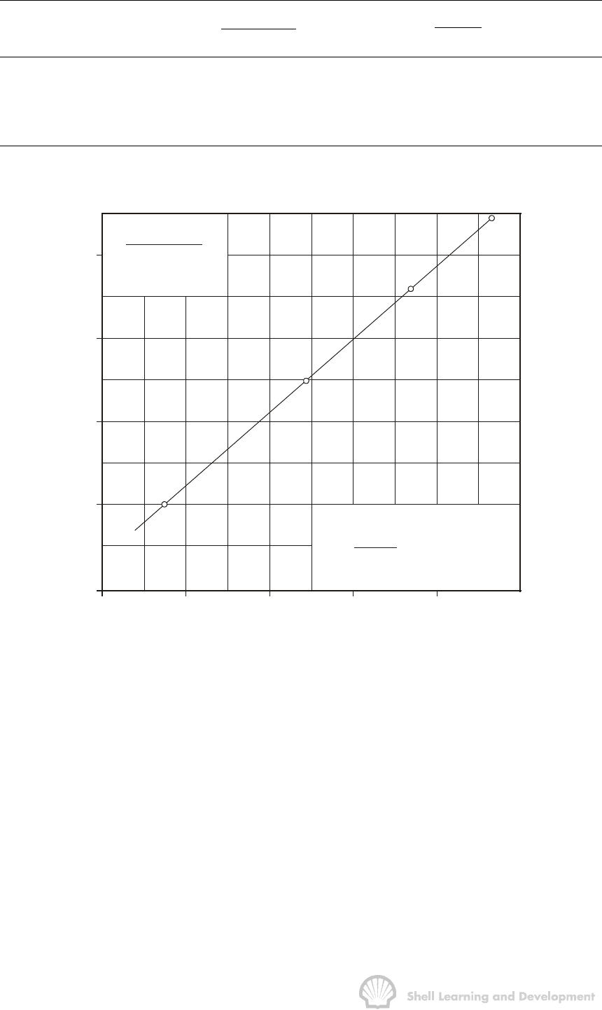
considered. The test results in table 7.12 are plotted in fig. 7.28. The basic reservoir
parameters derived from these plots are listed in table 7.13. In each case the intercept
on the ordinate has been calculated by linear extrapolation.
Geometry
Slope
m
Intercept
mS
k
(mD) S
2
1
.0124 .5280 594 2.7
.0360 −.0466 353 −1.3
4
1
0.199 .0655 639 3.3
TABLE 7.13

OILWELL TESTING 214
2) If the test is analysed assuming transient flow conditions, the evaluation would be as
set out in table 7.14.
.83.81.79.77.75.73
.20
.21
.22
.23
.24
2
4
1
1
Infinite reservoir and
circular geometry
X
X
X
X
−
n
iwf
n
pp
(psi/stb/d)
q
nj1
j
DD D
n
q
p(t t )
q
−
∆
−
å
Fig. 7.28 Illustrating the dependence of multi-rate analysis on the shape of the
drainage area and the degree of well asymmetry. (Exercise 7.8)
t
n
(hrs)
t
D
n
p
D
(t
D
)
()
nj1
n
iwf i
DD D
ji
nn
pp q
pt t
qq
−
=
−∆
−
å
39.6×10
5
7.292 .2160 7.292
6 19.2 " 7.639 .2220 7.466
9 28.8 " 7.842 .2267 7.591
12 38.4 " 7.985 .2310 7.690
TABLE 7.14
To facilitate comparison with the results from the first part of this exercise, the present
results have also been plotted in fig. 7.28 rather than making the more conventional
Odeh-Jones semi log plot, as specified by equ. (7.72). For the infinite reservoir case
the slope m = .0374 and calculated intercept mS = −.0573 which implies that
k = 340 mD
S = − 1.5
At first glance, the results of exercise 7.8 are somewhat alarming. Assuming that the
2:1 geometry is correct, as stated in the question, then there is an error of over forty
percent in the calculated permeability, and what is in fact a damaged well (S = 2.7)
appears to be stimulated (S = −1.5), merely as a result of applying transient analysis to
the same set of test data.

OILWELL TESTING 215
The reason for this disparity lies in the nature of the analysis technique itself. In plotting
the results according to equ. (7.71) the evaluation of the abscissa,
()
nj1
n
i
DD D
j1
n
q
pt t
q
−
=
∆
−
å
, automatically involves the boundary condition in the analysis,
since use of the p
D
function implies a knowledge of the geometrical configuration.
Therefore, unlike the buildup analysis, for which a unique plot of the observed data is
obtained, the multi-rate test analysis can yield a different plot for each assumed
boundary condition, as shown in fig. 7.28, and all the plots appear to be approximately
linear. The only time when a straight line is obtained, which has no dependence on the
boundary condition, is for the infinite reservoir case. Then the Odeh-Jones plot is
applicable which has as its abscissa,
()
n
j
nj1
j1
n
q
log t t
q
−
=
∆
−
å
equ. (7.72). The problem is, of
course, how can one be sure that transient analysis is valid without a knowledge of
several of the basic reservoir parameters, some of which may have to be determined
as results of the test analysis.
As clearly shown in the MBH charts, figs. 7.11-15, the crucial parameter for deciding
the flow condition is
DA
kt
t 0.000264
cA
φµ
=
(7.49)
If t
DA
is extremely small when evaluated for the maximum value of t (i.e. t = total test
duration) then it is probably safe to use the transient analysis technique. It is not
obvious, however, just how small this limiting value of t
DA
should be because this too
depends on the geometrical configuration. For a well positioned at the centre of a circle
or square the minimum value of t
DA
is 0.1, at which point there is a fairly well defined
change from pure transient to semi-steady state flow. For a well asymmetrically
positioned within a 2:1 rectangle, e.g. curve IV of the MBH chart, fig. 7.12 (which is the
correct geometrical configuration for exercise 7.8) the departure from purely transient
flow, in this case to late transient flow, occurs for t
DA
< 0.015. Similarly for the 4:1
geometrical configuration included in the exercise the departure occurs for t
DA
< 0.01.
In exercise 7.8, the relationship between t
DA
and the real time has a large coefficient of
0.01 (i.e. t
DA
= 0.01 t) . Th is results from the fact that the permeability is large and the
area relatively small and have been deliberately chosen so to illustrate the hidden
dangers in applying transient analysis techniques to multi-rate test results. After the
first 3-hour flow period the corresponding value of t
DA
is 0.03 and therefore there is
already a departure from transient flow for the 2:1 and the 4:1 geometries used in the
exercise. If it is assumed that the well is at the centre of a circle, however, transient
analysis can be applied throughout since the value of t
DA
corresponding to the entire
test duration of 12-hours is t
DA
= 0.12 and, as already noted, the departure from
transient flow for this geometry occurs for t
DA
= 0.1. The above points are clearly
illustrated in fig. 7.28 and in tables 7.11-14.
The majority of examples of multi-rate test analysis in the literature have, quite
correctly, been subjected to transient analysis. For instance, there is an example of a

OILWELL TESTING 216
multi-rate test in a gas well presented in the original Odeh-Jones paper
5
for a well
positioned at the centre of a circular shaped area of radius 3000 ft (A ≈ 650 acres) and
for which the permeability is 19.2 mD. In the example t
DA
= 9.2×10
-5
, and for the
geometry considered, transient analysis can be applied for a total of 1086 hours. It is in
cases where reservoirs are not continuous and homogeneous over large areas but
splintered into separate reservoir blocks on account of faulting that errors can occur in
assuming the infinite reservoir case is applicable in the test analysis.
One further, complication arises in connection with this type of analysis, and that is,
that in order to apply the correct technique, using the general p
D
function, equ. (7.42),
requires a knowledge of the permeability in order to calculate t
D
or t
DA
. In buildup
analysis this presents no problem since k can be readily calculated from the slope of
the linear section of the buildup plot. In multi-rate testing, however, this can prove more
difficult. Sometimes it is possible to separately analyse the initial flow period by plotting
p
wf
versus log t and applying the transient analysis technique described in exercise 7.2.
Unfortunately, in high permeability reservoirs this is very difficult to apply in practice,
since the pressure fall-off is initially very rapid. Under these circumstances it may be
necessary, and indeed is always advisable, to conduct a buildup at the end of the flow
test which tends to defeat one of the main purposes of the multi-rate test, namely, to
avoid well closure.
It is commonly believed that multi-rate flow tests can only be analysed if the initial
equilibrium pressure within the drainage volume is known. This is an unnecessary
restriction which has tended to limit the application of this technique to initial well tests
for which p
i
can be readily determined. The following analysis shows that, with minor
modifications to the method presented so far, the multi-rate test can be analysed with
only a knowledge of the bottom hole pressure and surface production rate prior to the
survey.
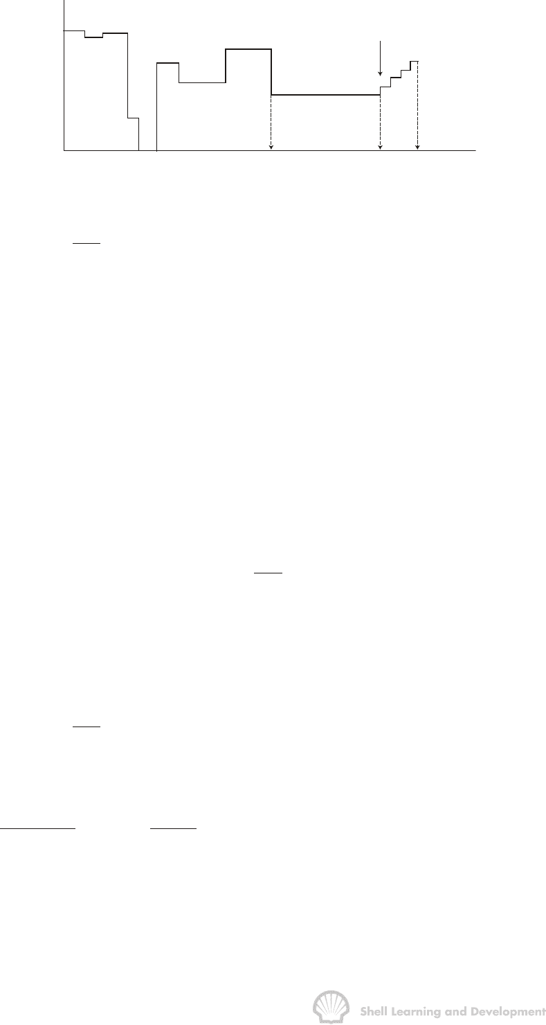
Suppose that a well with the variable rate history shown in fig. 7.29 is to be tested by
flowing it at a series of different rates.
Prior to the test the well is produced at a constant rate q
N
during the N
th
and final flow
period before the multi-rate test commences at time t
N
. Then, for any value of the total
time t
n
during the test, when the current rate is q
n
, the bottom hole flowing pressure
n
wf
p
can be calculated as
()
()
nnj1
n
3
iwf jDD D n
j1
o
kh
7.08 10 p p q p t t q S
B
µ
−
−
=
×−=∆−+
å
in which p
i
is the initial pressure at t = 0 and the summation includes all the variable
rate history up to and including the test itself. This equation can be subdivided as

OILWELL TESTING 217
Rate
Time
Start of multi-rate test
t
N-1
t
N
t
n
q
N
Fig. 7.29 Multi-rate test conducted after a variable rate production history
()
()
()
()
nNnj1
nj1
N
3
iwf jDD D D N
j1
o
n
jD D D n N
jN1
kh
7.08 10 p p q p t t t q S
B
qp t t q q S
δ
µ
δδ
−
−
−
=
=+
×−=∆+−+
+∆ − +−
å
å
(7.74)
in which
nnN
ttt
δ
=−
and
j1 j1 N
tttforjN1
δ
−−
=− ≥+
Then if the condition is imposed that (t
N
−t
N-1
)>> t
n(max)
, i.e. the last flow period before the
test commences is considerably greater than the total duration of the test itself, then
()()
Nnj1 Nj1
NN
jD D D D jD D D
j1 j1
qp t t t qp t t
δ
−−
==
∆−−≈∆−
åå
(7.75)
and
()
()
Nj1 N
N
3
jD D D N i wf
j1
o
kh
q p t t q S 7.08 10 p p
B
µ
−
−
=
∆−+≈× −
å
where
N
wf
p is the flowing pressure recorded immediately before the multi-rate test
commences.
Equation (7.74) can therefore be simplified as
()
()
()
Nn n j1
Nn
3
wf wf j D D D n n
j1 jN1
o
kh
7.08 10 p p q p t t q q S
B
δδ
µ
−
−
==+
×−=∆−+−
åå
and therefore a plot of
()
()
Nn
nj1
n
wf wf
j
DD D
jN1
nN nN
pp
q
versus p t t
qq qq
δδ
−
=+
−
∆
−
−−
å
(7.76)
should again be linear with slope m = 141.2
µ
B
o
/kh and the intercept on the ordinate
equal to mS. Using this modified technique provides a useful way of applying the multi-
rate flow test for routine well surveys. The only condition for its application is that the
flow period before the test should be much longer than the totai test duration. This

OILWELL TESTING 218
does not necessarily mean that flow should be under semi-steady state conditions at
this final rate. The condition is usually satisfied since the reliable analysis of a multi-
rate test, as already noted, requires that the total test duration should be brief so that
transient analysis can be applied.
As a demonstration of the effectiveness of this analysis technique, a test has been
simulated in a well for which the following data are applicable
Area drained 650 acres
h=50ft
geometry
r
e
≈3000 ft r
w
=.3 ft
B
o
= 1.2 rb/stb
k = 20 mD c = 15 × 10
-6
/ psi
φ
=.23
µ
=1 cp
p
i
= 3500 psia S = 2.0
Prior to the test the well had been producing for one year at 1000 stb/d and for a
second year at 400 stb at which time a multi-rate test was conducted as detailed in
table 7.15. The bottom hole flowing pressure prior to the test was
N
wf
p = 2085 psi.
Rate
stb/d
Cumulative time
hrs
Flowing
pressure
psia
600 4 1815
800 8 1533
1000 12 1244
1200 16 950
TABLE 7.15
For the above conditions the relationship between dimensionless and real time is
t
DA
= 5.41 × 10
-5
t (hours) and therefore, after the total test period of 16 hours
t
DA
= 8.65 × 10
-4
. This means that transient analysis can be safely applied to the test
since, for a well at the centre of a circle, transient conditions prevail until t
DA
≈ 0.1.
The test data in table 7.15 are analysed using the plotting technique of equ. (7.76), with
the p
D
functions evaluated as
()
D
111
222
DD DA
2
w
4t
4A
pt ln t ln
r
γ
γ
==+
(7.23)
The analysis is detailed in table 7.16, and the resulting plot shown as fig. 7.30.

OILWELL TESTING 219
Time
hrs
Rate
stb/d
p
wf
n
psi
Nn
wf wf
nN
(p p )
qq
−
−
p
D
(t
D
)
nj1
n
j
DD D
jN1
nN
q
p( t t )
qq
δδ
−
=+
∆
−
−
å
4 600 1815 1.350 5.968 5.968
8 800 1533 1.380 6.315 6.142
12 1000 1244 1.402 6.518 6.267
16 1200 950 1.419 6.662 6.366
TABLE 7.16
1.41
1.39
1.37
1.35
1.33
5
.
9
6
.
0
6
.1
6
.2
6
.
3
6
.
4
nj1
j
DD D
nN
q
p(t t )
qq
−
∆
δ−δ
−
å
Nn
wf wf
nN
(p p )
(q q )
(psi/stb/d)
−
−
Fig. 7.30 Multi-rate test analysis in a partially depleted reservoir
The slope and intercept of the straight line have values of 0.173 and 0.317,
respectively, from which it can be calculated that k = 19.6 mD and S = 1.8. These
values compare very favourably with the actual values of k = 20 mD and S = 2.0.
7.9 THE EFFECTS OF PARTIAL WELL COMPLETION
In deriving the basic diffusivity equation for liquid flow, equ. (5.20), it was assumed that
the well was completed across the entire producing interval thus implying fully radial
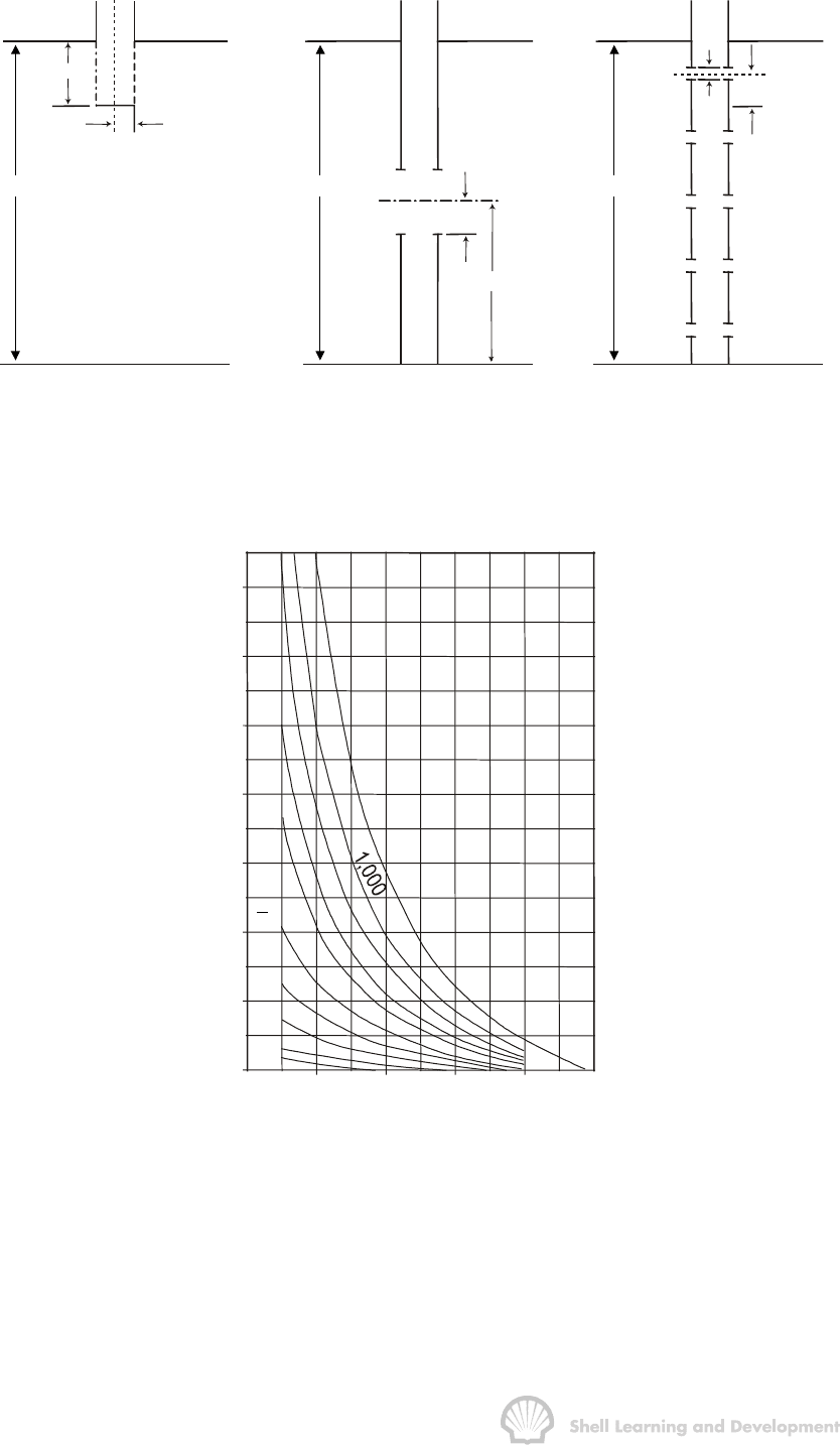
flow. If for some reason the well only partially penetrates the formation, as shown in
fig. 7.31 (a), then the flow can no longer be regarded as radial. Instead, in a restricted
region at the base of the well, the flow could more closely be described as being
spherical.

OILWELL TESTING 220
(a)
30 ft
0.25 ft
150 ft
(b)
150 ft
15 ft
75 ft
150 ft
6 ft
15 ft
(c)
Fig. 7.31 Examples of partial well completion showing; (a) well only partially
penetrating the formation; (b) well producing from only the central portion of
the formation; (c) well with 5 intervals open to production
(After Brons and
Marting
19
)
1
0
,
0
0
0
3
0
0
1
0
0
5
0
2
0
1
0
1
5
2
00.20.40.6
0.8
1.0
b
0
4
8
12
16
20
24
28
S
b
w
h
r
=
Fig. 7.32 Pseudo skin factor S
b
as a function of b and h/r
w
(After Brons and Marting
19
)
(Reproduced by courtesy of the SPE of the AIME)
Brons and Marting
19
have shown that the deviation from radial flow due to restricted
fluid entry leads to an additional pressure drop close to the wellbore which can be
interpreted as an extra skin factor. This is because the deviation from radial flow only
occurs in a very limited region around the well and changes in rate, for instance, will
