Czichos H., Saito T., Smith L.E. (Eds.) Handbook of Metrology and Testing
Подождите немного. Документ загружается.


308 Part B Chemical and Microstructural Analysis
SIMS instruments and their new ion sources make this
a very fast developing and fruitful area. New standards
in ISO are expected to be developed over the coming
years.
6.2 Surface Topography Analysis
The topography of a surface is the set of geometrical de-
tails that can be recorded through a measurement. Most
commonly, topography is either related to the mechan-
ical nature of the surface, typically involved in contact
situations, or to its electromagnetic nature, typically in-
volved in optical effects. Topography is of paramount
importance for the functional behavior of a surface,
strongly interplaying with material properties and op-
erating conditions.
Surface topography characterization is a powerful
tool in connection with design, manufacture, and func-
tion. As schematically illustrated in Fig. 6.15, it allows
one to link the functional behavior of a surface to
the microgeometry obtained from its generation. The
three main phases of surface topography characteriza-
tion are measurement, visualization, and quantification.
These phases encompass a number of basic steps,
nowadays prevalently involving digital techniques and
extensive use of computers: data acquisition, condi-
tioning, visualization, elaboration, and quantification.
In particular, quantification typically concerns the ge-
ometry of single surface features at micrometer or
nanometer scale, being based on the extraction of
parameters, curves, functions or basic geometrical fea-
tures from a representative profile or area on the surface.
Quantifying the microgeometries of surfaces after they
Generation
• Honing
• Injection molding
• Coating
• Grinding
• Etc.
Function
• Sealing
• Gloss
• Paintability
• Wear
Characterization
• Visualization
• Quantification
• Measurement
Design
• Surface engineering
• Tolerancing
• Etc.
Fig. 6.15 Surface topography characterization links de-
sign, generation, and function (after [6.189])
have been measured is important in all applications
of process control, quality control, and design for
functionality.
The principal methods of surface topography mea-
surement are stylus profilometry, optical scanning
techniques, and scanning probe microscopy (SPM).
These methods, based on acquisition of topography
data from point-by-point scans, give quantitative in-
formation on heights with respect to position. Other
methods such as scanning electron microscopy (SEM)
can also be used. Based on a different approach, the
so-called integral methods produce parameters repre-
senting some average property of the surface under
examination. A further classification distinguishes be-
tween contacting and noncontacting instruments. While
stylus instruments are inherently contacting methods
and optical instruments noncontacting methods, scan-
ning probe microscopes can be both contacting and
noncontacting. We shall describe the basics of each of
the methods later, but it is useful to outline the attributes
of the methods here so that the reader can focus early on
their method of choice.
In a stylus profilometer, the pick-up draws a sty-
lus over the surface at a constant speed, and an electric
signal is produced by the transducer. This kind of in-
strument can produce very accurate measurements in
the laboratory as well as in an industrial environment,
covering vertical ranges up to several millimeters with
resolutions as good as nanometric, with lateral scans of
up to hundreds of millimeters being possible. The sty-
lus is typically provided with a diamond tip with a cone
angle (total included angle) of 60
◦
or 90
◦
and a tip ra-
dius in the range 1–10 μm. The maximum detectable
slopes using a stylus instrument are, respectively, 60
◦
or 45
◦
. The spatial resolution achieved by this method,
generally in the range 2–20 μm, is limited by the tip
geometry, and depends on the actual surface slopes
and heights in the neighborhood of the point of con-
tact. Moreover, the force applied by the stylus on the
surface can generate plastic deformation on the sur-
face, making this method inapplicable to surfaces that
are soft or where even light scratches cannot be ac-
cepted.
Part B 6.2
Surface and Interface Characterization 6.2 Surface Topography Analysis 309
Optical scanning techniques encompass most typ-
ically optical profilometers, confocal microscopes, and
interferometers. The optical methods are noncontacting,
which allows measurements on soft surfaces. How-
ever, this kind of instrument is subject to measurement
errors related to achieving a useful reflection signal
from surfaces that are shiny or transparent to the light
source. Optical styli for profilometry can be based
on the autofocusing signal of a laser beam detector.
The beam has a spot diameter of about 1 μm, and
this kind of instrument is similar in use to conven-
tional stylus instruments, with vertical resolution of
approximately 5 nm. The maximum detectable slope
using an autofocusing stylus instrument is approxi-
mately 15
◦
. Laser scanning confocal microscopy is
another optical technique based on the focus detec-
tion principle, where one surface picture element (pixel)
is imaged at a time. Topography is reconstructed as
a stack of vertical optical sections, in a fashion sim-
ilar to computer tomography. Confocal microscopes
allow steep surface details to be assessed, the max-
imum detectable slope being up to 75
◦
. Confocal
microscopes have limited lateral resolution, and some
commercially available instruments even have limited
vertical resolution. Interference microscopy combines
an optical microscope and an interferometer objective
into a single instrument. These optical methods al-
low fast noncontacting measurements on essentially flat
surfaces. Interferometric methods offer subnanometer
vertical resolution, being employed for surfaces with
average roughnesses down to 0.1 nm and peak-to-valley
heights up to several millimeters. Interferometric mi-
croscopes are all limited with respect to the surface
slopes from the finite numerical apertures. Moreover,
the lateral resolution is limited by diffraction. The max-
imum detectable slope using interferometry amounts to
about 30
◦
.
Scanning probe microscopy, including atomic force
microscopy (AFM) and scanning tunneling microscopy
(STM), is based on a powerful class of tools for sub-
nanometric acquisition of topography data on very fine
surfaces. SPM uses a sharp probe scanning over the
surface while maintaining a very close spacing to the
surface. SPM allows measurements on surfaces with an
area up to approximately 100×100 μm
2
and that have
local variations in surface height which are less than ap-
proximately 10 μm. SPM is a three-dimensional (3-D)
microscopy technology in which the resolution is not
limited by the diffraction of light. The vertical reso-
lution of SPM is about 0.1 nm, while the horizontal
resolution for most AFM devices is typically 2–10 nm,
but it can be atomic. SPM requires minimal sample
preparation.
Scanning electron microscopy (SEM) can also be
used for qualitative surface topography analysis, pri-
marily based on the fact that SEM allows excellent
visualization achieved through the very high depth of
focus of this technique. However, SEM photographs are
still inherently two-dimensional (2-D), and no height
information can be extracted directly from the images.
The 3-D achieved by reconstructing from stereo pairs or
triplets can be used to evaluate surface topography, but
it is limited by a number of factors.
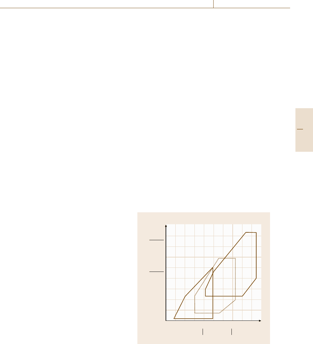
Figure 6.16 [6.190] shows a diagram of the spa-
tial resolutions of the different techniques that helps to
place the more popularly used methods in context. Ad-
ditional information is given in Table 6.8. Documentary
standards covering surface topography are published by
ISO. Updated information regarding the ISO standards
for surface texture can be found on the www.iso.org
website and by searching in the ISO catalogue under
17.040.20 Properties of surfaces and 17.040.30 Mea-
suring instruments. Surface texture is a topic covered
by the technical committee TC213 Geometrical Product
Specifications under the ISO, the homepage of which
can be found through the above-mentioned website.
Table 6.9 lists the titles of ISO standards published
Amplitude
Stylus
Optical
AFM
10
mm
nm
μm
mmnm
μm
1
100
10
1
100
10
1
0.10
0.01
0.1 1 10 10
2
11010
2
11010
2
10
3
Surface wavelength
Fig. 6.16 Diagram showing the vertical and horizontal res-
olution achievable with different instruments for surface
topography measurements (after Stedman [6.190])
Part B 6.2

310 Part B Chemical and Microstructural Analysis
Table 6.8 Resolutions and ranges of some techniques for surface topography analysis
Instrument Vertical axis Horizontal axes
Resolution (nm) Range (mm) Resolution (nm) Range (mm)
Stylus < 1 10 2000 > 100
Auto-focus < 5 1 1000 > 100
WLI 0.1 1 500 < 10
SEM 1 1 2 1
AFM < 0.1 0.01 1 0.1
WLI – white-light interferometry
SEM – scanning electron microscopy
AFM – atomic force microscopy
in the field of surface texture. Most standards cover
2-D profiling techniques, but also standards for 3-D
areal measurements are currently under publication by
Table 6.9 Published standards from ISO TC213 for surface texture
No. ISO standard Title [reference]
1 ISO 1302:2002 Geometrical product specifications (GPS) – Indication of surface texture in technical product
documentation [6.194]
2 ISO 3274:1996, (
∗
) Geometrical product specifications (GPS) – Surface texture: Profile method –
Nominal characteristics of contact (stylus) instruments [6.195]
3 ISO 4287:1997, (
∗
) Geometrical product specifications (GPS) – Surface texture: Profile method –
Terms, definitions, and surface texture parameters [6.196]
4 ISO 4287:1997Amd 1:2009, (
∗
) Peak count number [6.197]
5 ISO 4288:1996, (
∗
) Geometrical product specifications (GPS) – Surface texture: Profile method –
Rules and procedures for the assessment of surface texture [6.198]
6 ISO 5436-1:2000, (
∗
) Geometrical product specifications (GPS) – Surface texture: Profile method;
Measurement standards – Part 1: Material measures [198]
7 ISO 5436-2:2002, (
∗
) Geometrical product specifications (GPS) – Surface texture: Profile method;
Measurement standards – Part 2: Software measurement standards [6.199]
8 ISO 8785:1998 Geometrical product specification (GPS) – Surface imperfections – Terms, definitions,
and parameters [6.200]
9 ISO 11562:1996, (
∗
) Geometrical product specifications (GPS) – Surface texture: Profile method –
Metrological characteristics of phase-correct filters [6.201]
10 ISO 12085:1996, (
∗
) Geometrical product specifications (GPS) – Surface texture: Profile method –
Motif parameters [6.202]
11 ISO 12179:2000 Geometrical product specifications (GPS) – Surface texture: Profile method –
Calibration of contact (stylus) instruments [6.203]
12 ISO 13565-1:1996, (
∗
) Geometrical product specifications (GPS) – Surface texture: Profile method; Surfaces having
stratified functional properties – Part 1: Filtering and general measurement conditions [6.204]
13 ISO 13565-2:1996, (
∗
) Geometrical product specifications (GPS) – Surface texture: Profile method; Surfaces having
stratified functional properties – Part 2: Height characterization using the linear material ratio
curve [6.205]
14 ISO 13565-3:1998 Geometrical product specifications (GPS) – Surface texture: Profile method; Surfaces having
stratified functional properties – Part 3: Height characterization using the material probability
curve [6.206]
15 ISO/TS 16610-1:2006 Geometrical product specifications (GPS) – Filtration –
Part 1: Overview and basic concepts [6.207]
16 ISO/TS 16610-20:2006 Geometrical product specifications (GPS) – Filtration – Part 20: Linear profile filters:
Basic concepts [6.208]
ISO.Table6.10 presents a list of ISO standards under
development related to surface topography. Essential
textbooks covering the area are [6.191–193].
Part B 6.2

Surface and Interface Characterization 6.2 Surface Topography Analysis 311
Table 6.9 (continued)
No. ISO standard Title [reference]
18 ISO/TS 16610-22:2006 Geometrical product specifications (GPS) – Filtration – Part 22: Linear profile filters:
Spline filters [6.209]
19 ISO/TS 16610-28:2010 Geometrical product specifications (GPS) – Filtration – Part 28: Profile filters:
End effects [6.210]
20 ISO/TS 16610-29:2006 Geometrical product specifications (GPS) – Filtration – Part 29: Linear profile filters:
Spline wavelets [6.211]
21 ISO/TS 16610-30:2009 Geometrical product specifications (GPS) – Filtration – Part 30: Robust profile filters:
Basic concepts [6.212]
22 ISO/TS 16610-31:2010 Geometrical product specifications (GPS) – Filtration – Part 31: Robust profile filters:
Gaussian regression filters [6.213]
23 ISO/TS 16610-32:2009 Geometrical product specifications (GPS) – Filtration – Part 32: Robust profile filters:
Spline filters [6.214]
24 ISO/TS 16610-40:2006 Geometrical product specifications (GPS) – Filtration – Part 40: Morphological profile filters:
Basic concepts [6.215]
25 ISO/TS 16610-41:2006 Geometrical product specifications (GPS) – Filtration – Part 41: Morphological profile filters:
Disk and horizontal line-segment filters [6.216]
26 ISO/TS 16610-49:2006 Geometrical product specifications (GPS) – Filtration – Part 49: Morphological profile filters:
Scale space techniques [6.217]
27 ISO 25178-6:2010 Geometrical product specifications (GPS) – Surface texture: Areal –
Part 6: Classification of methods for measuring surface texture [6.218]
29 ISO 25178-601:2010 Geometrical product specifications (GPS) – Surface texture: Areal –
Part 601: Nominal characteristics of contact (stylus) instruments [6.219]
30 ISO 25178-602:2010 Geometrical product specifications (GPS) – Surface texture: Areal –
Part 602: Nominal characteristics of noncontact (confocal chromatic probe)
instruments [6.220]
31 ISO 26178-701:2010 Geometrical product specifications (GPS) – Surface texture: Areal –
Part 701: Calibration and measurement standards for contact (stylus) instruments [6.221]
Note (
∗
): Standard amended by technical corrigendum. Published corrigenda are: ISO 3274:1996/Cor 1:1998; ISO 4287:1997/Cor
1:1998; ISO 4287:1997/Cor 2:2005; ISO 4288:1996/Cor 1:1998; ISO 5436-2:2001/Cor 1:2006; ISO 5436-2:2001/Cor 2:2008; ISO
11562:1996/Cor 1:1998; ISO 12085:1996/Cor 1:1998; ISO 13565-1:1996/Cor 1:1998; ISO 13565-2:1996/Cor 1:1998
Table 6.10 Standards under development
No. ISO standard Title [reference]
1 ISO 1302:2002/DAmd 2 Indication of material ratio requirements [6.222]
2 ISO/DIS 16610-21 Geometrical product specifications (GPS) – Filtration – Part 21: Linear profile filters:
Gaussian filters [6.223]
3 ISO/CD 25178-1 Geometrical product specifications (GPS) – Surface texture: Areal –
Part 1: Indication of surface texture [6.224]
4 ISO/DIS 25178-2 Geometrical product specifications (GPS) – Surface texture: Areal –
Part 2: Terms, definitions, and surface texture parameters [6.225]
5 ISO/DIS 25178-3.2 Geometrical product specifications (GPS) – Surface texture: Areal –
Part 3: Specification operators [6.226]
6 ISO/DIS 25178-7 Geometrical product specifications (GPS) – Surface texture: Areal –
Part 7: Software measurement standards [6.227]
7 ISO/DIS 25178-603 Geometrical product specifications (GPS) – Surface texture: Areal – Part 603: Nominal char-
acteristics of noncontact (phase-shifting interferometric microscopy) instruments [6.228]
8 ISO/DIS 25178-604 Geometrical product specifications (GPS) – Surface texture: Areal – Part 604: Nominal char-
acteristics of noncontact (coherence scanning interferometry) instruments [6.229]
9 ISO/CD 25178-605 Geometrical product specifications (GPS) – Surface texture: Areal – Part 605: Nominal char-
acteristics of noncontact (point autofocusing) instruments [6.230]
Part B 6.2
312 Part B Chemical and Microstructural Analysis
Traverse unit
Pick-up Transducer Amplifier A/D Filtering
Parameter
calculation
Profile
Stylus
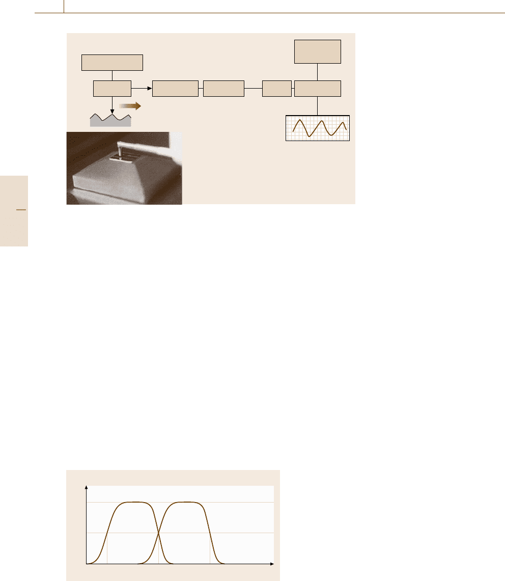
Fig. 6.17 Operational scheme for
a stylus profilometer; A/D = analog-
to-digital converter
6.2.1 Stylus Profilometry
General Introduction
The most well-known surface profilometer in the
manufacturing industry is the stylus instrument used
for conventional two-dimensional roughness measure-
ments. This kind of instrument, shown in Fig. 6.17,
has existed for over 60 years, and it yields a high de-
gree of accuracy, robustness, and user-friendliness. In
a typical surface tester, the pick-up draws the stylus
over the surface at a constant speed, and an electri-
cal signal is produced by the transducer, which can
be piezoelectric, inductive or laser interferometric. The
signal is amplified and digitized for subsequent data
processing such as filtering and parameter calculation.
In a more comprehensive laboratory stylus system, par-
allel tracings can be made over the workpiece, allowing
reconstruction of a whole surface area, in order to per-
form so-called three-dimensional surface topography
characterization. The versatility of the stylus instrument
is underlined by the ability to use this instrument on
Amplitude (%)
Roughness Waviness
Wavelength
λ
f
λ
c
λ
s
50
100
0
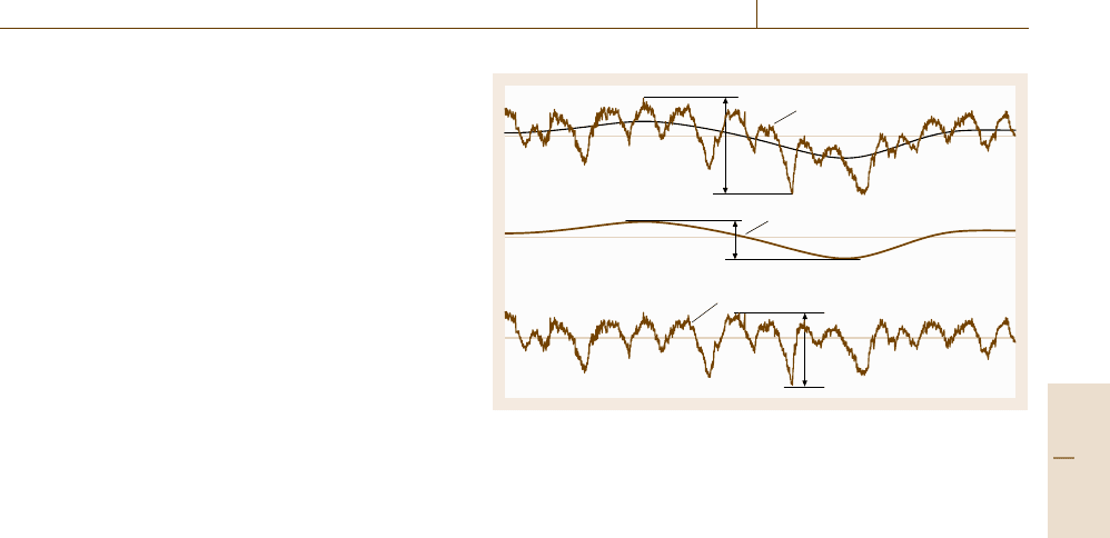
Fig. 6.18 Transmission characteristic of roughness and
waviness profiles using ISO filters (after [6.196])
all kinds of items, irrespective of orientation, and to
mount the pick-up on other machines, such as a coor-
dinate measuring machine or a form tester, to achieve
measurement of the surface topography over complex
workpieces. The stylus is provided with a diamond
tip with a total cone angle of 60
◦
or, more com-
monly, 90
◦
. Standardized values for the tip radius are
2, 5, and 10 μm, but other values are also used. Stylus
instruments feature vertical ranges of up to several mil-
limeters, with best resolutions at nanometric level and
scans of up to hundreds of millimeters possible. The
standardized values for the maximum load correspond-
ing to the above-mentioned radii are 0.7, 4, and 16 mN,
respectively. In many cases, a tracing speed of 0.5mm/s
is used.
Measurement and Filtering
When tracing a surface profile, a stylus instrument
works as schematically shown in Fig. 6.17. Filters are
used to separate roughness from waviness and form.
ISO operates with three different types of profile that
can be extracted from the acquired profile through
filtering: primary P-profile, waviness W-profile, and
roughness R-profile. Filters are useful in that they per-
mit the user to focus on wavelength components that
are important from a functional point of view. Modern
filter definitions introduced in ISO standards are based
on digital Gaussian cut-off filters characterized by be-
ing phase-correct and robust to single features such as
scratches. Referring to Fig. 6.18 and [6.196], ISO op-
erates with cut-off filters with nominal wavelengths λ
s
,
λ
c
,andλ
f
, where the index “s” refers to sampling, “c”
to cut-off, and “f” to form. An ISO filter is character-
ized by the wavelength at which it transmits 50% of
Part B 6.2
Surface and Interface Characterization 6.2 Surface Topography Analysis 313
the amplitude. As illustrated in Fig. 6.18, the three fil-
ters λ
s
, λ
c
,andλ
f
delimit the wavelength intervals for
the roughness and waviness profiles by creating two
filter windows. As an alternative, parameters can be cal-
culated on the basis of the so-called primary profile,
which results from eliminating the short-wave compo-
nents only, by using the λ
s
filter (λ
s
is used to eliminate
high-frequency components along with the mechanical
filtering effect from the stylus tip radius). As indicated
on the figure, the filters are not sharp but instead pro-
duce a progressive damping of the signal.
The data obtained from a measured surface are typ-
ically processed as follows.
1. A form fit, such as a least-squares arc or line (best
fit), is applied to the data in order to remove the
form.
2. The ultrashort-wave components are removed using
a λs filter. The result is the primary profile, from
which P-parameters can be calculated.
3. The primary profile is passed through a λ
c
filter with
a specific cut-off value that separates waviness from
roughness.
4. The resultant roughness or waviness profile is then
processed to calculate the roughness or waviness
parameters.
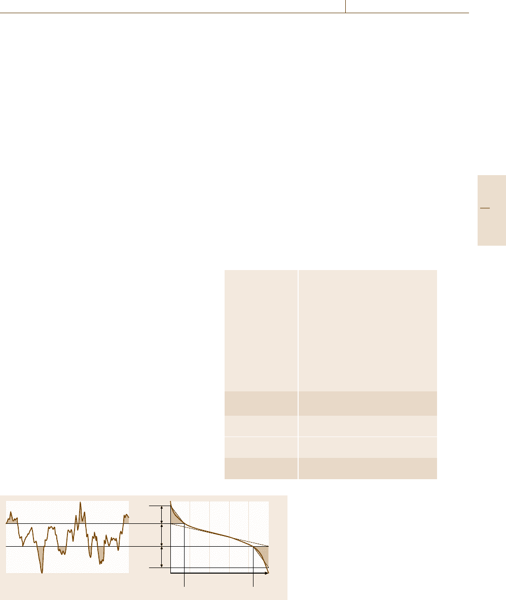
The result of filtering is illustrated in Fig. 6.19.
ISO 4287 operates with a number of standardized el-
ements used for parameter calculations: the mean line,
which is the reference line from which the parameters
are calculated, such as the mean line for the roughness
profile, which is the line corresponding to the longwave
profile component suppressed by the profile filter λ
c
;the
sampling length l
P
, respectively l
W
and l
R
, which is the
length in the direction of the X-axis used to identify the
irregularities characterizing the profile; and the evalua-
tion length l
n
, generally defined by ISO as five times the
sampling length (Pt , Wt,andRt shown in Fig. 6.19 are
calculated over the evaluation length). More advanced
methods of filtering are described in the new series of
ISO 16610 standards [6.207–217].
Visualization
The very first step in surface topography analysis con-
sists of a visualization of the microgeometry, either as
single profiles or as surface areas, to provide realistic
representations of the surface. The usefulness of such
an approach for qualitative characterization is well rec-
ognized: often the image inspection, possibly aided by
some enhancement techniques, can be assumed as the
P-profile
W-profile
R-profile
Pt
Wt
Rt
Fig. 6.19 Primary P-profile, waviness W-profile, and roughness
R-profile
only aim of the analysis. Indeed, the image conveys
a vast amount of information, which can be easily inter-
preted by an experienced observer; even a single profile
contains a large amount of relevant information, and
moreover in a condensed way by adopting different
scales for the horizontal and vertical axes. The pas-
sage from profile two-dimensional analysis to surface
three-dimensional analysis enlarges the possibilities for
gaining knowledge and representing the surface texture.
Many techniques have been developed to display the
sampled data, with the possibility of enhancing some
particular features, such as
•
contour plots, color plots, and grayscale mapping,
techniques borrowed from soil cartography to rep-
resent the surface heights,
•
isometric and dimetric (as in Fig. 6.15) projections,
where the single data points are interconnected with
all the neighboring points by straight or curved
lines. Projections can be modified by the scales and
projection angles, for enhancement of amplitudes,
texture, etc.,
•
inversion and truncation techniques, whereby the vi-
sual interpretation of the projections is enhanced
through data manipulation. Other manipulation
techniques are used, for example, to emphasize sur-
face slopes.
Quantification of Surface Texture
Quantitative assessment of surface texture can be very
useful in relation to process control, tolerance verifi-
cation, and functional analysis. Nevertheless, it must
be undertaken with care, since interpretation of mere
parameters can lead to wrong conclusions. Unless the
Part B 6.2

314 Part B Chemical and Microstructural Analysis
topographic nature of the surface under consideration
is known, it is strongly recommended that quantitative
characterization should only be used in connection with
a visual examination of the surface topography, as de-
scribed above.
2-D Parameters Covered by ISO Standards. Con-
ventional roughness parameters, which are those most
commonly known to quantify surface texture, are often
referred to as 2-D parameters, since they are computed
on the basis of single profiles containing information
in two dimensions (horizontal and vertical). The 2-D
surface texture area has been totally revised by ISO,
with the introduction of several new international stan-
dards [6.189, 194, 195, 198–206, 231]. According to
current ISO terminology, as mentioned in connection
with filters, the concept of surface texture encom-
passes roughness, waviness, and the primary profile.
In the following, an overview is presented of the ex-
isting ISO parameters for surface texture. Only ISO
parameters are considered here, since they adequately
cover what can be quantified through 2-D parameters.
A more complete review of parameters can be found
in the monographs [6.187–189]. Conventional 2-D pa-
rameters are described in the current ISO standard
ISO 4287 [6.197], while other 2-D parameters are cov-
ered by ISO 12085 [6.202]andISO 13565 [6.204–206].
ISO 1302 [6.194] prescribes a detailed indication of
surface texture tolerances on technical drawings, with
indication of the measurement specifications to follow
when verifying tolerances.
Conventional 2-D Parameters. ISO 4287 defines three
series of 14 parameters each: P-parameters for the un-
filtered profile, R-parameters for the roughness profile,
and W-parameters for the waviness profile; see Ta-
ble 6.11 and [6.197]. Filtering to obtain the R and W
profiles is introduced in the same standard and speci-
fied in [6.201]. Only examples of some parameters are
given in this section. The reader should refer to the
standard for complete definitions of each parameter.
Table 6.11 Profile parameters defined by ISO 4287 (1997)
Amplitude parameters
Distance
Hybrid Curves and
Top–valley Mean value parameters parameters related parameters
Roughness
parameters
Rp Rv Rz Rc Rt Ra Rq Rsk Rku RSm RΔq Rmr(c) Rδc Rmr
Waviness
parameters
Wp Wv Wz Wc Wt Wa Wq Wsk Wku WSm WΔq Wmr(c) Wδc Wmr
Structure
parameters
Pp Pv Pz Pc Pt Pa Pq Psk Pku PSm PΔq Pmr(c) Pδc Pmr
Conventional 2-D surface texture parameters are de-
fined in ISO 4287, but their value ranges are addressed
in ISO 4288 [6.198]. ISO 4288 uses five sampling
lengths as default for roughness profile parameters, in-
dicating how to recalculate their upper and lower limits
based on other numbers of sampling lengths. It should
be noted that the same terminology is used in ISO 4287
and ISO 4288 to indicate the parameters computed over
one sampling length and over five sampling lengths,
respectively. It should be also noted that wavelengths
under 13 μm and amplitudes of less than 25 nm are
not covered by existing ISO standards, which there-
fore disregard typical ranges of interest in usual AFM
metrology. However, since the ranges of definition seem
to be dictated by the physical possibilities of existing
stylus instruments, it can be assumed that the defini-
tions can also be extended to values below those, but
this must be investigated.
•
Ra is the most widely used quantification parame-
ter in surface texture measurement. It has also been
known in the past as the center line average (CLA)
or, in the USA, as the arithmetic average (AA). Ra
is the arithmetic average value of the profile depar-
ture from the mean line within a sampling length,
which can be defined as
Ra =
1
L
L
0
|
z(x)
|
dx ≈
1
n
n
i=1
|
z
i
|
. (6.42)
Here, z is the height from the mean line defined in
Fig. 6.19.
•
Rq, corresponding to the root mean square (RMS),
is preferred to Ra for modeling purposes. Rq is
the geometric average value of the profile departure
from the mean line within a sampling length, which
can be defined as
Rq =
1
L
L
0
[z(x)]
2
dx ≈
1
n
n
i=1
(
z
i
)
2
. (6.43)
Part B 6.2
Surface and Interface Characterization 6.2 Surface Topography Analysis 315
•
Rp is the maximum height of the profile above the
mean line within a sampling length.
•
Rv is the maximum depth of the profile below the
mean line within a sampling length.
•
Rz is the maximum peak-to-valley height of the pro-
file within the sampling length.
•
Rt is a parameter which basically has the same def-
inition as Rz but the definition of which is based on
the total assessment, or evaluation, length (l
n
). The
evaluation length covers by default five sampling
lengths, see ISO 4288 [6.198].
•
RSm (mean spacing) is the mean width of the pro-
file elements at the mean line within the sampling
length.
Other Parameters Defined by ISO. Other parameters
defined by ISO standards are the motif parameters and
the bearing curve parameters. ISO 12085 [6.202] con-
cerns parameters calculated through profile evaluation
using the motif method, so far only used by the French
motor industry. The method is based on dividing the
unfiltered profile into geometrical features, character-
ized by peaks, that may merge or remain unaltered
depending on their relative magnitudes, and thus calcu-
lating a number of roughness and waviness parameters.
It should be noted that waviness and roughness in
ISO 12085 do not refer to the same definitions used
for the conventional parameters defined in ISO 4887.
ISO 13565 describes two sets of parameters extracted
from the bearing curve, and was specifically devel-
oped to characterize stratified surfaces with different
functional properties at different depths. ISO 13565-
1[6.204] describes filtering. Parameters developed by
the German motor industry are defined in ISO 13565-
2(Fig.6.20 and [6.178]), while ISO 13565-3 describes
the parameter set developed by the US engine manufac-
turer Cummins [6.195,198,199,201,203,206,231,232].
3-D Parameters. Parameters calculated over an area
are referred to as areal, or 3-D, parameters. Currently,
Profile
0 10080 %604020
Mr1 Mr2
Rvk
Rk
Rpk
Fig. 6.20 Definition of bearing curve
parameters according to ISO 13565-
2:1996 (after [6.205]). Vertically, the
bearing curve is divided into three
zones, each described by a parameter:
Rpk(peaks), Rk (core), and Rvk (val-
leys). Horizontally, two parameters
are defined: Mr1andMr2 (material
portions)
3-D surface texture measurement is the object of a num-
ber of ISO standards currently under development.
Based on the research carried out within the European
Program [6.233], a set of 3-D parameters has been pro-
posed [6.234, 235]. These parameters are denoted by
S instead of R to indicate that they are calculated over
a surface. Table 6.12 gives an overview of the so-called
field parameters currently under consideration by ISO.
Most of the parameters of the set are derived from the
corresponding 2-D parameters, while three are uniquely
devised for surfaces. For example, the parameters Sa
and Sq are calculated using equations similar to, re-
spectively, (6.42)and(6.43). The reader should refer
to the ISO documents or to the above-mentioned re-
search reports for complete definitions of each param-
eter. Note that in ISO 25178 [6.236] conventional pro-
filometry is referred to as line-profiling methods, while
3-D surface characterization is called areal-topography
methods.
Table 6.12 3-D Parameters by ISO – Field parameters
Height parameters Arithmetical mean height Sa (μm)
Root-mean-square height of the scale-
limited surface Sq (μm)
Skewness of the scale-limited surface
Ssk
Kurtosis of the scale-limited surface
Sku
Maximum peak height Sp(μm)
Maximum pit height Sv (μm)
Maximum height of the scale-limited
surface Sz (μm)
Spatial parameters Autocorrelation length Sal (μm)
Texture aspect ratio Str
Hybrid parameters Root-mean-square gradient
of the scale-limited surface Sdq
Developed interfacial area ratio
of the scale-limited surface Sdr
Other parameters Texture direction of the scale-limited
surface Std (deg)
Part B 6.2
316 Part B Chemical and Microstructural Analysis
6.2.2 Optical Techniques
Many different measuring instruments based on optical
techniques exist [6.191, 193, 237, 238]. In this section,
the three most important ones are described: optical
stylus profilometry, confocal microscopy, and interfer-
ometry. Some issues are of importance to all optical
microscopy methods [6.239].
•
Material response: optical probing is only possi-
ble when a signal above the detector threshold is
received, which is determined by the material’s re-
flectivity.
•
Lateral resolution: this is limited by light diffrac-
tion. For an instrument numerical aperture NA and
a light wavelength λ, the limit d is given by [6.196]
d =
1.22λ
NA
. (6.44)
•
Maximum detectable slope: this depends on the kind
of reflection (specular or diffused), which in turn de-
pends on the surface topography and material, as
well as on the objective working distance and nu-
merical aperture.
•
Wavelength of full-amplitude modulation: this
quantity is intended as the maximum aspect ratio of
a measurable surface structure.
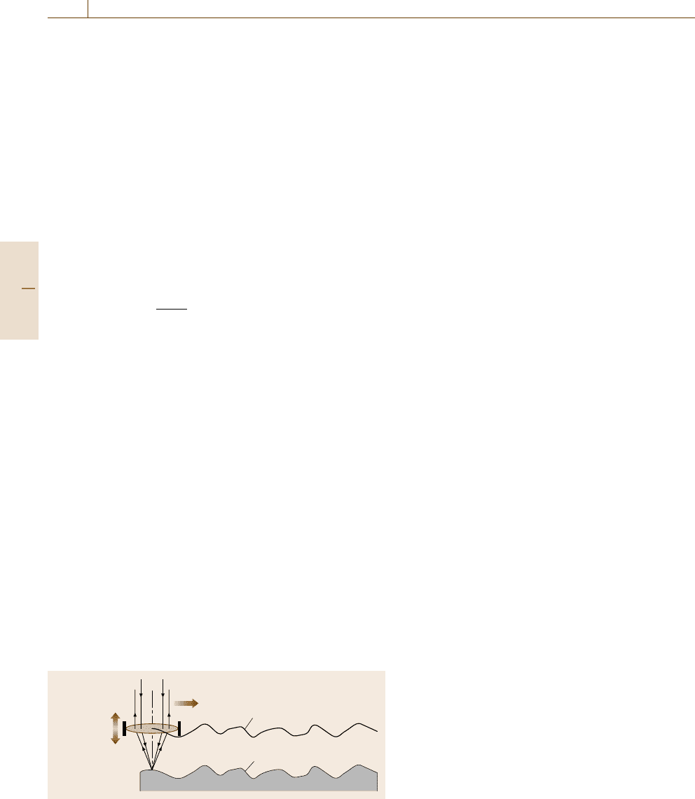
Optical Stylus Profilometry
Optical styli for profilometry can be based on the auto-
focusing signal of a laser beam detector. A laser beam
with a spot diameter of about 1 μm is focused onto
a point on the surface through a lens characterized by
a high numerical aperture (NA). The scattered light is
collected by the same lens on a focus detector, which
operates a control system. When the detector moves
horizontally, the controller, normally piezoelectric,
modifies the distance of the lens from the surface so as
to keep the beam focused. Consequently, the movement
Piezodrive
system
Lens trajectory
Profile
Fig. 6.21 Operating principle of the autofocusing method (after
[6.237])
of the lens follows the surface at a constant separation
distance, and its trajectory describes the surface profile,
as shown in Fig. 6.21. This kind of instrument is similar
in use to conventional stylus instruments, with vertical
resolution of approximately 5 nm. The optical method
is noncontacting, which allows measurements on soft
surfaces. However, this kind of instrument is connected
to some problems related to achieving a useful reflec-
tion signal from surfaces that are shiny or transparent
to the laser beam. The measurements obtained with the
autofocusing method do not always correlate very well
with those obtained with the stylus method [6.235,237],
as the optical method tends to overestimate the peak
heights and the stylus method to underestimate the val-
ley heights of the surface. The optical stylus method
was found to work well on very flat samples, but when
measuring roughnesses below 1 μs it was very prone to
error. The maximum detectable slope using an autofo-
cusing stylus instrument is approximately 15
◦
.
Confocal Microscopy
Confocal microscopy is an optical technique based on
the focus detection principle. It is routinely applied in
biological sciences, where relatively thick biological
samples, such as cells in tissue, are investigated using
fluorescence. However, it is also suitable for 3-D topog-
raphy assessment, when the reflected light is detected
rather than the emitted fluorescence. Here, the technique
is presented with reference to the reflection mode of
operation with a laser light source. The working prin-
ciple is easily seen by referring to Fig. 6.22, where key
components and optical ray diagrams are sketched (the
scanner which moves the laser spot on the surface is not
shown) [6.239].
Confocality consists in that both the light source
pinhole P1 and the detector pinhole P2 are focused on
the specimen. In laser scanning confocal microscopy
one surface picture element (pixel) is imaged at a time.
The final image is therefore built up sequentially. This
has relevant consequences for the application of this
technique to topography measurement; the measure-
ment time is negatively affected while the maximum
detectable surface slope is increased. Topography is re-
constructed as a stack of vertical optical sections, in
a fashion similar to computer tomography. In other
words, it is built by overlapping a number of opti-
cal slices with normal vectors aligned with the optical
axis. A single optical slice contribution to the final
topography is given by all of the pixels where re-
flection occurs. The two pinholes shown in Fig. 6.22
allow, in principle, the detection of light back from
Part B 6.2
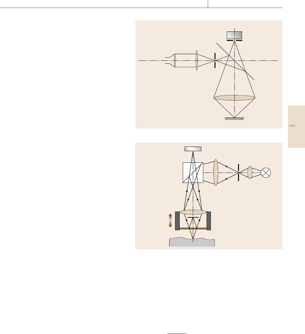
Surface and Interface Characterization 6.2 Surface Topography Analysis 317
the focal plane. Stray light should be stopped here
and should not reach the detector. This would be
strictly true for an infinitesimally small pinhole, but
the finite size always allows some amount of out-
of-plane light to be collected by the photodetector.
The pinhole diameter can be adjusted by the opera-
tor; practical values for the diameter in reflection-mode
confocal microscopy go down to the diffraction limit
givenby(6.44). As a consequence, optical slices have
a finite thickness. As regards the designs of con-
focal microscopes, some systems are provided with
monochromatic (laser) illumination; others are based
on xenon lamps which emit white light. The latter
source allows detection by means of a charge-coupled
device (CCD) sensor, with no scan being required in
the lateral plane. As concerns laser scanners, galvano-
metric scanning mirrors are used to move the laser
spot laterally, without physical table motion. The drive
of the vertical axis determines the vertical resolution.
With a piezo actuator, ranges of a few hundred mi-
crons are possible with resolution of a few nanometers.
When a direct-current (DC) motor drives the objective,
a range of up to 100 mm can be covered with reso-
lution of about 100 nm. Confocal microscopes allow
steep surface details to be assessed, the maximum de-
tectable slope being up to 75
◦
. Confocal microscopes
have limited lateral resolution, and some commercially
available instruments even have limited vertical resolu-
tion [6.239].
Interference Microscopy
Interference microscopy combines an optical micro-
scope and an interferometer objective into a single
instrument. Interferometric methods offer subnanome-
ter vertical resolution, and are employed for surfaces
with average roughnesses down to 0.1 nm and peak-to-
valley heights of up to several millimeters.
Interferometry is a well-known optical principle
that is widely used in metrology, which has recently
also been applied to surface metrology [6.237]. Ba-
sically, interferometric systems are derived from the
Fizeau interference microscope, as shown in Fig. 6.23.
A light beam is sent through a microscope objec-
tive onto the sample surface. A part of the incident
beam is reflected back by a semitransparent refer-
ence surface. The beams coming from the sample
surface and the reference surface are projected onto
the CCD detector, where they interfere. A piezoelectric
transducer moves the objective and the interferometer
vertically, causing fringe modulation. The intensity at
each point of the interference pattern is proportional
Laser source
Objective lens
Sample
Beam splitter
Detector
P1
P2
Fig. 6.22 Confocal principle
CCD
Beam splitter
Piezoelectric
transducer
Reference surface
Light source
Sample
Fig. 6.23 Optical layout of an interferometric measuring system
(after [6.237])
to
I(x, y) =cos[ϕ(x, y) +α(t)], (6.45)
where ϕ(x, y) is the initial phase and α(t)isthe
time-varying phase. The initial phase at each point is
calculated from the fringe modulation, and the corre-
sponding height is obtained using
z(x, y) =
ϕ(x, y)λ
4π
, (6.46)
where λ is the wavelength of the light source. Two main
interferometric techniques are commonly used in con-
nection with surface measurements [6.239]
Part B 6.2
