Chung Y.-W. Practical guide to surface science and spectroscopy
Подождите немного. Документ загружается.


87
5.4 EXPERIMENTAL ASPECTS
Q
UESTION FOR
D
ISCUSSION.
Some molecules adsorb on surfaces
forming commensurate structures, while others do not. What does this
tell us about the strength of adsorbate–surface interaction compared
with adsorbate–adsorbate interaction?
5.4 EXPERIMENTAL ASPECTS
Low-energy electron diffraction studies are performed using retarding
field optics (please refer to Chapter 1 for specifics of the retarding field
analyzer). Monoenergetic electrons (10–200 eV) are directed through a
metal tube at ground potential (drift tube) from the axis of the LEED
optics to the sample surface. The bias on the repeller grid is set to
repel all scattered electrons except those having the same energy as
the incident electrons. The collector is coated with a phosphor and
biased at a large positive potential on the order of several kilovolts.
The elastically scattered electrons, after passing through the repeller
grids, are then accelerated towards and strike the fluorescent screen
with several-keV energies. This arrangement therefore gives a visual
display of the diffraction pattern. The symmetry and positions of the
diffraction spots give immediately the symmetry and size of the surface
unit cell in real space. The intensity of the diffraction spot as a function
of the electron energy and temperature gives information on the posi-
tions of atoms in the unit cell and the amplitude of surface atom
vibrations, respectively.
In quantitative LEED studies, diffraction spot intensities are mea-
sured by a video camera or some position-sensitive detectors. One
implementation of the latter technique is to replace the phosphor screen
by a microchannel plate coupled with a resistive anode plate. Each
electron passing through the repeller impinges on the microchannel
plate, which consists of an array of small (10–30 m diameter) electron
multipliers. The incident electron is amplified by ⬃10
5
times at the
exit end of the microchannel plate. The current pulse then strikes the
anode, which is coated with a resistive film laid on a ceramic substrate
with current collectors at four corners. The division of currents to these
four corners is directly related to the location at which the electron
strikes the detector. Proper electronics and software can be incorporated
to view the diffraction pattern in real time. For further details, refer to
the article in Review of Scientific Instruments 51, 132 (1980).
88
CHAPTER5/LOW-ENERGY ELECTRON DIFFRACTION
5.5 SELECTED PROPERTIES OF THE SURFACE
RECIPROCAL SPACE
(1) If b
1
and b
2
are unit vectors in real space, the reciprocal space
is defined by (b
1
*, b
2
*), where
b
i
⭈ b
j
* ⫽ 2
␦
ij
. (5.4)
This means that b
1
* is perpendicular to b
2
and b
2
* perpendicular to b
1
.
(2) From Eq. (5.4),
b
1
⭈ b
1
* ⫽ 2
(5.5)
b
2
⭈ b
2
* ⫽ 2
.
If the angle between b
1
and b
2
is , then
兩b
1,2
*兩 ⫽
2
兩b
1,2
兩sin
. (5.6)
(3) The area of the real space unit cell defined by (b
1
, b
2
) is given
by
A ⫽兩 b
1
⫻ b
2
兩
(5.7)
⫽兩 b
1
兩⫻兩 b
2
兩 sin
.
The area of the corresponding unit cell in reciprocal space defined by
(b
1
*, b
2
*)
兩 b
1
* ⫻ b
2
* 兩 ⫽
4
2
A
. (5.8)
(4) Assume that the matrix M defines the surface unit cell (b
1
, b
2
)in
real space according to Eq. (5.3). In reciprocal space, the corresponding
equation is
冉
b
1
*
b
2
*
冊
⫽ M*
冉
a
1
*
a
2
*
冊
(5.9)
where vectors with asterisks are reciprocal space vectors derived from
the corresponding vectors in real space. The matrix M* can be shown
to be the transpose of M
-1
.
89
5.6 KINEMATIC THEORY
5.6 KINEMATIC THEORY
In the kinematic theory of electron diffraction from surfaces, electrons
are assumed to interact weakly with the atoms so that only single
scattering is considered. This assumption is justified for X-rays and
high-energy electrons, but is not valid for low-energy electrons (⬍1000
eV) because of strong electron–electron interactions in solids. Despite
this, the kinematic theory has a number of merits: (i) it is simple
and requires no high power computation; (ii) it gives diffraction spot
positions from a knowledge of real space structure; and (iii) the theory
can be used to study surface vibrations and imperfections such as steps,
facets, and partially ordered structures.
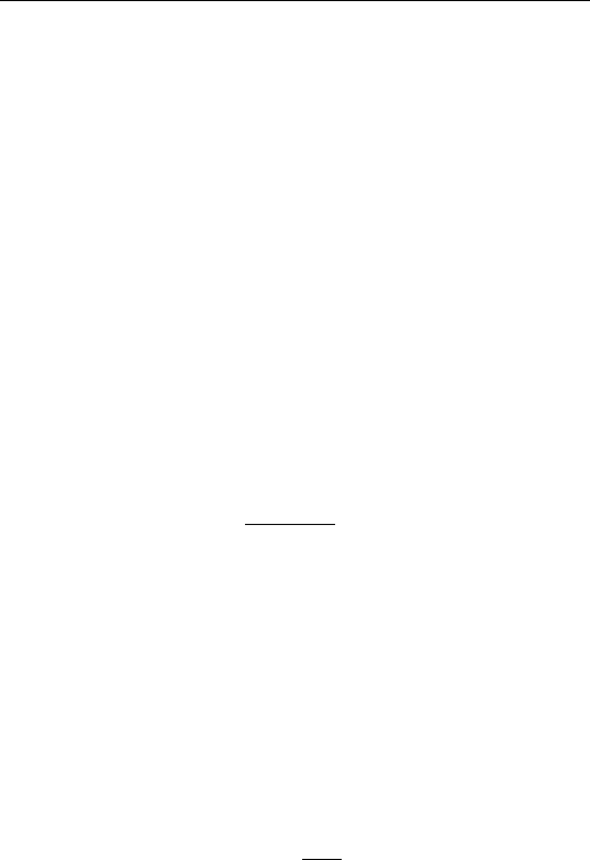
Consider the elastic scattering of an electron at a certain surface
atom site, defined by R
j
(Fig. 5.3). The scattering wave amplitude at
R (observation point) is given by
exp(ik⭈ R)
兩 R 兩
f
j
(k
o
,k)exp[i(k
o
⫺ k)⭈ R
j
] , (5.10)
where k
o
is the wave vector of the incident wave, k that of the scattered
wave, f
j
(k
o
⫺k) the atomic scattering factor (probability amplitude of
scattering electron k
o
to k by an atom at R
j
), and exp[i(k
o
⫺k) ⭈ R
j
] the
phase difference between waves scattered from the origin and R
j
. Since
we consider elastic scattering only, 兩k兩 ⫽ 兩k
o
兩. Therefore, the total
amplitude
tot
due to scattering by all atoms within the coherence width
of the incident electron beam (see later discussion on coherence width)
is given by
tot
⫽ 兺
j
f
j
exp(ik⭈ R)
兩R兩
exp[i(k
o
⫺ k)⭈ R
j
] . (5.11)
For lattices with more than one atom in the basis, that is, more than
one atom associated with one lattice point, we define (from Fig. 5.4)
R
j
⫽ R
l
⫹ R
c
. (5.12)
FIGURE 5.3 Illustration of kinematic scattering of electrons.

90
CHAPTER5/LOW-ENERGY ELECTRON DIFFRACTION
FIGURE 5.4 Position vectors for atoms within the unit cell.
Then it is straightforward to show that
tot
⫽ A兺
c
f
c
exp[i(k
o
⫺ k)⭈ R
c
] ⫻ 兺
l
exp[i(k
o
⫺ k)⭈ R
l
]
(5.13)
⫽ A ⫻ S
G
⫻ G
where S
G
⫽ 兺
c
f
c
exp[i(k
o
⫺ k)⭈ R
c
], the structure factor, and G ⫽
兺
l
exp[i(k
o
⫺ k)⭈ R
l
], the lattice factor.
The total diffraction intensity is given by
兩
tot
兩
2
⫽ A
2
⫻ 兩S
G
兩
2
⫻ 兩G兩
2
(5.14)
This relationship is of general validity for two-dimensional periodic
structures, even in the multiple scattering theory. The only difference
is in S
G
. In the kinematic theory, S
G
is the superposition of atomic
scattering factors weighted by the phase shift, which is only a function
of (k
o
⫺ k). In the multiple scattering theory, S
G
includes multiple and
inelastic scattering, which depend on the individual vectors k
o
and k.
Going back to Eq. (5.14) and considering only the kinematic part
(i.e., the lattice factor G), one notes that the diffraction intensity is
proportional to 兩G
2
兩 ⫽ J, the interference function. Writing R
l
⫽ n
l
a
l
⫹ n
2
a
2
, with n
l
ranging from 0 to M
l
⫺1 and n
2
from0toM
2
⫺ 1,
and ⌬k ⫽ k
o
⫺ k, one can show that
J ⫽
sin
2
M
1
2
(a
→
1
⭈ ⌬ k
→
)
sin
2
1
2
(a
→
1
⭈ ⌬ k
→
)
⫻
sin
2
M
2
2
(a
→
2
⭈ ⌬ k
→
)
sin
2
1
2
(a
→
2
⭈ ⌬ k
→
)
(5.15)

91
5.6 KINEMATIC THEORY
where M
1
and M
2
are the number of unit cells within the electron beam
coherence width in the a
1
and a
2
directions, respectively.
Using the mathematical relation
lim(x → h
)
sin
2
Mx
sin
2
x
⫽ M
2
, (5.16)
we find that J is a maximum (i.e., occurrence of bright diffraction
spots) when
a
1
⭈ ⌬k ⫽ 2h
1
(5.17)
a
2
⭈ ⌬k ⫽ 2h
2
,
where h
1
and h
2
are integers. These are known as the Laue conditions
for constructive interference due to diffraction from 2D lattices.
E
XAMPLE.
Consider two identical 2D domains separated by a
distance vector d. The interference function for one domain is J. Assume
that the electron waves incident on these two domains are coherent so
that the interference function for these two domains is equal to 兩G
1
⫹
G
2
兩
2
,G
i
being the lattice factor for domain i. Show that the interference
function for the combined two domains is given by 2J [1 ⫹ cos (⌬k⭈d)].
S
OLUTION.
Recall that G
i
⫽ 兺
l
exp(i⌬k⭈R
l,i
), where i ⫽ 1, 2. Since
the two domains are separated by distance vector d, we can write R
l,2
⫽ R
1,1
⫹ d. Therefore, the total interference function is given by
冏
兺
l
{exp(i⌬k ⭈ R
l,1
) ⫹ exp[i⌬k ⭈ (R
l,1
⫹ d)]}
冏
2
⫽
冏
兺
l
exp(i⌬k ⭈ R
l,1
) ⫻ [1 ⫹ exp(i⌬k ⭈ d)]}
冏
2
⫽
冏
兺
l
exp(i⌬k ⭈ R
l,1
)
冏
2
⫻ 兩1 ⫹ exp(i⌬k ⭈ d)兩
2
⫽ 2J[1 ⫹ cos(⌬k⭈ d)] .
Q
UESTION FOR
D
ISCUSSION.
In the preceding example, it is as-
sumed that electron waves incident on the two domains are coherent.
How will the solution be different if we assume that the waves incident
on one domain are incoherent with those on the other domain?
92
CHAPTER5/LOW-ENERGY ELECTRON DIFFRACTION
5.7 APPLICATIONS OF THE KINEMATIC THEORY
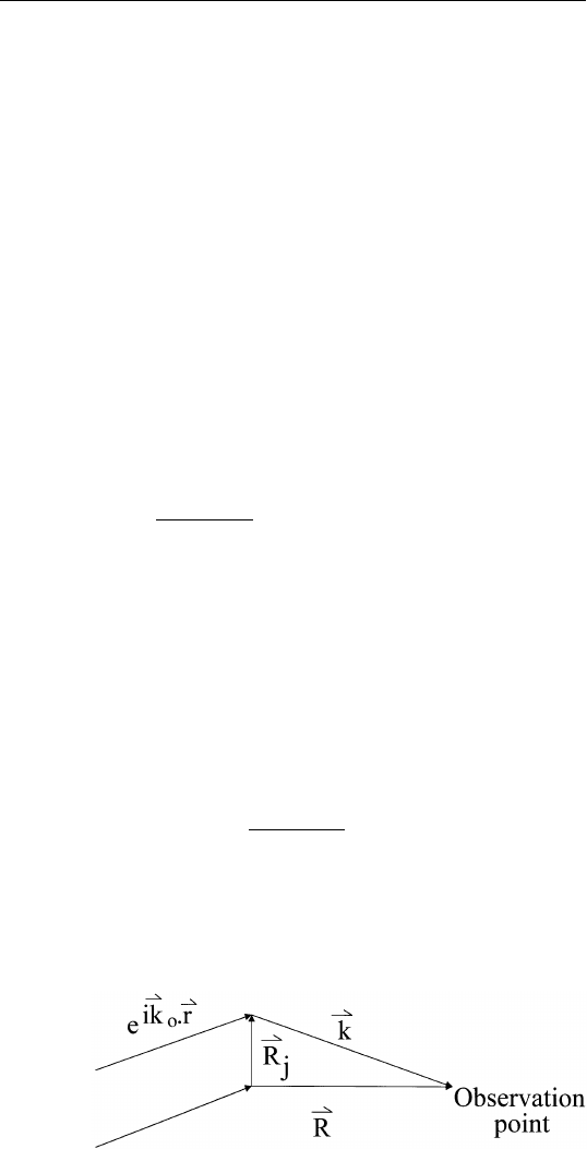
5.7.1 Determination of Real Space Lattice from LEED Pattern
Comparison between Eqs. (5.4) and (5.17) shows that ⌬k’s are recipro-
cal lattice vectors, that is, the diffraction pattern is a direct duplicate
of the reciprocal space. As an example, take the LEED pattern in Fig.
5.5. The filled circles are diffraction spots from the bulk, and the open
circles are diffraction spots from the surface layer. Assume that surface
unit cell is defined by (b
1
, b
2
), whereas the substrate has a structure
defined by (a
1
, a
2
). Then we can write
冉
b
1
b
2
冊
⫽ M
冉
a
1
a
2
冊
.
From Fig. 5.5, we can obtain the matrix M*, as follows
冉
1/2
1/4
0
1/2
冊
.
Since M* ⫽ (M
⫺1
)
T
, we can obtain M from a knowledge of matrices,
given below:
M ⫽
冉
2
0
⫺1
2
冊
.
FIGURE 5.5 Hypothetical diffraction pattern showing spots from substrates (open
circles) and overlayer (filled circles).
93
5.7 APPLICATIONS OF THE KINEMATIC THEORY
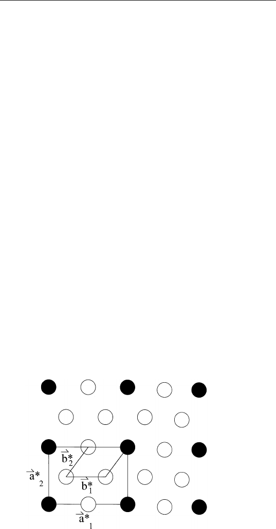
That is,
b
1
⫽ 2a
1
⫺ a
2
b
2
⫽ 2a
2
.
The resulting real space lattice for surface, constructed from the forego-
ing equation, is shown in Fig. 5.6.
5.7.2 Angular Spread of Diffracted Beams
Consider a one-dimensional case. The interference function J is given
by
J ⫽
sin
2
Mx
sin
2
x
(5.18)
where x ⫽
1
–
2
a⭈ ⌬k. J goes to zero when Mx is equal to an integral
multiple of , provided that x is not an integral multiple of . Therefore,
near the maximum of J, the spread of x is on the order of /M (Fig.
5.7). For the scattering geometry shown in Fig. 5.1, the spread dx in
x is related to the angular spread of the diffracted beam d as follows:
dx ⬇ (1/2)ka
1
cos
d
. (5.19)
That is,
d
⬇
Macos
. (5.20)
FIGURE 5.6 Real-space unit cells of substrate and overlayer corresponding to the
diffraction pattern shown in Fig. 5.5.
94
CHAPTER5/LOW-ENERGY ELECTRON DIFFRACTION
FIGURE 5.7 Sketch of the interference function J.
If M is small (small ordered domain), there will be a large angular
spread in the diffracted beam (large diffraction spot). If the size of the
ordered domain is larger in one dimension than the other, one would
observe streaking of the diffraction spot. On the other hand, if M is
large, d will be small. In the limit, when M tends to infinity, d will
be limited by instrumental effects.
Q
UESTION FOR
D
ISCUSSION.
As one increases the electron energy,
the diffraction spots move towards the center of the screen (the (0,0)
beam position). How does the angular width of a given spot change
with electron energy?
Knowing the instrumental broadening, one can in principle use Eq.
(5.20) to deduce the size of ordered domains on surfaces. The ultimate
limitation is the coherence width, the distance over which the electron
waves remain coherent, i.e., having the same phase. The coherence
width L is given by
L ⫽
2

冉
1 ⫹
dE
E
冊
(5.21)
where is the electron wavelength, 2 the total angular divergence,
and dE/E the relative energy spread of incident electrons. Putting in
typical values of ⫽ 0.1 nm, 2 ⫽ 5⫻10
⫺3
rad, and dE/E ⫽ 0.005,
we have L ⫽ 10 nm. Ordered domains of diameters substantially greater
than 10 nm give approximately the same diffraction spot size as those
having diameters ⬇ 10 nm.
95
5.7 APPLICATIONS OF THE KINEMATIC THEORY
5.7.3 Steps
Stepped surfaces are of interest in thin film growth and surface chemis-
try as they are active sites for thin film nucleation and chemical reac-
tions. Stable periodic stepped surfaces can be produced by cutting a
single crystal at small angles from low-index planes, followed by proper
cleaning and annealing treatments. Consider a periodic stepped surface
shown in Fig. 5.8 with the electron beam at normal incidence. Kinematic
analysis shows that the interference function J() is given by
J(
) ⫽
sin
2
冋
1
2
ka(M ⫹ 1)sin
册
sin
2
冉
1
2
kasin
冊
(5.22)
⫻
兺
∞
⫺
∞
␦
冋
1
2
k(Ma ⫹ g)sin
⫹
1
2
kd(1 ⫹ cos
) ⫺ m
册
where M ⫹ 1 is the number of atomic rows on the terrace, a the lattice
spacing, d the step height, g the horizontal step displacement, k the
electron wave vector (⫽2/), and the diffraction angle. The first
term is the interference function of a periodic array of (M ⫹ 1) atoms
and attains a maximum when
1
–
2
ka sin ⫽ n. The second term consists
of a sum of delta functions, which are nonzero only when their argu-
ments are equal to zero. This term gives rise to splitting of the diffraction
spot. From Eq. (5.22), the angular separation between two split spots
is
⌬
⫽
(Ma ⫹ g)cos
⫺ dsin
. (5.23)
FIGURE 5.8
Diffraction from a stepped surface.

96
CHAPTER5/LOW-ENERGY ELECTRON DIFFRACTION
For the (0,0) spot, ⫽ 0 so that ⌬ ⫽ /W, where W ⫽ Ma ⫹ g, the
terrace width. Therefore, measurement of the splitting gives directly
the terrace width. Further, from Eq. (5.22), one notes that the spots are
not split at certain electron wavelengths. For the (0,0) spot, this occurs
when 2d ⫽ n, where n is an integer.
Q
UESTION FOR
D
ISCUSSION.
Real surfaces consist of steps and
terraces so that one would expect to see splitting of diffraction spots.
However, assuming that the splitting is not too large, the splitting will
appear as broadening of the diffraction spot. With this assumption,
discuss how the angular width of a diffraction spot from a surface with
steps and terraces varies with electron energy.
5.7.4 Surface Vibrations
At any one instant, many of the surface atoms are displaced from their
equilibrium positions because of surface vibrations. Thus, the incident
electron beam in LEED experiments encounters a partially disordered
surface. The atoms that are displaced from their equilibrium positions
during the scattering process will scatter out of phase. A fraction of
the elastically scattered electrons will be found in the background
instead of the diffraction spot. The larger the vibration amplitude, the
more likely that the backscattered electrons will be in the background
instead of contributing to the diffraction.
In the appendix, it is shown that the intensity of a given diffraction
spot as determined by ⌬k decreases with increasing surface temperature
as
I ⫽ I
o
exp
冋
⫺
3(⌬k)
2
ប
2
T
mk
B
2
D
册
, (5.24)
where
D
is the surface Debye temperature. For the (0,0) spot near
normal incidence,
I ⫽ I
o
exp
冉
⫺
12
ប
2
k
2
T
mk
B
2
D
冊
. (5.25)
Therefore, measurement of diffraction intensity as a function of temper-
ature gives the surface Debye temperature, which is inversely propor-
tional to the r.m.s. displacement perpendicular to the surface, averaged
over the sampling depth of the electron beam. Experiments show that