Chilingarian G.V. et al. Surface Operations in Petroleum Production, II
Подождите немного. Документ загружается.

385
be provided to minimize displacement of the tower during severe storm conditions
and to limit the motions during platform operation in calmer weather.
The tower platform has multiple well capability, with each production string
being contained within a conductor and supported by a bowl at the base near the
ocean floor. As a result, tower platforms do not experience any vertical stress. At
the top, bottom, and the intermediate regions, the conductors are laterally sup-
ported by guides to hold them in the desired vertical position and minimize bending
as the tower sways. This gives rise to horizontal stress components that add to the
overturning moment. Well casings are permitted to bend elastically with the swaying
of the tower. The base of the structure is secured to the seafloor by piles. In order to
counter the huge uplift force provided by the buoyancy tanks, a ballast tank is
employed. It serves an additional purpose of providing buoyancy to support the
lower end of the tower during tow-out.
The tower-type platform has the following advantages:
(1)
launch barge
is
not
required, (2) liquid storage is possible in its large legs, and
(3)
the platform has
fewer braces and relatively larger members. These large members are more ice-re-
sistant, which is advantageous in ice environments.
There are, however, the inherent disadvantages of: (1) increased towing time,
usually about twice that for the jacket platform; this is important to consider for
long distance tows,
(2)
higher steel requirements for a given depth because internal
bracings, etc. are required,
(3)
lack of redundancy, i.e., the whole structure collapses
due to the failure of even a single critical member, and
(4)
the need for a dry dock
or launchway.
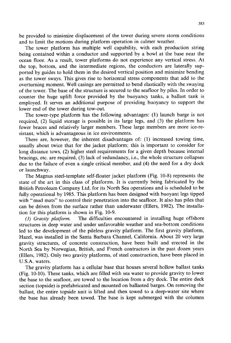
The Magnus steel-template self-floater jacket platform (Fig. 10-8) represents the
state of the art in this class of platforms. It is currently being fabricated by the
British Petroleum Company Ltd. for its North Sea operations and is scheduled to be
fully operational by 1985.
This
platform has been designed with buoyant legs tipped
with “mud mats” to control their penetration into the seafloor. It also has piles that
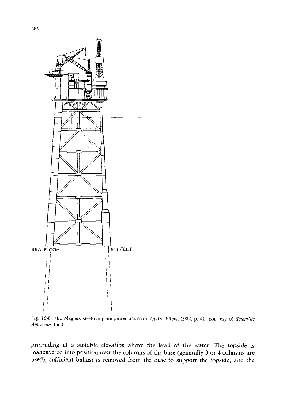
can be driven from the surface rather than underwater (Ellers, 1982). The installa-
tion for this platform is shown in Fig. 10-9.
The difficulties encountered in installing huge offshore
structures in deep water and under unfavorable weather and sea-bottom conditions
led to the development of the pileless gravity platform. The first gravity platform,
Hazel, was installed in the Santa Barbara Channel, California. About 20 very large
gravity structures, of concrete construction, have been built and erected in the
North Sea by Norwegian, British, and French contractors in the past dozen years
(Ellers, 1982). Only two gravity platforms, of steel construction, have been placed in
U.S.A. waters.
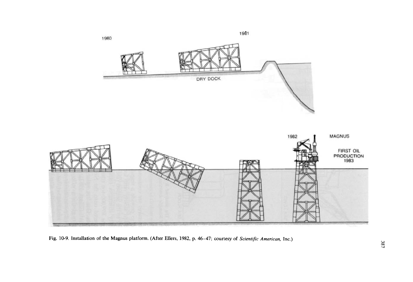
The gravity platform has a cellular base that houses several hollow ballast tanks
(Fig.
10-10).
These tanks, which are filled with sea water to provide gravity to lower
the base to the seafloor, are towed to the location from a dry dock. The entire deck
section (topside) is prefabricated and mounted on ballasted barges. On removing the
ballast, the entire topside unit is lifted and then towed to a deep-water site where
the base has already been towed. The base is kept submerged with the columns
(3)
Gruoity
platform.
386
T
I1
II
II
Fig.
10-8.
The Magnus steel-template jacket platform.
American,
Inc.)
(After Ellers,
1982,
p.
41;
courtesy
of
Scientific
protruding at a suitable elevation above the level of the water. The topside is
maneuvered into position over the columns of the base (generally
3
or 4 columns are
used), sufficient ballast is removed from the base to support the topside, and the
1981
1980
FIRST
OIL
PRODUCTION
Fig.
10-9.
Installation of the Magnus platform. (After Ellers,
1982,
p.
46-47;
courtesy of
Screntrfc Amerrcan,
Inc.)
W
4
m
388
SEA
FLOOR
472
FEE?
Fig.
10-10.
The Statfjord
B
gravity-concrete platform in the North Sea. (After Ellers,
1982,
p.
40;
courtesy of
Scientific American,
Inc.)
two structures are connected with heavy steel rods. These rods are tensioned and
grouted to provide a singular structure. The finished gravity platform structure
is
then towed slowly onto location, where the base is again ballasted to lower the
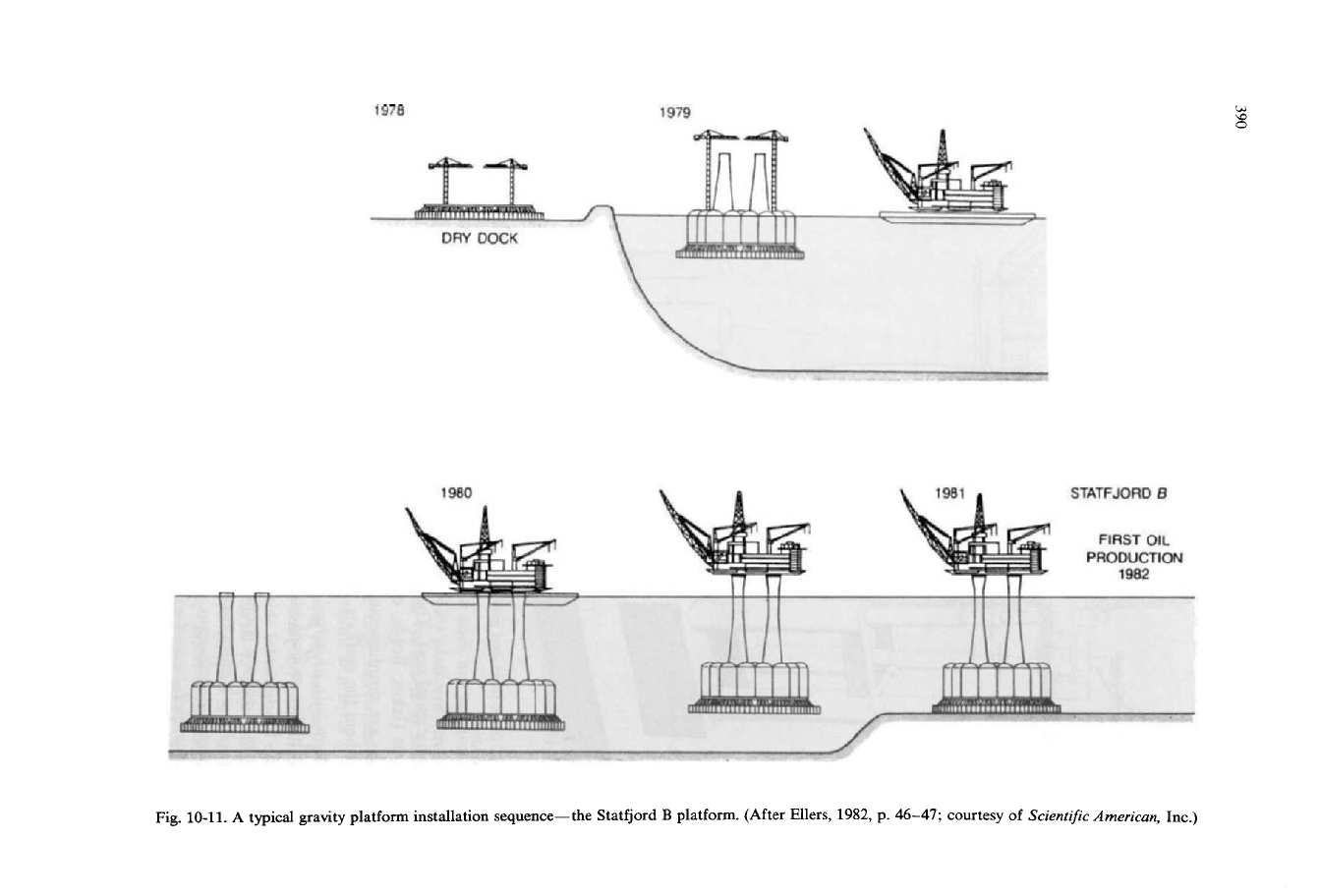
structure to the seabed (see Fig. 10-11).
Gravity structures require a firm seafloor to support their enormous weight.
When the 899,000-ton (the world’s heaviest platform) Statfjord
B
gravity platform
was lowered onto the North Sea floor, it released the water in the underlying
sediments. This free water had to be drained out by drilling shallow wells from the
utility shaft (Ellers, 1982).
Gravity platforms offer an enormous storage capacity, which is a big advantage
if
pipelines are unavailable and tankers are the means of transporting the oil onshore.
Another advantage is that, in principle, they can be almost immediately made ready
for drilling activities after being towed out and installed. The biggest disadvantage is
389
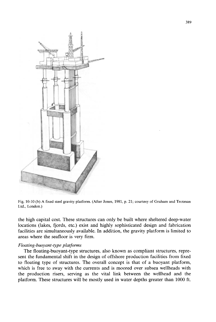
Fig.
10-10
(b)
A fixed steel gravity platform. (After Jones,
1981,
p.
21;
courtesy
of
Graham and Trotman
Ltd., London.)
the high capital cost. These structures can only be built where sheltered deep-water
locations (lakes, fjords, etc.) exist and highly sophisticated design and fabrication
facilities are simultaneously available. In addition, the gravity platform is limited to
areas where the seafloor is very firm.
Flouting-buoyant-type platforms
The floating-buoyant-type structures, also known as compliant structures, repre-
sent the fundamental shift in the design of offshore production facilities from fixed
to floating type of structures. The overall concept
is
that of a buoyant platform,
which
is
free to sway with the currents and is moored over subsea wellheads with
the production risers, serving as the vital link between the wellhead and the
platform. These structures will be mostly used in water depths greater than
1000
ft.
1978
1979
1980
STATFJORD
B
FIRST
OIL
PRODUCTION
1982
W
Fig.
10-11.
A
typical gravity platform installation sequence-the Statfjord
B
platform. (After Ellers, 1982, p.
46-47;
courtesy
of
Scientific
American,
Inc.)
391
The two types of feasible buoyant structures are: (1) the guyed tower, and (2) the
tension-leg platform. Semisubmersibles can also be converted into production
platforms; however, they are very sensitive to topside loading. This is as well true of
the other buoyant-type structures to some extent. The latter, however, are generally
larger and rest on the seafloor, which provides additional support, and therefore,
can support the required production facilities.
The guyed tower is a slender-trussed structure that rests on the
seafloor, with guylines holding the structure in place. The tower transmits the
primarily vertical gravity loads imposed by the drilling and production equipment
mounted on the surface decks to the seafloor. There are two ways of providing
support for the tower at the seafloor. One is by the conventional piled foundation.
The second means of anchoring the guyed tower is by pure gravity: the base is
implanted in the seafloor using a vertical bearing foundation consisting of a
truss-reinforced stiffened shell called the “spud can”. In the latter case, long-term
settling of the tower can be a problem. This is avoided by preloading the structure
during installation. In the final stages of tower installation when the tower has been
installed in an upright position, the spud can is artificially forced into the ocean
bottom until the desired load-carrying capability is reached. Drilling mud is pumped
into the spud can in order to achieve this purpose; thereafter, the mud is pumped
out. The well conductors penetrate through the spud can.
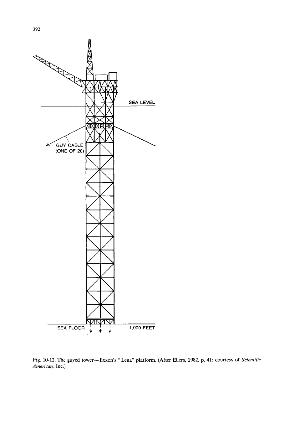
The guyed tower (Fig. 10-12) is a relatively simple structure and is not difficult to
fabricate. It is not very heavy and its movement (sway) is within satisfactory limits.
Horizontal support for the guyed tower is provided by 12-24 wire-rope, synthetic
material, or chain-type cables called guylines (Dunn, 1980). These guylines are
secured on one end to the bridge strands arranged symmetrically around the tower
by means of pairs of wedge-type Lucker clamps. The guylines run downward from
these bridge strands to the fairleads kept about
50
ft below the mean water level
so
that they are below the keel of passing vessels. Through these fairleads, the guylines
run further on to clump weights on the seafloor. Beyond the clump weights, the
guylines run to either anchor piles or to conventional drag anchors.
The cable tension is controlled through the Lucker clamps and a hydraulic
jacking system. The tower is designed to give a maximum tilt of
2”
or less during
expected storm conditions. In moderate seas, the clump weights remain on the
seafloor and keep the guylines in a taut condition. Under extreme storm conditions,
the design-allowable tower oscillations may be exceeded, and once they become too
large, the clumps will gradually lift
off
the seafloor, softening the guying system and
further endangering the structure.
The guyed tower is simpler and cheaper to construct and requires only conven-
tional fabrication equipment and techniques. Its installation, however, is quite
sophisticated and complex, particularly with respect to the guylines, clumps, and
anchor piles (Anonymous, 1981). The guyed tower also is relatively cost-insensitive
to increased water depth. There are, however, some cost increases with depth:
mooring costs and maintenance costs increase with water depth and remoteness.
Fig. 10-13 shows the installation of the guyed tower-type Lena platform in the
(1)
Guyed
tower.
392
SEA
FLOOR
1.000
FEET
Fig.
10-12. The guyed tower-Exxon’s “Lena” platform.
American,
Inc.)
(After Ellers,
1982,
p.
41;
courtesy
of
Scientific
393
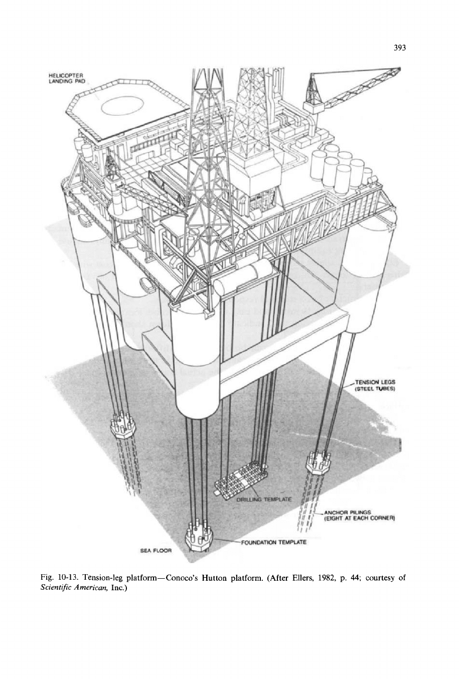
Fig.
10-13.
Tension-leg platform-Conoco’s Hutton platform. (After Ellers, 1982, p.
44;
courtesy
of
Scientific
American,
Inc.)
394
Gulf of Mexico. This platform, which is being built for Exxon by Brown and Root
Inc. will stand in about a
1000
ft of water and will be the first such structure.
Production activities were proposed to begin in 1984. Exxon has already tested a
prototype in
250
ft of water.
As
is evident from Fig. 10-13, the guyed tower is launched sideways instead of
lengthwise into the ocean. It is then upended, placed on bottom, and the guylines
are installed. The tower structure is designed to be self-floating.
The tension-leg platform (TLP) consists
of
a buoyant,
semisubmersible, triangular- or rectangular-shaped structure held in-place by verti-
cal tension cables attached to the dead-weight anchors. The desired buoyancy is
provided by submerged flotation cylinders designed to minimize the effects of
weather and wave conditions. The subsea wellhead system is connected through
risers to the structure. The TLP has the following advantages:
(1) Favorable motion response and stability characteristics: there is not much
need to compensate for normal floating conditions offshore. This permits the use of
land-type drilling equipment and surface completions.
(2)
The cost is almost independent of depth, the only incremental cost with depth
being that of longer tension-leg cables. Thus, it offers distinct cost advantages in
deep waters.
(2)
Tension-leg
platform.
(3)
The structure has a minimal response to earthquakes.
(4) The TLP is easy to install and easy to move to another location; for example,
in
a case where delineation wells indicate that the platform should be located in
a
different position.
(5)
The same basic platform can be outfitted for different applications. Field
development time is also reduced, because it is possible to fabricate the platform
before field discovery, i.e., before knowing the actual water depth and other design
criteria.
(6)
It is possible to complete the wells either at the ocean bottom or on the
surface.
(7)
The TLP offers a larger overall production capacity as compared to conven-
tional floating production platforms.
The TLP has two main structural elements: (a) the floating hull, which is similar
to
a semisubmersible drilling rig but is much larger, and (b) the vertical array of
highly-tensioned tethers at each corner. The floating hull is designed with a careful
balance between the buoyancy and the freeboard (the part of the hull above water)
in order to handle extreme troughs as well as crests (Ellers, 1982). The tethers
or
cables, made either of high tensile-strength steel tubes or wire ropes, are designed to
hold the floating hull down with a tension such that they do not become slack even
in the trough of the maximum wave expected (usually, this is taken
to
be the
maximum wave expected to occur once every hundred years). The platform remains
virtually horizontal under wave action. The lateral excursions are controlled by the
design of the tethers.
To
anchor the system to the seabed, either piled templates or
gravity units can be used (similar to the guyed tower).
The offshore industry has exhibited a great interest in the TLP. Designs have