Cao Z. (Ed.) Thin Film Growth: Physics, materials science and applications
Подождите немного. Документ загружается.

388 Thin film growth
© Woodhead Publishing Limited, 2011
smooth surfaces with small b values. At higher sticking coefcient values,
the shadowing effect becomes the dominant process and columnar rough
morphologies start to form. On the other hand, like in experiments, it was
not possible to capture a ‘universal’ growth behavior using Monte Carlo
simulation approaches, which would lead to dynamically common aspects
of various thin lm growth processes.
Moreover, it has very recently been revealed that shadowing effect can
lead to the breakdown of dynamical scaling theory due to the formation
of a mounded surface morphology [16, 17]. In these studies, using Monte
Carlo simulations it has been shown that for common thin lm deposition
techniques, such as sputter deposition and CVD, a ‘mound’ structure can be
formed with a characteristic length scale that describes the separation of the
mounds, or ‘wavelength’ l. It has been found that the temporal evolution of
l is distinctly different from that of the mound size, or the lateral correlation
length, x. The formation of the mound structure is due to non-local growth
effects, such as shadowing, that lead to the breakdown of the self-afnity of
the morphology described by the dynamic scaling theory. The wavelength
T
s
= 100 K
T
s
= 100 K
Cu on H
2
O/SiO
2
Ti
W
Cu
Nb
TaN
Zr
Ta
Ta
Bi (T
s
~900 –1000 K)
No substrate heating
(except Bi)
200 K
300 K
400 K
700 K
500 K
600 K
Cu on SiO
2
Li
Cu
T
s
~300–550 K
T
s
~300–650 K
Si
2
H
6
SiH
3
SiH
2
Evaporation Sputtering CVD
Deposition method
Sticking coefficient, s
1.0
0.9
0.8
0.7
0.6
0.5
0.4
0.3
0.2
0.1
0.0
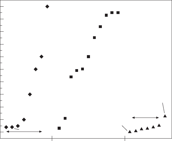
16.3 Some of the experimentally measured sticking coefficient values
reported in the literature during evaporation [23], sputtering [24–31],
and CVD [32–38] growth. Names of incident atoms/molecules on the
growing film are also labeled. In same cases, depositions were done
with substrate heating at temperatures denoted as T
s
in the figure.
ThinFilm-Zexian-16.indd 388 7/1/11 9:46:39 AM
389Network behavior in thin films & nanostructure growth dynamics
© Woodhead Publishing Limited, 2011
grows as a function of time in a power law form, l ~ t
p
, where p ª 0.5 for
a wide range of growth conditions, while the mound size grows as x ~ t
1/z
,
where 1/z depends on the growth conditions.
In brief, conventional growth models in dynamic scaling theory cannot
explain most of the experimental results reported for dynamic thin lm
growth; and dynamic scaling theory itself often suffers from a breakdown
if shadowing effect is present, which is the case for most of the commonly
used deposition techniques. On the other hand, simulation techniques
were not successful in revealing the possible universal behavior in various
growth processes. Furthermore, simulations that can successfully predict
the experimental results cannot always be easily implemented by other
researchers. Therefore, there is an immense need for alternative and robust
modeling approaches for the dynamical growth of thin lm surfaces that
incorporates easy-to-implement analytical and/or empirical relations which
in turn can lead to universal growth behavior aspects of thin lms. In this
work, we explore a radically new ‘network’ modeling approach for the
dynamical growth of a large variety of thin lm growth systems that can
potentially capture universal properties of lm growth processes and at the
same time not suffer from the shortcomings of dynamic scaling theory and
Monte carlo simulation approaches mentioned above.
Monte Carlo simulated
CVD growth
s = 0.1, no diffusion
s = 1, no diffusion
Rough
No diffusion
D/F = 20
D/F = 50
Smooth
0.1 0.2 0.3 0.4 0.5 0.6 0.7 0.8 0.9 1.0
Sticking coefficient, s
Growth exponent, b
1.0
0.8
0.6
0.4
0.2
0.0
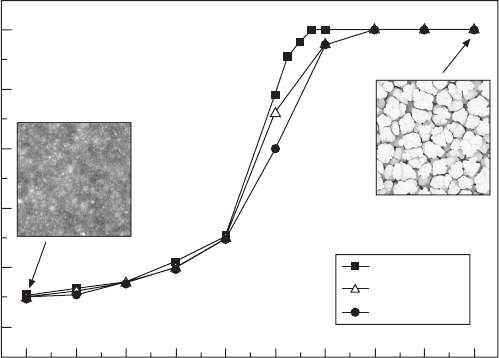
16.4 Growth exponent b values for a Monte Carlo simulated chemical
vapor deposition (CVD) growth obtained for various first-impact
sticking coefficient (s) and surface diffusion (D/F) values. The sticking
coefficient at the second impact after re-emission was set to 1. Two
sample surface morphologies are also included for a small s = 0.1
(left) and high s = 1 (right) sticking coefficient value, which leads to a
smooth and rough surface topography, respectively.
ThinFilm-Zexian-16.indd 389 7/1/11 9:46:40 AM
390 Thin film growth
© Woodhead Publishing Limited, 2011
Network modeling pervades various areas of science ranging from
sociology to statistical physics or computer science, see ref. [43] and the
references therein. A network in terms of modeling can be dened as a set
of items, referred to as nodes with links connecting them. Examples of real-
life complex networks include the Internet, the World Wide Web, metabolic
networks, transportation networks, social networks, etc. recent studies show
that many of these networks share common properties such as having a low
degree of separation among the nodes (modeled as small-world networks
[44]), having a power-law degree/connectivity distributions (modeled as
scale-free networks [45]), etc.
16.2 Origins of network behavior during thin film
growth
Interestingly, non-local interactions among the surface points of a growing
thin lm that originate from shadowing and re-emission effects (Fig. 16.2)
can lead to non-random preferred trajectories of atoms/molecules before they
nally stick and get deposited. For example, during re-emission, the path
between two surface points where a particle bounces off from the rst and
heads on to the second can dene a ‘network link’ between the two. If the
sticking coefcient is small, then the particle can go through multiple re-
emissions that form links among many more other surface points. In addition,
due to the shadowing effect, higher surface points act as the locations of
rst-capture and centers for re-emitting the particles to other places. In this
manner, hills on a growing lm resemble the network ‘nodes’ of heavy trafc,
where the trafc is composed of the amount of particles re-emitting from the
nodes. In terms of network trafc, nodes can be classied as: source, sink,
or router. So, the initial point/hill where an atom re-emits can correspond to
a ‘source’ in a network, and the nal point where the atom sticks/settles can
be thought as a ‘sink’ in the network. Similarly, the intermediate re-emission
points/hills can be thought as the ‘routers’. Therefore, a ‘trafc model’ for
thin lm growth can then be constructed by counting the number of atoms
starting from a point on the lm and ending at another point on the lm.
16.3 Monte Carlo simulations
Development of network models by our approach requires the track record
of the trajectories of re-emitted and deposited atoms/particles. Since it is not
possible to experimentally track the trajectories of re-emitted and deposited
atoms during dynamic thin lm growth, we used 3D Monte Carlo simulation
approaches instead, which were already shown to efciently mimic the
experimental processes and predict the correct dynamical growth morphology
[9, 10, 16, 17, 21, 22, 40, 41]. In these simulations, each incident particle
ThinFilm-Zexian-16.indd 390 7/1/11 9:46:40 AM
391Network behavior in thin films & nanostructure growth dynamics
© Woodhead Publishing Limited, 2011
(atom/molecule) is represented with the dimension of one lattice point. As
substrate, we used a N ¥ N = 512 ¥ 512 size lattice with continuous boundary
conditions. A specic angular distribution for the incident ux of particles
is chosen depending on the deposition technique being simulated. During
normal angle deposition, all the particles are sent from the top along the
substrate normal (polar angle q = 0°), while during oblique angle deposition
simulations we used a grazing incidence ux where all particles are emitted
at an angle of q = 85° from the substrate normal. For CVD, the incident ux
had an angular spread according to the distribution function dP(q, f)/dW =
cos q/p, where f is the azimuthal angle [39].
At each simulation step, a particle is sent toward a randomly chosen
lattice point on the substrate surface. Depending on the value of sticking
coefcient (s), the particle can bounce off and re-emit to other surface points.
Re-emission direction is chosen according to a cosine distribution centered
around the local surface normal [39]. At each impact, sticking coefcient
can have different values represented as s
n
, where n is the order of re-
emission (n = 0 being for the rst impact). In this study, we use a constant
sticking coefcient value for all impacts (i.e. s
n
= s for all n) during a given
simulation, which is a process also called ‘all-order re-emission’ [39]. In all
the emission and re-emission processes, shadowing effect is included, where
the particle’s trajectory can be cut off by long surface features on its way to
other surface points. After the incident particle is deposited onto the surface,
it becomes a so-called ‘adatom’. Adatoms can hop on the surface according
to some rules of energy, which is a process mimicking the surface diffusion.
However, as noted before, non-local processes of re-emission and shadowing
are generally dominant over local surface diffusion effects. Therefore, in this
work we did not include surface diffusion in order to better distinguish the
effects of re-emission and shadowing effects. After this deposition process,
another particle is sent, and the re-emission and deposition are repeated in
a similar way.
In our simulations, deposition time t is represented by number of particles
sent to the surface. Final simulation time (total number of particles sent) for all
the simulations was t
nal
= 25 ¥ 10
7
. Because of re-emission, deposition rate
and therefore average lm thickness (d) depended on the sticking coefcient
s used, and changed with simulation time t approximately according to d ª
t ¥ s/(N ¥ N), where lattice size N was 512.
Furthermore, in our simulations, trajectories of particles during each
re-emission process can be tracked in order to reveal the dynamic network
behavior in detail. When the simulation time reaches a pre-set value that
we called the ‘snapshot state’, we label each particle sent to the surface and
start recording the coordinates of lattice point where the particle impacts
and also the lattice point where it is re-emitted and makes another impact.
Therefore, especially a small sticking coefcient particle can potentially
ThinFilm-Zexian-16.indd 391 7/1/11 9:46:40 AM
392 Thin film growth
© Woodhead Publishing Limited, 2011
make multiple re-emissions among the surface points and have multiple
trajectory data. In order to increase the number of trajectory data for a better
statistical analysis while keeping the surface morphology unchanged, we
cancelled the nal deposition of the particle sent during the trajectory data
collection process. In other words, when the simulation time reached the
pre-set value, particles were still being sent for re-emission and collection of
trajectory data; however, they were not depositing to the surface, therefore
not changing the surface morphology. We collected the trajectory data of
about 10
6
re-emitted particles for each snapshot state. We did not include
the trajectory data of particles as they re-emitted into the space or if they
crossed the lattice boundaries, since cross-boundary particles can lead to
articially long trajectories due to the continuous boundary conditions used.
All the simulation results are an average of 10 runs (realizations), each time
using a different seed number for the random number generator.
16.4 Results and discussion
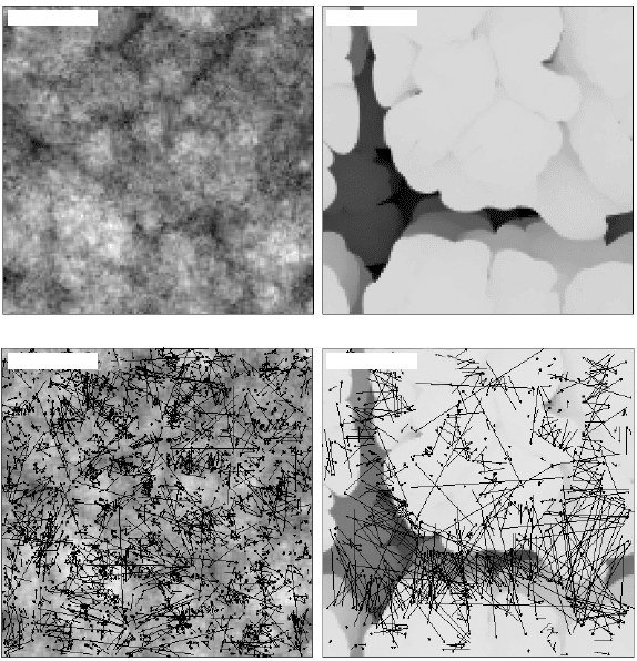
Figure 16.5 shows the snapshot top view images of two surfaces simulated
for a CVD type of deposition, at two different sticking coefcients. Figure
16.5 also displays their corresponding particle trajectories projected on
the lateral plane. Qualitative network behavior can easily be realized in
these simulated morphologies as the trajectories of re-emitted atoms ‘link’
various surface points. It can also be seen that larger sticking coefcients
(Fig. 16.5(b) and (d)) lead to fewer but longer range re-emissions, which
are mainly among the peaks of columnar structures. Therefore, these higher
surface points act as the ‘nodes’ of the system. This is due to the shadowing
effect where initial particles preferentially head to hills. They also have less
chance to arrive down to valleys because of the high sticking probabilities
(see for example particle A illustrated in Fig. 16.2). On the other hand, at
lower sticking coefcients (Fig. 16.5(a) and (c)), particles now go through
multiple re-emissions and can link many more surface points including the
valleys that are normally shadowed by higher surface points (particle b
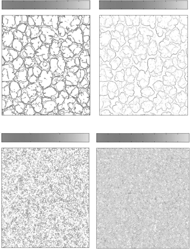
in Fig. 16.2). This behavior is better realized in ‘surface-degree’ and their
corresponding height matrix plots of Fig. 16.6 measured for CVD grown lms
at two different sticking coefcients s = 0.1 and s = 0.9. The high values
(darker shades) in surface-degree plots correspond to the highly connected
surface sites where these sites get or re-distribute most of the re-emitted
particles. At smaller sticking coefcients (Fig. 16.6(a)), which lead to a
smoother morphology, surface-degree values are quite uniform indicating
a uniform re-emission process among hill-to-hills and hill-to-valleys. On
the other hand, at high sticking coefcients (Fig. 16.6(b)), the high degree
nodes are mainly located around the column borders suggesting a dominant
column-to-column re-emission. This is consistent with the shadowing effect
ThinFilm-Zexian-16.indd 392 7/1/11 9:46:40 AM
393Network behavior in thin films & nanostructure growth dynamics
© Woodhead Publishing Limited, 2011
where columns capture most of the incident particles because of their larger
heights, and also their borders are more likely to re-distribute the particles
towards the neighboring column sides because of the re-emission process
used (i.e. cosine distribution centered along the local surface normal).
Another interesting observation revealed in our Monte carlo simulations
was the dynamic change of network behavior on the trajectories of re-emitted
particles. Figure 16.7 shows top view images and their corresponding particle
trajectories obtained from the CVD simulations for a sticking coefcient of
(a) s = 0.1
(c) s = 0.1
(b) s = 0.9
(d) s = 0.9
16.5 Top view images from Monte Carlo simulated thin film surfaces
grown under shadowing, re-emission, and noise effects (no surface
diffusion is included in these simulations) for sticking coefficients
(a) s = 0.1 and (b) s = 0.9 and with unity sticking coefficient at
the second impacts. Each image corresponds to a 128 ¥ 128
portion of the total lattice. The incident flux of particles has an
angular distribution designed for chemical vapor deposition (CVD).
Corresponding projected trajectories of the re-emitted particles are
also mapped on the top view morphologies for (c) s = 0.1 and (d) s =
0.9. Qualitative network behavior can be seen among surface points
linked by the re-emission trajectories.
ThinFilm-Zexian-16.indd 393 7/1/11 9:46:40 AM
© Woodhead Publishing Limited, 2011
Height (i,j)
Degree (i,j)
500
450
400
350
300
250
200
150
100
50
500
450
400
350
300
250
200
150
100
50
500
450
400
350
300
250
200
150
100
50
500
450
400
350
300
250
200
150
100
50
130
125
120
115
18
16
14
12
10
8
6
4
2
100 200 300 400 500
100 200 300 400 500
(a) CVD s = 0.1
100 200 300 400 500
100 200 300 400 500
(b) CVD s = 0.9
900
800
700
600
500
400
300
200
100
90
80
70
60
50
40
30
20
10
16.6 Height matrix
and corresponding
surface-degree
values are plotted
for CVD grown
films with sticking
coefficients (a) s =
0.1 and (b) s = 0.9.
Total lattice size
is 512 ¥ 512 and
simulation time
for these snapshot
states was t = 23.75
¥ 10
7
particles.
ThinFilm-Zexian-16.indd 394 7/1/11 9:46:40 AM
© Woodhead Publishing Limited, 2011
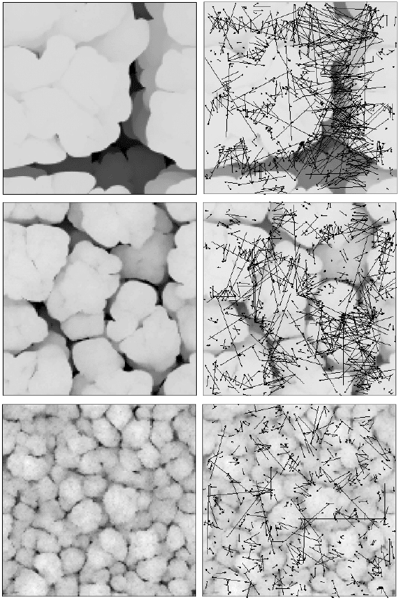
d = 71 lattice units d = 359 lattice units d = 1754 lattice units
Top view morphologies at different
film thicknesses (d)
Trajectories of non-sticking
re-emitted particles
16.7 First row: Top view images from Monte Carlo simulated thin film surfaces for a CVD growth with s = 0.9 at different
film thicknesses d, which is proportional to growth time. Bottom row: Corresponding projected trajectories of the re-
emitted particles qualitatively show the dynamic change in the network topography.
ThinFilm-Zexian-16.indd 395 7/1/11 9:46:40 AM
396 Thin film growth
© Woodhead Publishing Limited, 2011
s
= 0.9, but this time at different lm thicknesses proportional to the growth
time. The dynamic change in the network topography can be clearly seen:
at initial times, when the hills are smaller and more closely spaced, the re-
emitted particles travel from one hill to another one or to a valley. However,
as the lm gets thicker, and some hills become higher than the ossthers and
get more separated, particles travel longer ranges typically among these
growing hills. The shorter hills that get shadowed become the valleys of the
system.
It is expected that this dynamic behavior should be strongly dependent
on the values of sticking coefcients and angular distribution of the incident
ux of particles, which determine the strength of re-emission and shadowing
effects, respectively. In other words, each deposition technique and material
system can have different dynamic network behavior that can lead to various
kinds of network systems. For example, as we will show later, the dynamic
network among the surface points of a mounded CVD grown lm can be
quite different from the one among the nanorod and nanospring structures
formed in an oblique angle deposition system, where the shadowing effect
is most dominant, and also the one during normal angle evaporation, where
the shadowing effect is almost absent (re-emitted particles during normal
angle deposition can still lead to a minimal short-range shadowing effect).
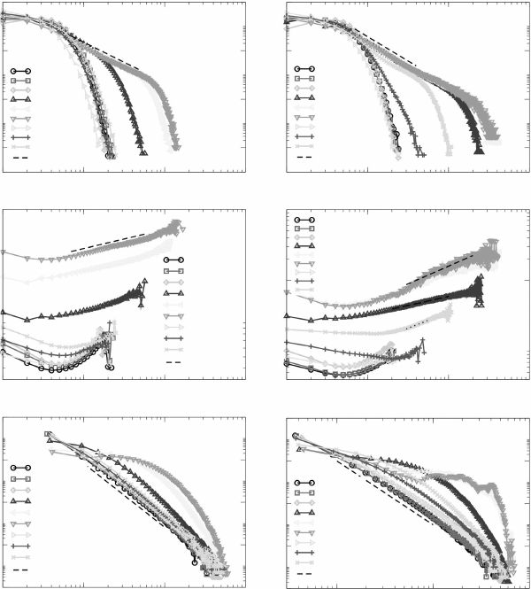
In order to make a more quantitative analysis of the network characteristics
of thin lm growth dynamics, in Fig. 16.8, we plotted the degree distributions
P(k) (i.e. proportional to the percentage of surface points having ‘degree
(k)’ number of links through incoming or outgoing re-emitted particles),
average distance <l
k
> versus degree k (i.e. the average ‘lateral’ distance
particles travel that are re-emitted from/to surface sites having k number of
links), and distance distributions P(l) (i.e. proportional to the probability of
a re-emitted particle traveling lateral distance l) for Monte carlo simulated
normal incidence evaporation, oblique angle deposition, and CVD thin lm
growth for various sticking coefcients. The left and right columns in Fig.
16.8 correspond to the initial (thinner lms) and later (thick lms) stages of
the growth times, respectively. First, the comparison of degree distributions
(Fig. 16.8(a) and (b)) of normal incidence and oblique angle growth reveals
that independent of most sticking coefcients used and also their growth
time, universal behavior exists for both deposition techniques. There is an
exponential degree distribution for normal angle evaporation (conrmed in
the semi-log plots, not shown here), while this behavior is mainly power-
law for oblique angle deposition with an exponential tail. Interestingly,
quantitative values of degree distributions for both normal and oblique angle
depositions also seem to be independent of the sticking coefcient used, which
becomes clearer at later stages of the growth (Fig. 16.8(b)), leading to two
distinct distributions for each deposition. The power-law observed in degree
distribution of oblique angle deposition has a P(k) ~ k
–2
behavior apparent
ThinFilm-Zexian-16.indd 396 7/1/11 9:46:41 AM
397Network behavior in thin films & nanostructure growth dynamics
© Woodhead Publishing Limited, 2011
at later stages. All these suggest the possibility of a universal behavior in
normal and oblique angle growth independent of the sticking coefcient.
This is quite striking since each different sticking coefcient corresponds to
a different type of morphological growth (i.e., smoother surfaces for smaller
sticking coefcients and rougher surfaces for higher sticking coefcients),
yet the degree distribution in network trafc of re-emitted particles seems
to reach a unique universal state.
P(k)P (l)
P (l)
P(k)
10
0
10
–2
10
–4
10
–6
10
0
10
–2
10
–4
10
–6
10
–8
10
0
10
–2
10
–4
10
–6
10
–8
10
0
10
–2
10
–4
10
–6
A0, s = 0.1
A0, s = 0.5
A0, s = 0.9
A85, s = 0.1
A85, s = 0.5
A85, s = 0.9
CVD, s = 0.1
CVD, s = 0.5
CVD, s = 0.9
k
–1.65
A0, s = 0.1
A0, s = 0.5
A0, s = 0.9
A85, s = 0.1
A85, s = 0.5
A85, s = 0.9
CVD, s = 0.1
CVD, s = 0.5
CVD, s = 0.9
k
–0.17
A0, s = 0.1
A0, s = 0.5
A0, s = 0.9
A85, s = 0.1
A85, s = 0.5
A85, s = 0.9
CVD, s = 0.1
CVD, s = 0.5
CVD, s = 0.9
l
–3
A0, s = 0.1
A0, s = 0.5
A0, s = 0.9
A85, s = 0.1
A85, s = 0.5
A85, s = 0.9
CVD, s = 0.1
CVD, s = 0.5
CVD, s = 0.9
l
–3
A0, s = 0.1
A0, s = 0.5
A0, s = 0.9
A85, s = 0.1
A85, s = 0.5
A85, s = 0.9
CVD, s = 0.1
CVD, s = 0.5
CVD, s = 0.9
k
–2
A0, s = 0.1
A0, s = 0.5
A0, s = 0.9
A85, s = 0.1
A85, s = 0.5
A85, s = 0.9
CVD, s = 0.1
CVD, s = 0.5
CVD, s = 0.9
10
2
10
2
<l
k
>
<l
k
>
10
0
10
1
10
2
10
3
k
10
0
10
1
10
2
10
3
k
10
0
10
1
10
2
10
3
l
10
0
10
1
10
2
10
3
k
10
0
10
1
10
2
10
3
k
10
1
10
2
10
3
l
(a)
(c)
(e)
(b)
(d)
(f)
k
0.5
k
0.25
k
0.45
16.8 Behavior of degree distributions P(k) (top row), average distance
<l
k
> versus degree (middle row), and distance distributions P(l)
(bottom row) for network models of a Monte Carlo simulated normal
incidence evaporation (A0), oblique angle deposition (A85), and
CVD thin film growth for various sticking coefficients s and for two
different deposition times t (left column: t = 1.25 ¥ 10
7
particles, and
right column: t = 23.75 ¥ 10
7
particles).
ThinFilm-Zexian-16.indd 397 7/1/11 9:46:41 AM
