Cao Z. (Ed.) Thin Film Growth: Physics, materials science and applications
Подождите немного. Документ загружается.

348 Thin film growth
© Woodhead Publishing Limited, 2011
14.3.1 Analysis for pre-encapsulation
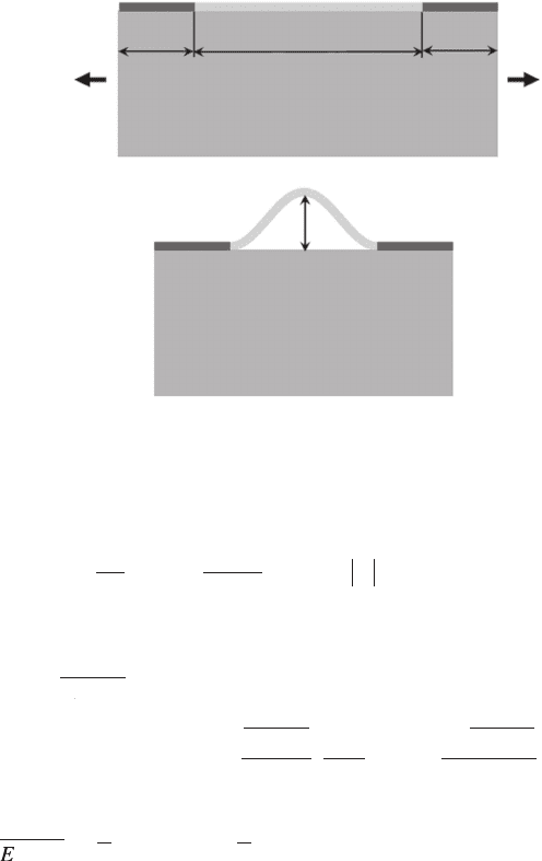
Figure 14.5 shows a schematic diagram of the device islands and interconnect
bridges on a prestrained, thick elastomeric substrate prior to encapsulation.
The device islands (length L
island
) and interconnect bridges (length L
bridge
) are
chemically (well) and loosely (poorly) bonded to the substrate, respectively.
Release of the prestrain e
pre
in the substrate leads to compression, which
buckles the interconnect bridges because they are much narrower and have
much lower bending stiffness than the device islands.
The width of interconnect bridge is much smaller than the width of device
island such that the rotation at the ends of bridges is very small. This is veried
by nite element analysis (Kim et al., 2008c). Therefore, the ‘bridge’-like
interconnect is modeled as a beam with clamped ends since its thickness
is much smaller than any other characteristic length. The beam, however,
undergoes large rotation once the interconnect bridge buckles. The buckling
prole of the interconnect bridge can be expressed as
Si island
Transfer elements to prestrained
elastomeric substrate
Stretchable interconnect
PDMS
Release
L + DL
L + DL
L
L
Stretchable
silicon device
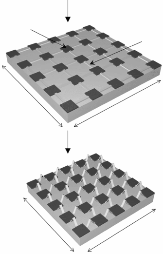
14.4 A schematic illustration of the process for fabricating electronics
with two-dimensional non-coplanar mesh designs on a complaint
substrate. Reprinted with permission from Song et al. (2009b),
Copyright 2009 American Institute of Physics.
ThinFilm-Zexian-14.indd 348 7/1/11 9:45:18 AM
349Controlled buckling of thin fi lms on compliant substrates
© Woodhead Publishing Limited, 2011
w
A
X
L
XL =
2
1 + cos
2
for
0
bridge
p
Ê
Ë
Á
ˆ
¯
˜
£
bbridge
/2
[14.9]
where A
0
is the buckle amplitude to be determined, and X = 0 denotes the
center of the bridge. This gives the bending energy in terms of the bending
stiffness
E
I
EIE
b
r
i
d
g
e
(per unit width) in the interconnect bridge
U
EI
dw
dX
bending
–L /2
L/2
bridge
2
=
2
bridge
bridge
Ú
Ê
2
ËË
Á
ˆ
¯
˜
2
dX
EI
L
A =
4
bridge
bridge
3
0
2
p
[14.10]
For an interconnect bridge with the Young’s modulus E and uniform thickness
h,
E
I
EIE
b
r
i
d
g
e
= Eh
3
/12, where E = E/(1 – n
2
) is the plane-strain modulus, and
n is the Poisson’s ratio.
The membrane energy can be obtained through the membrane strain, which
is related to the out-of-plane displacement w and the axial displacement u by
e
membrane
= du/dX + (dw/dX)
2
/2. The force equilibrium, dN/dX = 0, requires
a constant axial force N in the interconnect bridge, and therefore a constant
membrane strain. Releasing the prestrain e
pre
in the elastomeric substrate leads
to compression in the interconnect bridges. When this compression exceeds
the critical value, the interconnect bridges buckle to form the popup structure
similar to Fig. 14.1(c). The length of elastomeric substrate underneath the
interconnect bridge changes from L
bridge
before the release of prestrain to
L
island
/2 L
island
/2L
bridge
Interconnect Device island
Prestrain
Substrate
Relaxed substrate
Prestrain
A
0
14.5 A schematic diagram of the mechanics model for non-coplanar
mesh structure prior to encapsulation. Reprinted with permission
from Wu et al. (2010), Copyright 2010 Elsevier Ltd.
ThinFilm-Zexian-14.indd 349 7/1/11 9:45:19 AM

350 Thin fi lm growth
© Woodhead Publishing Limited, 2011
L
bridge
/(1 + e
pre
) after the prestrain is completely released. This relates the
axial displacement u to the prestrain e
pre
by
–L
/2
L/
2
br
idge
bridgebr
pr
e
prepr
br
i
bribr
br
idge
bridgebr
br
L/
br
L/
idge
L/
idge
L/
bridgebr
L/
br
L/
idge
L/
br
L/
=
1 +
–
Ú
–L
Ú
–L
du
L
L
e
dge
ddged
br
idge
bridgebr
pr
e
prepr
pr
e
prepr
= –
1 +
L
e
e
[14.11]
It gives the axial displacement u = pA
0
2
/(16L
bridge
)sin(4pX/L
bridge
) – (e
pre
X)/
(1 + e
pre
). The membrane strain can be obtained as
e
p
e
e
memb
ra
ne
2
br
idge
bridgebr
0
2
pr
e
prepr
pr
e
prepr
=
4
–
1 +
L
A
0
A
0
2
L
2
L
[14.12]
The membrane energy in the interconnect bridge is then obtained as
U
Eh
memb
ra
ne
–L
/2
L/
2
br
Eh
br
Eh
idge
bridgebr
memb
r
=
br
idge
bridgebr
br
L/
br
L/
idge
L/
idge
L/
bridgebr
L/
br
L/
idge
L/
br
L/
Ú
–L
Ú
–L
2
e
an
aana
e
br
idge
bridgebr
0
br
idge
bridgebr
pr
=
–
2
4
2
2
32
4
dX
Eh
br
Eh
br
A
0
A
0
L
p
p
e
Ê
Ë
Á
Ê
Á
Ê
Ë
Á
Ë
ˆ
¯
˜
ˆ
˜
ˆ
¯
˜
¯
eee
prepreprepr
pr
e
prepr
1 +
e
È
Î
Í
È
Í
È
Í
Î
Í
Î
Í
Í
Í
˘
˚
˙
˘
˙
˘
˙
˚
˙
˚
˙
˙
˙
2
[14.13]
where
Eh
br
Eh
br
Eh
idge
bridgebr
is the tensile stiffness (per unit width) of interconnect bridges.
For an interconnect bridge with the Young’s modulus E and uniform thickness
h,
Eh
br
Eh
br
Eh
idge
bridgebr
= Eh.
The displacement in Eq. 14.9 induces negligible deformation in the
device islands and elastomeric substrate
(Song et al., 2009b) such that their
strain energy can be neglected. The total energy is the sum of bending and
membrane energy in the thin lm and the minimization of total energy,
d(U
bending
+ U
membrane
)/dA
0
= 0, gives the buckle amplitude,
A
L
0
A
0
A
br
idge
bridgebr
pr
e
prepr
pr
e
prepr
c
=
2
1 +
–
p
e
e
e
[14.14]
where
e
p
c
2
bridge
bridge
bridge
2
=
4 EI
Eh L
is the critical buckling strain of a doubly clamped
beam. When the prestrain is smaller than e
c
/(1 – e
c
), the interconnect bridge
remains at and does not buckle. Once the prestrain exceeds e
c
/(1 – e
c
), the
interconnect bridge buckles. The membrane strain in Eq. 14.13 becomes
e
membrane
= – e
c
, i.e., the membrane strain is a constant – e
c
after buckling.
For an interconnect bridge made of n layers of materials, the
tensile and bending stiffness can be obtained by
Eh Eh
bridge
i=1
n
ii
= S
and
ThinFilm-Zexian-14.indd 350 7/1/11 9:45:20 AM

351Controlled buckling of thin films on compliant substrates
© Woodhead Publishing Limited, 2011
EI Eh bh
h
bridge
i=1
n
ii
j=1
i
j
i
= – – SS
2
Ê
Ë
Á
ˆ
¯
˜
È
Î
ÍÍ
˘
˚
˙
2
=
1
12
i=1
n
i
i
3
S Eh
, respectively. Here E
i
=
E
i
/(1 – n
i
2
) is the plane-strain modulus, h
i
is the thickness of the ith layer
from the top surface and
bEhhhEh
j
i
=
1
2
i=1
n
ii
=1
jibridge
SS–
Ê
Ë
Á
ˆ
¯
˜
is the distance
between the top surface and neutral mechanical plane. The maximum
(compressive) strain in the interconnect bridge is the sum of membrane and
bending strains. The bending strain in the interconnect bridge can be obtained
by ky, where y is the distance from the neutral mechanical plane, and k is
the maximum curvature given by
k
p
e
e
e
= max =
4
+
–
2
bridge
pre
pre
dw
dX
L
2
1
Ê
Ë
Á
ˆ
¯
˜
cc
.
The membrane strain is shown to be a constant e
membrane
= – e
c
, which is
negligible compared to the bending strain.
For the interconnect bridges made of Si (h = 50 nm, L
bridge
= 20 mm) in
experiments, the neutral mechanical plane is b = h/2 = 25 nm from the top
surface. The critical buckling strain is extremely small, e
c
= 0.0021%. The
measured bridge length is 17.5 mm after relaxation, which corresponds to a
prestrain e
pre
= 14.3%. The amplitude predicted by Eq. 14.10 is A
0
= 4.50
mm, which agrees well with the experimentally measured value 4.76 mm.
The maximum strain in the interconnect bridge is 0.56%, which is smaller
than the fracture strain of silicon (~1%), and much smaller than the prestrain.
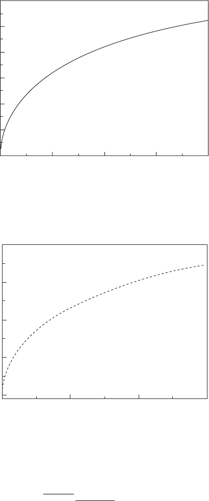
The maximum strain versus the prestrain is shown in Fig. 14.6 and for 1%
interconnect strain, the prestrain can reach 68%.
For the interconnect bridges made of polyimide (h
1
= h
4
= 1.2 mm, E
1
= E
4
= 2.5 GPa, v
1
= v
4
= 0.34), Au (h
2
= 0.15 mm, E
2
= 78 GPa, v
2
= 0.44) and
Sio
2
(h
3
= 0.05 mm, E
3
= 70 GPa, v
3
= 0.17) (Kim et al., 2009), the neutral
mechanical plane is b = 1.30 mm from the top surface. The stretchability of
the system is determined by the maximum strain in the critical layer, which
is made of brittle material. In this case, the critical layer in the interconnect
bridge is Au or Sio
2
. For an interconnect bridge with L
bridge
= 460 mm, the
critical buckling strain is e
c
= 0.0032%. Figure 14.7 shows the maximum
strain
0.0028 /(1 + )
prepre
ee
in Au or Sio
2
versus the prestrain. For a large
prestrain 100%, the maximum strain is small, 0.2%.
The nite element method is used to study the silicon island (L
island
¥
L
island
) on PDMS substrate [(L
island
+ L
bridge
) ¥ (L
island
+ L
bridge
)]. The island
is modeled by shell elements since its thickness is much smaller compared
with other lengths. The substrate is modeled by 3D solid elements. The
island is bonded to the substrate by sharing the same nodes. Periodic
conditions are applied on the lateral surfaces (X–Z and Y–Z planes).
The buckled interconnect bridge gives the axial force
NEh =
bridge c
e
and
ThinFilm-Zexian-14.indd 351 7/1/11 9:45:21 AM
352 Thin film growth
© Woodhead Publishing Limited, 2011
bending moment
MEI
A
L
=
2
()
bridge
2
bridge
p
0
2
, which are applied over the width
w
bridge
on each edge of the island. Since the axial force N scales with the
critical buckling strain e
c
, the strain due to the axial force N is negligible
Maximum strain (%)
1.2
1.0
0.8
0.6
0.4
0.2
0.0
0 20 40 60 80
Prestrain (%)
14.6 The maximum strain in the interconnect bridge versus the
prestrain. The material properties and geometry of interconnect
bridges are given in Section 14.3.1. Reprinted with permission from
Song et al. (2009b), Copyright 2009 American Institute of Physics.
Maximum strain (%)
0.20
0.15
0.10
0.05
0.00
0 20 40 60
Prestrain (%)
14.7 The maximum strain in the interconnect bridge versus the
prestrain. The material properties and geometry of interconnect
bridges are given in Section 14.3.1. Reprinted with permission from
Wu et al. (2010), Copyright 2010 Elsevier Ltd.
ThinFilm-Zexian-14.indd 352 7/1/11 9:45:22 AM
353Controlled buckling of thin films on compliant substrates
© Woodhead Publishing Limited, 2011
compared to the strain due to the bending moment M, i.e., bending
dominates.
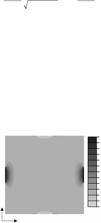
Figure 14.8 shows the strain distribution e
xx
in a Si island (E
island
= 130
GPa, n
island
= 0.27, length L
island
= 20 mm, and thickness h
island
= 50 mm) on
a PDMS substrate (E
substrate
= 2 MPa, n
substrate
= 0.48). The axial force and
bending moment result from the buckled interconnect bridge(E
bridge
= 130
GPa, L
bridge
= 20 mm, h
bridge
= 50 nm, w
bridge
= 4 mm, and e
pre
= 14.3%). The
maximum strain occurs at the interconnect/island boundary.
The maximum strain in the device island is shown (Song et al., 2009b)
to
be
41
pee
yEILEI
bridge prepre bridge island
/()/( )+
where y is the distance from
the neutral plane. In practice, the bending stiffness of the device island is
much larger than that of the interconnect bridge. Therefore, the strain in
the device island is negligible and we only need to focus on the strain in
interconnect bridges. Considering the multi-layer non-coplanar mesh design
used in the electronic eye camera (Ko et al., 2008), the interconnect bridges
consist of a thin layer of patterned metal (360 mm long, 50 mm wide, 150
nm thick gold) on a polyimide (PI) layer and the islands consists of (500 ¥
500 mm
2
in area, 1.2 mm thick) silicon layer with a capping 1.5 mm thick
polyimide. The elastic moduli and Poisson’s ratios of metal and PI are E
metal
= 78 GPa, n
metal
= 0.44, E
PI
= 2.5 GPa and n
PI
= 0.34. Figure 14.9 shows
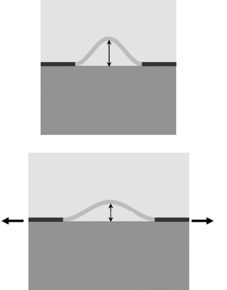
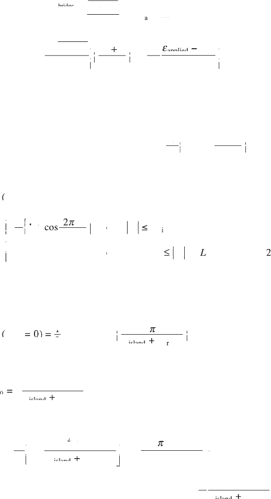
the maximum metal strain in interconnects and Si strain in device islands
versus the prestrain. The metal strain is much larger than the Si strain and
both strains are much smaller than the fracture strain 1% even under 100%
prestrain.
y
x
e
xx
(%)
0.45
0.35
0.25
0.15
0.05
–0.05
14.8 Distribution of the strain e
xx
in islands (20 ¥ 20 mm) when the
interconnect bridge relaxes from 20 mm to 17.5 mm. Reprinted with
permission from Song et al. (2009b), Copyright 2009 American
Institute of Physics.
ThinFilm-Zexian-14.indd 353 7/1/11 9:45:22 AM
354 Thin film growth
© Woodhead Publishing Limited, 2011
14.3.2 Analysis for post-encapsulation
In practice, the non-coplanar mesh designs require top surface encapsulation
layers to provide mechanical and environmental protection. In order to
provide minimal restriction of the free deformation of the non-coplanar
bridges, the encapsulation layer should be an elastomer, with properties not
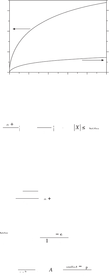
too dissimilar from the substrate. Figure 14.10 shows a schematic diagram
of the encapsulated system subject to the applied strain e
applied
. A compliant
elastomeric material (e.g., PDMS) is cast and cured on top of the buckled
interconnect bridges and device islands. The analysis below focuses on the
stretchability, i.e., the maximum applied strain that leads to the failure of
the system.
once e
applied
is applied, the amplitude of the interconnect bridge changes
from A
0
to A
0
+ A, where A is the increase of the buckle amplitude due to
the applied strain. The buckling prole of the encapsulated interconnect
bridges becomes
Encapsulation
Substrate
Stretched encapsulation
Stretched substrate
A
0
A
0
+ A
e
applied
e
applied
14.9 The maximum metal strain interconnect bridge (metal/PI) and Si
strain in islands (PI/Si) versus the prestrain.
ThinFilm-Zexian-14.indd 354 7/1/11 9:45:22 AM
355Controlled buckling of thin fi lms on compliant substrates
© Woodhead Publishing Limited, 2011
w
AA
X
L
=
AA +AA
2
1 + cos
2
f
or
for f
or or
0
AA
0
AA
br
idge
bridgebr
p
Ê
Ë
Á
Ê
Á
Ê
Ë
Á
Ë
ˆ
¯
˜
ˆ
˜
ˆ
¯
˜
¯
XL
XL
XXLX
XL ≤XL
/
XL /XL
2
br
/
br
/
idge
/
idge
/
bridgebr
/
br
/
idge
/
br
/
,
[14.15]
where the increase of the amplitude A is to be determined by energy
minimization. The total energy of the system consists of the bending energy
U
bending
and membrane energy U
membrane
in the thin lm as well as the substrate
energy U
substrate
and the energy in the encapsulation layer U
encapsulation
. The
bending and membrane energy can be obtained following the same procedure
used in Section 14.3.1. The bending energy in the interconnect bridge is
given from Eq. 14.9 by replacing A
0
with A
0
+ A,
U
EI
L
AA
bending
br
idge
bridgebr
br
idge
bridgebr
3
L
3
L
0
AA
0
AA
=
(
(
L
(
L
AA (AA
br
(
br
idge
(
idge
bridgebr
(
bridgebr
3
(
3
L
3
L
(
L
3
L
AA +AA
)
AA )AA
p
4
2
[14.16]
The axial displacement u is related to the prestrain e
pre
and applied strain
e
applied
by
–L
/2
L/
2
br
idge
bridgebr
applie
dp
re
br
idge
bridgebr
br
L/
br
L/
idge
L/
idge
L/
bridgebr
L/
br
L/
idge
L/
br
L/
=
Ú
–L
Ú
–L
du
L
ee
applie
ee
applie
dp
ee
dp
dp
–
dp
ee
dp
–
dp
1 +
11 +1
pr
e
prepr
e
[14.17]
It gives the membrane strain in the interconect bridge
e
p
ee
memb
ra
ne
br
idge
bridgebr
applie
ee
applie
ee
d
ee
d
ee
=
(
(
p
(
p
)
+
ee
–
ee
2
2
(
2
(
0
2
4
(
4
(
L
(
L
(
2
L
2
(
2
(
L
(
2
(
AA
(AA (
+AA +
)AA )
0
AA
0
pr
pprp
e
prepr
pr
e
prepr
1 +
e
[14.18]
Maximum metal strain in
interconnects (%)
Maximum Si strain in islands (%)
0.6
0.4
0.2
0.0
0.6
0.4
0.2
0.0
0 20 40 60 80 100
Prestrain (%)
14.10 A schematic diagram of the encapsulated system subject
to stretching. Reprinted with permission from Wu et al. (2010),
Copyright 2010 Elsevier Ltd.
ThinFilm-Zexian-14.indd 355 7/1/11 9:45:23 AM
356 Thin fi lm growth
© Woodhead Publishing Limited, 2011
and membrane energy in the interconnect bridge
U
Eh
memb
ra
ne
–L
/2
L/
2
br
Eh
br
Eh
idge
bridgebr
memb
r
=
br
idge
bridgebr
br
L/
br
L/
idge
L/
idge
L/
bridgebr
L/
br
L/
idge
L/
br
L/
Ú
–L
Ú
–L
2
e
an
aana
e
br
idge
bridgebr
br
idge
bridgebr
2
=
32
+
2
4
0
2
4
dX
dX
Eh
br
Eh
br
AA
0
AA
0
L
p
p
AA+AA
Ê
Ë
Á
Ê
Á
Ê
Ë
Á
Ë
ˆ
¯
˜
ˆ
˜
ˆ
¯
˜
¯
ee
eeee
e
applie
ee
applie
ee
dp
ee
dp
ee
re
pr
e
prepr
ee
dp
ee
–
ee
dp
ee
1 +
È
Î
Í
È
Í
È
Í
Î
Í
Î
Í
Í
Í
˘
˚
˙
˘
˙
˘
˙
˚
˙
˚
˙
˙
˙
2
[14.19]
The substrate and encapsulation layer are modeled as semi-in nite solids
because they are much thicker than the interconnect bridges and device
islands. In order to obtain the energy in the substrate and encapsulation
layer, we only need to consider the deformation resulting from the increase
of the amplitude because the deformation due to
A
X
L
0
A
0
A
2
2
1 + cos
br
idge
bridgebr
p
Ê
Ë
Á
Ê
Á
Ê
Ë
Á
Ë
ˆ
¯
˜
ˆ
˜
ˆ
¯
˜
¯
in Eq.
14.16 is negligible (Song et al., 2009a). The normal displacement on the
surface Y = 0 is
wX
Y
AX
L
XL
XL
(,
wX(,wX
= 0)
=
1 +
AX
1 +
AX
f
f
AX
f
AX
L
f
L
or
for f
XL ≤XL
br
idge
bridgebr
br
2
2
AX2AX
AX
f
AX2AX
f
AX
co
fco f
s
fs f
AX
p
AX
f
p
f
AX
f
AX
p
AX
f
AX
Ê
AX
Ê
AX
Ë
Á
Ê
Á
Ê
AX
Ê
AX
Á
AX
Ê
AX
Ë
Á
Ë
ˆ
f
ˆ
f
¯
f
¯
f
f
˜
f
f
ˆ
f
˜
f
ˆ
f
¯
˜
¯
f
¯
f
˜
f
¯
f
idge
bridgebr
iidgei
bribridgebribr
br
idge
bridgebr
island
br
idge
bridgebr
/2
0f
or
0for0f
/2
(
island
(
island
)/
LX
LX
LX
br
LX
br
idge
LX
idge
bridgebr
LX
bridgebr
/2LX/2
LL
( LL(
island
(
island
LL
island
(
island
+ LL+
££
££
LX££LX
LX££LX
222
Ï
Ì
Ô
Ï
Ô
Ï
Ô
Ì
Ô
Ì
Ô
Ô
Ô
Ó
Ô
Ì
Ô
Ì
Ô
Ó
Ô
Ó
Ô
Ô
Ô
[14.20]
It should be noted that this displacement is periodic over [–(L
isaland
+ L
bridge
)/2,
(L
isaland
+ L
bridge
)/2], and can be expressed in the Fourier series as
wX
Ya
Ya
a
lX
LL
l
(,
wX(,wX
Ya =Ya
)
Ya )Ya
Ya =Ya
1
Ya
1
Ya
2
Ya
2
Ya
+
co
s
2
LL +LL
0
l=
1
island
LL
island
LL
b
)0 )
Ya )Ya0Ya )Ya
S
•
p
lX
p
lX
ri
rrir
dge
Ê
Ë
Á
Ê
Á
Ê
Ë
Á
Ë
ˆ
¯
˜
ˆ
˜
ˆ
¯
˜
¯
[14.21]
where a
l
is obtained by
aA
L
LL
0
aA
0
aA
br
idge
bridgebr
island
LL
island
LL
br
idge
bridgebr
aA =aA
LL +LL
for l = 0, [14.22]
and
a
A
l
lL
LL
l
2
lL
2
lL
br
idge
bridgebr
2
lL
2
lL
island
br
idge
bridgebr
=
1 –
(
LL( LL
island
(
island
LL
island
LL( LL
island
LL
LL+ LL
)
p
l
p
l
2
È
Î
Í
È
Í
È
Í
Î
Í
Î
Í
Í
Í
˘
˚˚˚
˙
˘
˙
˘
˙
˚˚˚
˙
˚˚˚
˙
˙
˙
>
–1
br
idge
bridgebr
island
br
idge
bridgebr
si
n
f
or
for f
or or
lL
LL
island
LL
island
+LL +
l
l
p
lL
p
lL
0
[14.23]
For the special case of l = (L
isaland
+ L
bridge
)/L
bridge
,
a
A
L
LL
l
=
LL +LL
br
idge
bridgebr
island
LL
island
LL
br
idge
bridgebr
2
.
ThinFilm-Zexian-14.indd 356 7/1/11 9:45:25 AM
357Controlled buckling of thin fi lms on compliant substrates
© Woodhead Publishing Limited, 2011
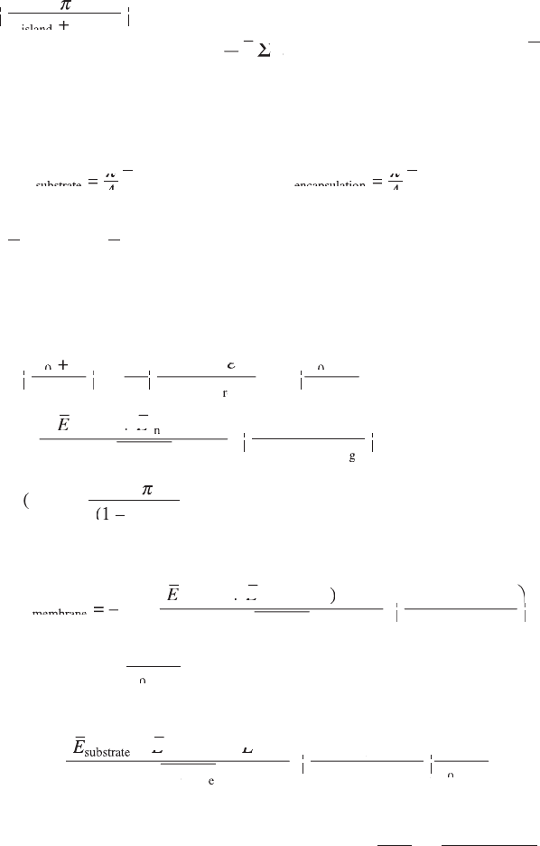
For a semi-in nite solid subject to normal displacement w(X,Y = 0) =
a
lX
LL
l
co
s
2
p
lX
p
lX
island
LL
island
LL
br
idge
bridgebr
LL +LL
Ê
Ë
Á
Ê
Á
Ê
Ë
Á
Ë
ˆ
¯
˜
ˆ
˜
ˆ
¯
˜
¯
on its surface, the strain energy stored over the period
L
isaland
+ L
bridge
(per unit width) is
p
4
El
a
ElaEl
S
ElSEl
l=
1
l
2
•
(Huang et al., 2005), where E
is the plane-strain modulus of the semi-in nite solid. Therefore, the strain
energies in the substrate and encapsulation layer (over the period L
isaland
+
L
bridge
, per unit width) are
UE
UE
la
s
UE
s
UE
ubs
UE
ubs
UE
tr
UE
tr
UE
at
UE
at
UE
es
UE
es
UE
ubs
tr
at
e
l=
1
l
2
UE =UE
UE
es
UE =UE
es
UE
es
es
UE
es
UE UE
es
UE
ubs
ubs
tr
tr
at
at
e
e
UE
es
UE UE
es
UE
p
UE
p
UE
UE
es
UE
4
UE
es
UE
4
es
4
es
UE
es
UE
4
UE
es
UE
UE
es
UE UE
es
UE
4
UE
es
UE UE
es
UE
S
•
and
UE
UE
la
encapsulatio
UE
encapsulatio
UE
ne
UE
ne
UE
ncap
su
latio
n
l=
1
l
2
UE =UE
UE
ne
UE =UE
ne
UE
4
ne
4
ne
UE
ne
UE
4
UE
ne
UE
p
UE
p
UE
S
•
[14.24]
where E
substrate
and E
encapsulation
are the plane-strain moduli of the substrate
and encapsulation layer.
The minimization of total energy, d(U
bending
+ U
membrane
+ U
substrate
+
U
encapsulation
)/dA = 0, gives a cubic equation for the amplitude A,
AA
L
0
AA
0
AA
3
2
4
AA +AA
+
1 +
br
idge
bridgebr
applie
dp
re
p
Ê
Ë
Á
Ê
Á
Ê
Ë
Á
Ë
ˆ
¯
˜
ˆ
˜
ˆ
¯
˜
¯
p
ee
applie
ee
applie
dp
ee
dp
–
dp
–
ee
–
dp
–
e
re
rrer
c
br
idge
bridgebr
s
ubs
tr
at
ee
+
+
(
s
(
s
ubs
(
ubs
tr
(
tr
at
(
at
ee
(
ee
e
Ê
Ë
Á
Ê
Á
Ê
Ë
Á
Ë
ˆ
¯
˜
ˆ
˜
ˆ
¯
˜
¯
AA
+AA +
L
EE
ee
EE
ee
( EE(
s
(
s
EE
s
(
s
ubs
(
ubs
EE
ubs
(
ubs
tr
(
tr
EE
tr
(
tr
at
(
at
EE
at
(
at
ee
(
ee
EE
ee
(
ee
+ EE+
ee
+
ee
EE
ee
+
ee
0
AA
0
AA
4
ncap
nncapn
su
latio
n
br
idge
bridgebr
br
idge
bridgebr
island
br
id
bridbr
)
p
5
Eh
br
Eh
br
f
L
LL
island
LL
island
+LL +
ge
ggeg
= 0
Ê
Ë
Á
Ê
Á
Ê
Ë
Á
Ë
ˆ
¯
˜
ˆ
˜
ˆ
¯
˜
¯
A
[14.25]
where
fx
lx
ll
x
()
fx()fx
=
()
lx()lx
(
ll(ll
ll1 – ll
)
l=
1
S
•
si
n
2
22
x
22
x
2
()
p
()
lx()lx
p
lx()lx
. The numerical method is then used to solve
this cubic equation.
The membrane strain in Eq. 14.18 can be rewritten using Eq. 14.25 as
ee
memb
ee
memb
ee
ra
ee
ra
ee
ne
ee
ne
ee
c
s
ubs
tr
at
ee
ncap
su
latio
n
ee
= –
ee
–
(
s
(
s
ubs
(
ubs
tr
(
tr
at
(
at
ee
(
ee
EE
ee
EE
ee
( EE(
s
(
s
EE
s
(
s
ubs
(
ubs
EE
ubs
(
ubs
tr
(
tr
EE
tr
(
tr
at
(
at
EE
at
(
at
ee
(
ee
EE
ee
(
ee
+ EE+
ee
+
ee
EE
ee
+
ee
)))
br
idge
bridgebr
br
idge
bridgebr
br
idge
bridgebr
island
br
idge
bridgebr
L
Eh
br
Eh
br
f
L
LL
+LL +
island
LL
island
p
3
Ê
Ë
Á
Ê
Á
Ê
Ë
Á
Ë
ˆˆˆ
¯
˜
ˆˆˆ
˜
ˆˆˆ
¯
˜
¯
¥
A
AA
+AA +
0
AA
0
AA
[14.26]
where – e
c
is the membrane strain from the release of prestrain in Section
14.3.1, and
–
(
)
s
(
s
(
ubs
(
ubs
(
tr
(
tr
(
at
(
at
(
ee
(
ee
(
ncap
su
latio
nb
)
nb
)
ri
dge
br
id
bridbr
g
EE
( EE(
+ EE+
(
s
( EE(
s
(
(
ubs
( EE(
ubs
(
(
tr
( EE(
tr
(
(
at
( EE(
at
(
ee
EE
ee
(
ee
( EE(
ee
(
+
ee
+ EE+
ee
+
L
nb
L
nb
Eh
br
Eh
br
p
3
eee
br
idge
bridgebr
island
br
idge
bridgebr
br
br
idge
idge
bridgebr
bridgebr
f
L
LL
island
LL
island
+LL +
A
AA
+ AA+
Ê
Ë
Á
Ê
Á
Ê
Ë
Á
Ë
ˆ
¯
¯
˜
ˆ
˜
ˆ
¯
˜
¯
0
0
AA
0
AA
is the
additional membrane strain due to the applied strain. The bending strain is
obtained by ky, where the maximum curvature is
k
p
= max =
+
bridge
dw
dX
AA
L
2
2
2
0
2
2
Ê
Ë
Á
ˆ
¯
˜
()
and y is the distance from the neutral mechanical plane. Figure 14.11 shows
the (absolute value of) membrane strain and maximum bending strain
ThinFilm-Zexian-14.indd 357 7/1/11 9:45:27 AM
