Buschow K.H.J. (Ed.) Concise Encyclopedia of Magnetic and Superconducting Materials
Подождите немного. Документ загружается.


Engdahl G (ed.) 1999 Handbook of Giant Magnetostrictive Ma-
terials: Physics and Device Applications. Academic Press,
London
Fujita A, Fukamichi K 1999 Giant volume magnetostriction
due to the itinerant electron metamagnetic transition in
La(Fe–Si)
13
compounds. IEEE Trans Magn MAG-35,
3796–801
Hubert A, Scha
¨
fer R 1998 Magnetic Domains. Springer, Berlin
James R D, Kinderlehrer D 1994 Theory of magnetostriction
with application to Terfenol-D. J. Appl. Phys. 76, 7012–4
Ne
´
el L 1937 E
´
tudes sur le moment et le champ mole
´
culaire des
ferromagne
´
tiques. Ann. Phys. 8, 237–308
Quandt E, Ludwig A 1999 Giant magnetostrictive multilayers.
J. Appl. Phys. 85, 6232–7
Sablik M, Jiles D C 1993 Coupled magnetoelastic theory of
magnetic and magnetostrictive hysteresis. IEEE Trans. Magn
MAG-29, 2113–23
Sander D, Enders A, Kirschner J 1999 Stress and magnetic
properties of surfaces and ultrathin films. J. Magn. Magn.
Mater. 200, 439–55
Tremolet de Lacheisserie E du, 1993 Theory and Applications of
Magnetoelasticity. CRC Press, Boca Raton, FL
Wassermann E F 1990 Invar: moment-volume instabilities in
transition metals and alloys. In: Buschow K H J, Wohlfarth
E P (eds.) Ferromagnetic Materials. North-Holland, Amster-
dam, Vol. 5, Chap. 3, pp. 237–322
Wu R Q, Chen L J, Shick A, Freeman A J 1998 First principles
determination of magnetocrystalline anisotropy and magne-
tostriction in bulk and thin film transition metals. J. Magn.
Magn. Mater 177–81, 1216–9
W. Andrae and R. Mattheis
IPHT Jena, Germany
D. Berkov
Innovent, Jena, Germany
Superconducting Machines: Energy
Distribution Components
Most of the potential applications of superconduc-
tivity in power systems benefit from zero resistance
and high critical current densities in the supercon-
ducting state thus reducing losses and size of com-
ponents, for example the generator, transformer,
cable (see Superconducting Wires and Cables: Low-
field Applications), SMES (superconducting magnetic
energy storage) and motor. But, there is also a po-
tential application which utilizes the transition from
the superconducting to the normal-conducting state
in order to limit fault currents. The device is usually
referred to as a superconducting fault current limiter
(SCFCL).
1. Superconducting Transformer
Transformers are major components of power
systems. They allow generation, transmission, and
distribution of electrical energy at different voltage
levels, leading to economical benefits.
Replacing the copper windings in transformers by
a superconductor (SC) offers several opportunities.
First it offers reduction in losses, owing to the zero
resistance of the conductor. Second it offers reduc-
tion of size and weight. Because of higher current
densities, the mass of conductor needed can be very
small. By applying more winding turns/length in the
coils, the amount of iron can be reduced as well. Even
iron-free transformers might become feasible. Third,
large conventional power transformers are oil-cooled.
A superconducting transformer would be more envi-
ronmentally benign.
In a conventional transformer design the SC will be
exposed to alternating magnetic fields up to about
0.3 T. In designs with increased winding turns/length
(to reduce iron volume) an even higher magnetic field
(B) would be reached. The main challenges for the SC
material are high j
c
losses, low ac losses at high B, and
low cost. Since transformers generate losses not only
in the conductor but also in the iron core, it is ad-
visable to leave the core of an SC transformer at
room temperature, where cooling is cheaper. Such a
design however, poses serious requirements on the
cryostat, which would need a warm bore and should
ideally be made of nonmagnetic and electrically in-
sulating material in order to avoid additional losses.
1.1 Status of Research
Several SC transformers based on LTS have been
built in the past, having a rated power of a few
100 kV A. Commercially available LTS (low temper-
ature superconductor) wires meet technical and eco-
nomical needs (j
c
about 50 kA cm
2
, a.c. losses
o10
5
WA
1
m
1
at 0.1 T. However, commerciali-
zation of LTS transformers has so far been prohib-
ited by the rather high cooling costs, mainly caused
by thermal losses through cryostat and current leads.
HTS offers the opportunity to operate SC trans-
formers at 77 K, which could reduce cooling costs to
an acceptable level. But, HTS (high temperature su-
perconductor) wires are not nearly as mature as the
LTS wires. At present Bi2223 wire is the only HTS
available of sufficient length, which could be operated
at 77 K. First prototypes based on these materials
have been built. A 630 kV A prototype has already
been operated for one year under realistic conditions.
Even though the technical feasibility has been proven,
the present Bi2223 wire will hardly allow a commer-
cial SC transformer to be built.
At present the 77 K field dependence of j
c
(j
c
(B)), of
the wire is too strong and the a.c. losses and wire
costs are too high. J
c
(B) can be improved by oper-
ating the transformer at a lower temperature, which
of course increases cooling costs. Bi2223 conductors
with reduced a.c. losses are under development. The
1130
Superconducting Machines: Energy Distribution Component s

maximum acceptable losses are in the order of
10
4
WA
1
m
1
at 0.1 T; present values are about
10 times higher.
YBCO (YBa
2
Cu
3
O
7–x
) tapes, even though only
available at length of few meters, offer better j
c
(B)
and potentially lower cost. The a.c. losses in mag-
netic fields parallel to the YBCO tape will be negli-
gible. However, it will be a great challenge to reduce
the losses due to perpendicular field components
(occurring mainly at the end of the coils) to an ac-
ceptable value. Nevertheless, considering the status of
early twenty-first century technology, the material
seems to have the highest potential for transformer
applications.
2. Superconducting Fault Current Limiter
In electric power systems short circuits might be
caused by aged or accidentally damaged insulation
or by lightning striking an overhead line. The sub-
sequent fault current is only limited by the impedance
of the system between location of fault and power
sources. All components of the power system have to
be designed to withstand the stresses caused by a
short circuit. The higher the fault current anticipated,
the higher the costs for the equipment.
Many approaches for realising fault current limit-
ers (FCL) have been based on components with
strongly nonlinear current–voltage characteristics
(e.g., semiconductors, iron-core reactors, and super-
conductors). Among the nonlinear materials, super-
conductors stand out because of their unique
transition from zero to finite resistance. FCLs which
utilize this transition will be referred to as supercon-
ducting fault current limiters (SCFCLs). FCLs which
are based on other concepts but might still use SC,
e.g., in order to realize low-loss coils, will not be dis-
cussed here. There are essentially two concepts in
SCFCLs, i.e., the ‘‘resistive’’ and the ‘‘shielded core’’
concepts.
2.1 Resistive SCFCL
The most straightforward concept in an SCFCL is
the so called ‘‘resistive SCFCL’’ in which the SC is
directly connected in series to the line to be protected.
For cooling, the SC might be immersed in a coolant
(e.g., liquid helium for LTS or liquid nitrogen for
HTS), which is chilled by using a refrigerator.
The cross-section of the SC is determined such
that, at nominal current, the SC is operated inside the
superconducting state, i.e., at zero resistance, so that
its interference with the network is negligible. How-
ever, the SC only has true zero impedance for direct
current (d.c.)-currents. For the more common a.c.
applications the finite length of the SC leads to a
finite reactance and the alternating magnetic field
generated by the current produces a.c. losses. They
both depend very strongly on the geometry of the SC,
and can be reduced by optimized conductor archi-
tecture, e.g., in the coils with windings in opposite
directions or meander structures.
In case of a fault, the increase in j will drive the SC
out of the superconducting region into a flux–flow
regime. The rapidly increasing resistance limits the
current to a value below the unlimited prospective
fault current. The actual limitation behavior depends
very much on the length of the SC and also on the
type of SC material. The three main different limi-
tation behaviors can be realized by just varying the
length of the same SC material.
First, by using a very long conductor, the electric
field E ¼(line voltage)/(conductor length), to which
the SC is exposed during the fault will be very small.
Thus, the corresponding current density will exceed
the nominal value only by a little. The power density
E.
j
dissipated in the SC will be negligible so that the
SC will essentially not warm up (curve 1 in Fig. 1).
This ‘‘constant temperature’’ design gives a very good
limitation. However, the long length of the conductor
will be prohibitively expensive and cause rather high
a.c. losses.
The other extreme design would be using a rather
short conductor, leading to a relatively large E during
the fault. As the fault occurs, the current will increase
essentially unlimited by the small resistivity of the
flux–flow regime and only limited by the impedance
of the power system. However, because of the very
high E.
j
dissipated in the SC, the material will heat up
rapidly and, after a few 100 ms, will become normal
conducting and limit the fault current close to or even
below the nominal value (curve 3 of Fig. 1). This
‘‘fast heating’’ design needs a rather small amount of
SC material. However, the height of the first peak still
depends on the unlimited prospective fault current,
and instantaneous recovery to normal operation is
not possible, since the SC first has to cool down.
Furthermore, severe over voltages may arise from the
abrupt current reduction, caused by the rapid tran-
sition into the normal-conducting state. Last, but not
least, the high E.
j
value during the fault might lead to
the SC being damaged.
Using a conductor of intermediate length will lead
to an intermediate poor density dissipation in the SC.
For the first 10 ms the maximum of the fault current
will be limited to several times (e.g., 5–10) that of the
nominal current. The SC will keep warming up and
after a few tens of milliseconds will enter the normal
conducting region (‘‘slow heating’’ design, curve 2 in
Fig. 1).
2.2 Hot Spots
In the above discussion it is assumed that during
the limitation process the voltage drop is uniform
over the whole length of the conductor. In reality,
1131
Superconducting Machines: Energy Distribution Components
however, SC tends to develop thermal instabilities
called ‘‘hot spots,’’ which are due to the strong cur-
rent and temperature dependence of their resistance.
The common measure for reducing the problem is to
attach a normal conducting ‘‘bypass’’ or ‘‘shunt’’ in
close electrical contact to the SC, which allows the
current to bypass the hot spot. Of course, the bypass
reduces the total normal resistance of the conductor,
which might have to be compensated by increased
length. It should be noted that the problem of exces-
sive heating will also limit the maximum possible
electric field to which the conductor can be exposed
during the fault, i.e., it will also set a lower limit for
the length of the SC.
2.3 Shielded Core SCFCL
The second concept in a SCFCL is often referred to
as the ‘‘shielded core.’’ In this concept the SC is not
connected galvanically in the line, but magnetically.
The device is essentially a transformer, with its pri-
mary normal conducting coil connected in series to
the line to be protected, while the secondary side is a
superconducting tube (i.e., a one turn coil). In normal
operation the iron core sees no magnetic field because
it is completely shielded by the SC, thus the name
‘‘shielded core.’’ Because of the inductive coupling
between the line and the SC, the device is sometimes
also referred to as an ‘‘inductive SCFCL.’’ The volt-
age on the secondary is reduced by the number of the
turns of the primary coil, while the current is in-
creased by the same factor. The SC on the secondary
has to be designed for these values. Assuming an
ideal transformer, the SCFCL will behave exactly like
a resistive SCFCL.
In order to achieve a certain limitation behavior,
both types of SCFCL need the same amount of a
certain SC material. Compared to the resistive
SCFCL, the shielded core SCFCL shows the disad-
vantage of being only applicable for a.c. currents and
having a much larger size and weight. On the other
hand it needs no current leads, which is especially
attractive for high current applications, since the
losses of the leads are proportional to their current-
carrying capability.
2.4 Status of Research
Several SCFCL prototypes with a rated power of
several MVA have been realized based on LTS fol-
lowing the resistive concept. Because of the high j
c
and low heat capacity of LTS the ‘‘fast heating’’ de-
sign was the ‘‘natural’’ choice. However, like in the
Figure 1
Different designs offer different current limitation behaviors. 1, Constant temperature; 2, slow heating; 3, fast heating.
1132
Superconducting Machines: Energy Distribution Component s

case of the transformer, commercialization has so far
been prohibited by the rather high cooling costs.
To date, the largest HTS SCFCL prototype that
has been built utilizes Bi-2212 bulk material. ABB
has realized a three-phase 1.2 MV A prototype based
on tubes of this material. For ceramic HTS, this ge-
ometry is usually more easily realized than long
length conductors. The device is of the ‘‘shielded
core’’ and ‘‘slow heating’’ type, it was successfully
operated for one year under realistic conditions in a
Swiss hydropower plant.
Because of their high critical current density
(1 MA cm
2
) YBCO films are especially suitable for
the ‘‘fast heating design.’’ Siemens has demonstrated
a resistive 300 kV A model based on this material.
The films were deposited on planar ceramic subst-
rates, covered with a gold bypass, and patterned into
meander.
Bi2223 wires are at present not particularly suitable
for SCFCL, because of the low normal resistivity of
the Ag-matrix. However, if this resistivity could be
increased, the wire would be quite suitable for resis-
tive SCFCL and could even allow for the incorpo-
ration of ‘‘current limitation’’ functionality in other
devices. Following this approach, a project led by
ABB in partnership with American Superconduc-
tor and Electricite
´
de France has been launched to
develop a current limiting transformer.
See also: Superconducting Machines: Energy Storage
Bibliography
Fevrier A, Tavergnier J P, Laumond Y, Bekhaled M 1988 Pre-
liminary test on a superconducting power transformer. IEEE
Trans. Magn. 24, 1477–80
Gromoll B, Ries G, Schmidt W, Kraemer H P, Seebacher B,
Utz B, Nies R, Neumueller H W, Balzer E, Fissher S, Heis-
mann B 1999 Resistive fault current limiters with YBCO
films–100 kV A functional model. IEEE Trans. Appl. Super-
cond. 9, 656–9
Hoernfeldt S, Albertsson O, Bonmann D, Koenig F 1993 Power
transformer with superconducting windings. IEEE Trans.
Magn. 29, 3556–8
Paul W, Chen M 1998 Superconducting control for surge cur-
rents. IEEE Spectrum May, 49–54
Paul W, Lakner M, Rhyner J, Unterna
¨
hrer P, Baumann Th,
Chen M, Widenhorn L, Gue
´
rig A 1997 Test of 1.2 MV A
high-T
c
superconducting fault current limiter. Supercond. Sci.
Technol. 10, 914–8
Schwenterly S W, McConnel B W, Demko J A, Fadnek A, Hsu
J, List F A, Walker M S, Hazelton D W, Murray F S, et al.
1999 IEEE Trans. Appl. Supercond. 9, 680–4
Seeber B (ed.) 1998 Handbook of Applied Superconductivity IOP
Publishing, Vol. 2, pp. 1613–26 and 1691–1702
Verhaege T, Cottevieille C, Estop P, Quemener M, Tavergnier J
P, Bekhaled M, Bencharab C, Bonnet P, Laumond Y, Pham
V D, Poumarede C, Therond P G 1996 Experiments with a
high voltage (40 kV) superconducting fault current limiter.
Cryogenics 36, 521–6
Yazawa T, Yoneda E, Nomura S, Tsurunaga K, Urata M,
Ohkuma T, Honjo S, Iwata Y, Hara T 1997 Experiments
with a 6.6 kV A/1 kA single-phase superconducting fault cur-
rent limiter. In: Rogalla H, Blank D H A (eds.) Proceedings
of EUCAS 1997, Third European Conference on Applied
Superconductivity. Institute of Physics Conference Series
Number 158. Institute of Physics, Bristol, Vol. 2, pp. 1183–6
Zueger H 1998 630 KVA high temperature superconducting
transformer. Cryogenics 38, 1169–72
W. Paul
ABB Corporate Research Ltd, Baden-Daettwil
Switzerland
Superconducting Machines: Energy
Storage
Superconducting magnetic energy storage (SMES) is
an emerging technology offering tremendous benefits
to the electric power industry. Many years after its
conception (Ferrier 1970), SMES is still not widely
implemented and its commercial viability is only
slowly being established.
1. Principles of Operation
Electric power has always been available on instant
demand with a high degree of reliability, flexibility,
and control; however, it has never been easy to store
in large quantities on a cost-effective and environ-
mentally sound basis.
In SMES, electric energy is stored by circulating a
current in a superconducting coil, or inductor. Be-
cause no conversion of energy to other forms is in-
volved (e.g., mechanical or chemical), round-trip
efficiency can be very high. The energy stored in a d.c.
inductor is given by
E ¼
1
2
LI
2
ð1Þ
where E is the stored energy, L is the inductance of
the coil (which depends on coil geometry), and I is the
circulated current.
As an energy storage device, SMES is a relatively
simple concept. It stores electric energy in the mag-
netic field generated by d.c. current flowing through a
coiled wire. If the coils were wound using a conven-
tional wire such as copper, the magnetic energy
would be dissipated as heat owing to the resistance of
the wire. However, if the wire is superconducting (no
resistance), then energy can be stored in a persistent
mode, virtually indefinitely, until required.
The SMES coil, a d.c. device, is usually connected
to its load (typically an a.c. device) via an a.c./d.c.
converter, or ‘‘power conditioning system’’ (PCS).
1133
Superconducting Machines: Energy Storage

The architecture of the PCS varies depending on the
application, but in general is based on standard semi-
conductor power switches in arrangements to max-
imize reliability, efficiency, and controllability.
The only loss associated with magnetic storage is
the power needed to keep the coil cryogenically
cooled as required by the superconductor. Addition-
ally, there are minor losses associated with power
transfers through the a.c./d.c. converter. Overall ef-
ficiency of a SMES system is heavily dependent on
size (stored energy) and power rating, as well as on
duty cycle, but in general SMES units can be much
more efficient than many other systems for energy
storage.
2. Applications
In terms of energy storage, SMES competes with
other technologies such as batteries, flywheels, and
capacitors. The choice of technology is determined by
economics (cost) when considering all angles: system
performance, capital and operating costs of the unit,
reliability and maintainability, environmental and
disposal costs, insurance, etc.
SMES is particularly attractive in comparison to
other options in cases where a high power/energy ra-
tio is needed (sharp pulses), or when the power pulse
repetition rate is high (e.g., tens or even hundreds of
pulses per day).
Pulsed power loads such as electromagnetic launch
(for military or space applications) could be enabled
through the implementation of a SMES system. Buff-
ering pulsating loads in general is a high-payoff
application of SMES.
In the electric power sector SMES has two major
applications: power quality enhancement, and trans-
mission-related services. Power quality enhancement
refers to the ability of SMES systems to sit idle and
connected between a load and its utility supply line to
‘‘buffer’’ and ‘‘filter’’ power quality disturbances such
as voltage sags and spikes, harmonic distortions, or
frequency problems coming through the utility dis-
tribution network. Certain applications needing very
sensitive loads (such as is required in semiconductor
processing plants) can derive great benefit from ac-
cess to ‘‘clean’’ power and thus pay the premium in
price over other storage technologies. At the lower
end of stored energy and power (a few megajoules
and few megawatts) this is already a commercial ap-
plication of SMES, with the prospect of capturing a
larger market with the development of larger units.
The electric utility industry, being deregulated in
most parts of the world, could also be major market
for this technology. The applicability of SMES to the
utility sector goes well beyond energy storage (daily
load leveling). Some of these applications are:
*
increased transmission capacity through enhan-
ced line stability;
*
spinning reserve;
*
leveling of renewable energy sources;
*
voltage control;
*
frequency control;
*
subsynchronous frequency damping;
*
wide-area generation control; and
*
black start.
Power and energy ratings needed for each of these
application vary, from a few hundred megajoules to
provide transmission line stabilization, to possibly
many gigajoules in the case of spinning reserve for a
large network.
In transmission stabilization, a SMES unit is stra-
tegically located within a high-voltage network to in-
ject active and/or reactive power on demand to
dampen voltage fluctuations that can cause the trig-
gering of protective relays. These fluctuations are
usually the result of large generation plants or loads
tripping and creating instabilities that cause large-ar-
ea blackouts. In spinning reserve a SMES unit can act
as a infinitely controllable generating unit (with the
added benefit of also acting as a ‘‘sink’’) to enhance
flexibility of dispatch and to provide that extra cush-
ion need to run a transmission network without the
need of having ‘‘idling’’ plants with the concomitant
environmental penalty.
In a fully deregulated utility industry (something
not yet achieved) SMES will be an integral part of the
network.
3. Technology Development
The status of SMES in terms of its development and
application has been reviewed by Hassenzahl (1989)
and by Luongo (1996). The early years of SMES
development were mostly devoted to system studies
and to determining optimum configurations. During
the 1980s the technology saw an increase in activity
with the implementation of programs that led to
actual hardware being produced. During the 1990s
there was somewhat of a retrenchment in terms of
development, with relatively few full demonstration
programs.
In the early 1980s a 30 MJ SMES unit was installed
and tested at the Bonneville Power Authority trans-
mission grid in the USA to demonstrate its ability to
dampen subsynchronous resonant frequencies (Rog-
ers et al. 1983). Also during the 1980s the US De-
partment of Defense funded the design and
development of components needed to build a
large-scale SMES units that would serve as pulsed
power supplies to military systems. These activities
yielded a number of advances in terms of innovative
designs and the actual fabrication and testing of ma-
jor SMES components. Among the advances was the
development of a very high-current cable-in-conduit
conductor, shown in Fig. 1, rated at 200 kA (at 1.8 K
and 5 T), and which was actually tested in short
1134
Superconducting Machines: Energy Storage
samples under operating condition to its quench cur-
rent of 300 kA (Peck et al. 1994).
In the 1990s most of the development activity took
place in Japan with a focus on transmission stability
applications as well as the construction and testing of
a large SMES model coil (Hamajima 1999).
Previous experience with SMES notwithstanding,
it is safe to say that this technology is still in need of
an integrated large-scale demonstration under actual
operating conditions (e.g., utility environment) be-
fore its widespread acceptance in the market.
4. Outlook
Despite its great promise and many years of devel-
opment, SMES is far from being the commercial
success once envisioned. Even though the technology
is making some inroads into the marketplace (at the
lower end of storage/power ratings), it is far from
mature or being widely accepted. The main stumb-
ling block for wider dissemination of SMES is not
technical, but rather economic. The extremely high
cost of superconducting devices does not justify the
economic benefits that could be accrued in most ap-
plications. The advent of high-temperature supercon-
ductor (HTS) materials has done little to advance the
deployment of SMES. Major reductions in the price
of these superconductors would be needed before
they can make an impact on the commercial viability
of SMES. Operation at higher temperature alone
does not justify adoption of HTS materials, as
operating costs are typically a small component of
lifecycle cost for SMES units of practical size.
Continued advances in SMES technology are
nevertheless likely. One-of-a-kind units for specific
applications will give SMES opportunities to demon-
strate its benefits. Through this evolutionary chain of
development SMES will some day take its promised
role in the electric power industry.
See also: Superconducting Permanent Magnets: Po-
tential Applications; Superconducting Permanent
Magnets: Principles and Results
Bibliography
Ferrier M 1970 Stockage d’energie dans un enroulement sup-
raconducteur. Low Temperature and Electric Power. Perga-
mon, Oxford, UK , pp. 425–32
Hamajima T 1999 Test results of the SMES model coil—pulse
performance. Cryogenics 39, 351–7
Hassenzahl W V 1989 Superconducting magnetic energy stor-
age. IEEE Trans. Magnetics 25, 750–8
Luongo C A 1996 Superconducting storage systems: an over-
view. IEEE Trans. Magnetics 32, 2214–23
Peck S D, Zeigler J, Luongo C A 1994 Tests on a 200 kA cable-
in-conduit conductor for SMES. IEEE Trans. Appl. Super-
cond. 4, 199–204
Rogers J D, et al. 1983 30-MJ SMES system for electric utility
transmission stabilization. Proc. IEEE 71, 1099–107
C. A. Luongo
National High Magnetic Field Laboratory
Tallahassee, Florida, USA
Superconducting Materials, Types of
In 1911 the Dutch physicist Heike Kamerlingh
Onnes (Onnes 1911) observed during studies of the
electric properties of pure metals at temperatures
near absolute zero (0 K or 273.15 1C), that the re-
sistance of a mercury wire dropped precipitously
when cooled to below 4.2 K (268.95 1C). He soon
recognized this to be the manifestation of a new state
of matter ‘‘which on account of its extraordinary
electrical properties may be called the superconduct-
ing state.’’
For over 20 years after the discovery of supercon-
ductivity, this new state was believed to be just an
ideal conductor that loses its resistance below a dis-
tinct temperature, the so-called critical temperature,
T
c
. In the year 1933, Meissner and Ochsenfeld (1933)
discovered that magnetic fields are excluded from the
inside of a superconductor even on cooling in a con-
stant magnetic field that could not be explained by
classical electrodynamics. This effect is known today
as the Meissner–Ochsenfeld effect.
Bardeen, Cooper, and Schrieffer published their
comprehensive theory of superconductivity in 1957
(Bardeen et al. 1957). The salient point of the so-
called BCS theory is the attractive electron inter-
action mediated by phonons. By that virtue, two
electrons couple to form so-called Cooper pairs,
which act in a fundamentally different way from
single electrons. Being quasi-particles with integer
spin, Cooper pairs follow the Bose–Einstein statistics
Figure 1
High-current cable-in-conduit conductor.
1135
Superconducting Materials, Types of
which allows them to condense into a single quan-
tum mechanical state, with all Cooper pairs having
the same wave function. Thus, superconductivity is
often referred to as a macroscopic quantum phe-
nomenon. The BCS theory was very successful
in predicting the critical temperature of a material
and provided an explanation for the isotope effect,
according to which the critical temperature shifts
as a function of the isotopic mass of chemical
elements.
With the discovery of materials showing transition
temperatures near and above 100 K, it became evident
that the BCS theory would not be adequate to des-
cribe this new class of superconductors, known as
high-temperature superconductors, in contrast to the
term ‘‘low-temperature superconductor’’ which com-
prises all superconductors with critical temperatures
below about 30 K. Experiments gave evidence that the
charge carriers of superconductivity are Cooper pairs.
But, the question about the nature of the force that
keeps the Cooper pairs together is still a matter of
investigation.
Since the first observation of superconductivity in
mercury, thousands of compounds and alloys were
investigated with respect to their superconducting
properties. In Fig. 1 the fever curve of superconduc-
tivity is shown, which is marked by the highest critical
temperature known during that time. Since 1993,
several new superconductors have been found. None
of them, however, have surpassed the world cham-
pion HgBa
2
Ca
2
Cu
3
O
8
exhibiting a T
c
of 138 K at
ambient pressure, and 164 K at an isostatic pressure
of 23 GPa.
1. Type 1 Superconductors
Type 1 superconductors—also known as the ‘‘soft’’
superconductors—are characterized by a very sharp
transition to a superconducting state at T
c
, and by
‘‘perfect’’ Meissner–Ochsenfeld effect up to the so-
called critical field, B
c
. Above B
c
, the material be-
comes normal conducting. Even here, the transition is
very sharp (Fig. 2). The value of B
c
is temperature
dependent and reaches zero at T
c
. However, the
magnetic field is not repelled at the surface of the
superconductor, but penetrates it within a 10
8
–10
7
m thick surface layer causing screening electric cur-
rents in the surface layer. These currents generate a
magnetic field which is anti-polarized to the external
field. This phenomenon is the reason for the well-
known levitation effect of a permanent magnet above
a superconductor, or vice versa.
The so-called penetration depth, l, of the external
magnetic field is a material property. It also is
temperature dependent and increases asymptotically
towards T
c
. At the particular field B
c
relatively
thick normal and superconducting domains running
parallel to the field can coexist, known as the inter-
mediate state.
2. Type 2 Superconductors
Type 2 superconductors—also known as the ‘‘hard’’
superconductors—differ from Type 1 in that their
transition from a normal to a superconducting state
is gradual across a region of ‘‘mixed state’’ behavior.
Figure 1
Maximum critical temperature vs. time.
1136
Superconducting Materials, Types of
A Type 2 superconductor exhibits a very different
behavior in an external magnetic field compared to
the Type 1 superconductors. At low external fields,
like the Type 1 superconductor it repels the magnetic
field up to the lower critical field, B
c1
. This region is
also called the ‘‘Meissner phase.’’ Above B
c1
, regu-
larly divided quantified flux vortices or flux lines enter
the material up to the so-called upper critical field,
B
c2
(Fig. 3). In the region between B
c1
and B
c2
, su-
perconducting and nonsuperconducting areas with
trapped magnetic flux lines are present (Fig. 4). With
increasing magnetic fields, the trapped flux lines move
closer together and more trapped flux lines occur, so
that the superconducting volume decreases and that
of the nonsuperconducting increases (see Electrody-
namics of Superconductors: Flux Properties). The re-
gion is called the ‘‘Shubnikov phase’’ or the mixed
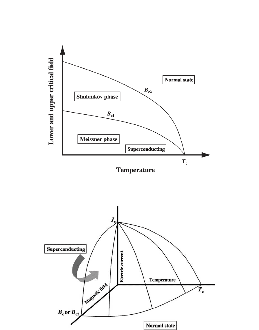
state. The values of B
c1
and B
c2
are also temperature
dependent and decrease with increasing temperature.
At T
c
both values, B
c1
and B
c2
, are zero (Fig. 5).
3. Critical Current Density
Both categories of superconductors, Types 1 and 2,
can carry large electric currents up to a certain value
which is called the critical current density, J
c
(A cm
2
). Above J
c
, the superconductor becomes
normal conducting. J
c
is dependent on both the tem-
perature and the external magnetic field. At T
c
or B
c
(Type 1) or B
c2
(Type 2) the value of J
c
is zero and the
superconductor becomes normal conducting (Fig. 6).
Superconductors show characteristic current vs. volt-
age behavior. At a current below J
c
the voltage is
zero. Above J
c
, as in a metal, the voltage increases
with the current (Fig. 7).
In the mixed state, when an electric current is
transported through the superconductor due to the
Lorenz force, the trapped flux lines can move through
the superconductor causing dissipation of the current
and a warming of the superconductor. This phenom-
enon can result in a rapid transition into the normal
conducting state. Therefore, the value of J
c
is signi-
ficantly lower in the Shubnikov phase compared to
the Meissner phase. However, the flux lines can be
pinned by so-called pinning centers, which are defects
with different dimensions within the superconductor.
For example, point defects (zero dimension), dislo-
cation lines (one dimension), twin planes (two di-
mensions), and second phases (three dimensions).
The flux lines remain pinned until the Lorenz force
surpasses the pinning force of the defect.
4. Superconducting Materials
Except for the elements vanadium, technetium, and
niobium, the Type 2 category of superconductors in-
cludes compounds and alloys. Niobium (T
c
¼ 9:2 K),
especially when alloyed with titanium (Nb0.7Ti0.3:
T
c
¼ 9:8 K), exhibits the highest critical temperature
of all elements. Although superconductors with higher
Figure 2
Magnetization of a Type 1 superconductor vs. the external field, B
ex
. Insert: Magnetic field within a Type 1
superconductor, B
in
, vs. the external field, B
ex
.
1137
Superconducting Materials, Types of
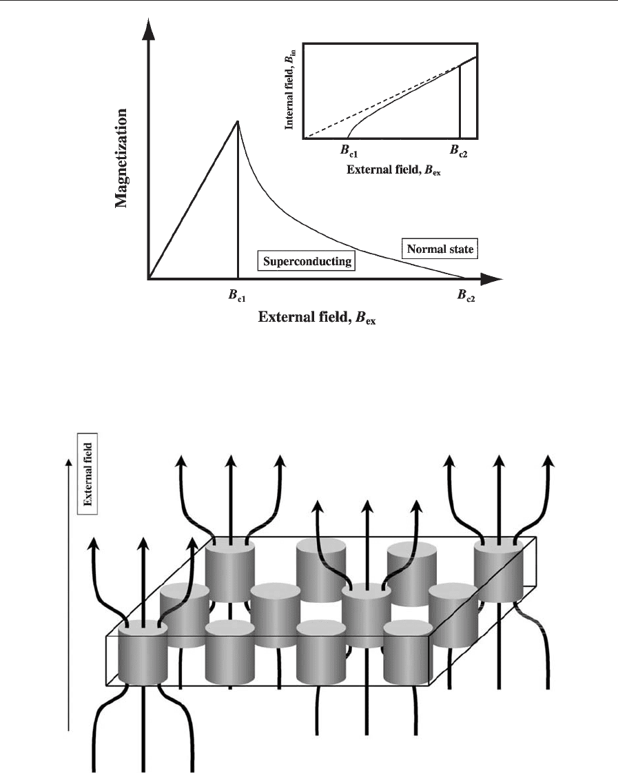
Figure 3
Magnetization of a Type 2 superconductor vs. the external field, B
ex
. Insert: Magnetic field within a Type 2
superconductor, B
in
, vs. the external field, B
ex
.
Figure 4
Type 2 superconductor with trapped flux lines vortex.
1138
Superconducting Materials, Types of
T
c
are available, until now, most commercially avail-
able superconducting magnets operating below about
5 T are based on NbTi wires, due to its compara-
bly low price and excellent manufacturing qualities.
During the late 1940s and early 1950s, compounds
were found with T
c
values in the range of 10–20 K.
These compounds belong to the b-tungsten structure
family, also named A15 phases or A
3
B structure. The
unit cell of the structure consists of a cube with the B
atoms entering each corner of the cube. The A atoms
Figure 5
Lower and upper critical field of a Type 2 superconductor vs. the temperature.
Figure 6
Critical current density, J
c
, vs. the temperature and the external magnetic field.
1139
Superconducting Materials, Types of