Buschow K.H.J. (Ed.) Concise Encyclopedia of Magnetic and Superconducting Materials
Подождите немного. Документ загружается.

above). The large jump in the Mn moment at T
N
leads to a large jump in the volume, and concurrently
to a large thermal hysteresis (E20 K), clearly indi-
cating a first-order transition. For T4T
N
, a large
thermal expansivity is found. This is ascribed to spin
fluctuations in the (paramagnetic) Mn subsystem. On
the basis of a combined analysis of specific-heat data
and thermal-expansion for the related alloying system
(Nd,Lu)Mn
2
, Kim-Ngan et al. (1994) succeeded to
separate the contribution of the spin fluctuations
from the lattice contribution and other, electronic,
contributions (Fig. 6). The excess volume is assumed
to be due to the magnetic Mn moment. When for the
antiferromagnetically ordered Mn-system at low
temperatures the Mn moment is taken as 2.7 m
B
/
Mn, the mean fluctuating Mn moment would be
B2.5 m
B
/Mn at room temperature. So, the fluctuating
Mn moments are quite comparable with local atomic
moments (of fixed magnitude).
See also: Electron Systems: Strong Correlations;
Itinerant Electron Systems: Magnetism (Ferromag-
netism); Magnetoelastic Phenomena; Metamagnet-
ism: Itinerant Electrons
Bibliography
Aguayo A, Mazin I I, Singh D J 2004 Why Ni
3
Al is an itine-
rant ferromagnet but Ni
3
Ga is not. Phys. Rev. Lett. 92,
147201
1–4
Brommer P E, Franse J J M 1990 Strongly enhanced itinerant
intermetallics and alloys. In: Buschow K H J, Wohlfarth E P
(eds.) Ferromagnetic Materials. Elsevier (North-Holland),
Amsterdam, Vol. 5, pp. 323–96
Duc N H, Brommer P E 1999 3D-Moments and spin fluctu-
ations in some rare-earth – cobalt compounds. In: Buschow
K H J (ed.) Handbook of Magnetic Materials. Elsevier,
Amsterdam, vol. 12, pp. 259–394
Jullien R, Be
´
al-Monod M T, Coqblin B 1974 Resistivity of
nearly magnetic metals at high temperatures: Application to
neptunium and plutonium. Phys. Rev. B 9, 1441–57
Kaul S N 1999 Spin fluctuation theory for weak itinerant-elec-
tron ferromagnets: revisited. J. Phys.: Condens. Matter 11,
7597–614
Kim-Ngan N H, Brommer P E, Franse J J M 1994 Spin fluc-
tuations in the (Nd,Lu)Mn
2
system. IEEE Transactions on
Magnetics 30, 866–8
Moriya T 1985 Spin Fluctuations in Itinerant Electron Magnet-
ism. Springer, Berlin
Nakada K, Shimizu H, Yamada H, Harima H 2004 Mag-
netic properties and Fermi surface of YMn
2
. J. Magn. Magn.
Mater. 262, 374–81
Semwal A, Kaul S N 2002 Effect of site disorder on the as-
ymptotic critical behaviour of Ni
75
Al
25
. J. Phys.: Condens.
Matter 14, 5829–47
Shimizu M 1981 Itinerant electron magnetism. Rep. Prog. Phys.
44, 329–409
Takahashi Y 2001 Quantum spin fluctuation theory of the
magnetic equation of state of weak itinerant-electron ferro-
magnets. J. Phys.: Condens. Matter 13, 6323–58
Yamada H, Fukamichi K, Goto T 2003 Recent advances of
itinerant-electron metamagnetism and related properties of
intermetallic compounds. Physica B 327, 148–54
P. E. Brommer
Van der Waals-Zeeman Instituut, Universiteit van
Amsterdam, Amsterdam, The Netherlands
Spin Transitio n Compounds
Octahedral complexes of transition metal ions with
configurations d
4
d
7
exist in either the high-spin
(HS) or low-spin (LS) state, depending on the nature
of the ligand field. In weak fields the ground state is
HS, the d electrons being distributed over the t
2g
and
e
g
sets, whereas strong fields stabilize the LS state, the
t
2g
set being completely occupied before electrons are
added to the e
g
set (Fig. 1). For iron(II), for example,
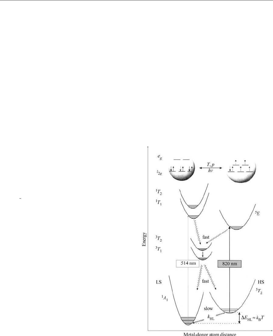
Figure 1
Representation of the interconversion of HS and LS
states for iron(II) and the mechanism of the LIESST
effect.
1100
Spin Transition Compounds

the two states are illustrated by [Fe(H
2
O)
6
]
2 þ
, con-
figuration (t
2g
)
4
(e
g
)
2
, and [Fe(CN)
6
]
4
, configuration
(t
2g
)
6
. For intermediate fields the energy difference
between the lowest vibronic levels of the potential
wells of the two states may be sufficiently small such
that application of some relatively minor external
perturbation effects a change in the state. This phe-
nomenon is known as a spin transition (ST) or spin
crossover. Materials which display STs are of interest
because of their potential in electronic devices for
applications such as data storage and displays. The
first transitions were observed in the 1930s in
iron(III) dithiocarbamates and these were later ex-
tensively studied in the 1960s (Martin and White
1968). Although STs have been observed for all the
configurations d
4
d
7
for the first transition series,
the greatest number has been reported for iron(II)
(Gu
¨
tlich et al. 1994).
1. Occurrence and Detection of Spin Transitions
A change in spin state effects fundamental changes in
the electronic configuration and thus will affect all
those properties of the system which depend on elec-
tronic structure. The most important of these are
magnetism, color, and structure. In HS Fe
II
, electrons
partly occupy both the antibonding e
g
set and the
nonbonding or weakly bonding t
2g
set, whereas in LS
Fe
II
only the t
2g
set is occupied. This allows closer
approach of the donor atoms in the LS state and
hence a HS-LS spin transition is accompanied by a
significant structural change involving a contraction
in the metal–donor atom distances of about 0.2A
˚
or 10%. For solid systems this change in molecular
dimensions may bring about fundamental changes
in the crystal lattice. For this reason STs in solid
systems can follow a number of different paths. These
differ principally in the degree of cooperativity
associated with the transition. When this is low the
transition will be gradual or continuous, but as coop-
erativity increases the transition becomes more
abrupt and may be associated with a phase change
and hysteresis. In some instances two-step transitions
have been observed, while in others residual fractions
of HS or LS species persist at the extremities of the
transition.
An ST may be monitored and an ST curve (HS
fraction vs. T) constructed by a variety of techniques.
The curve reflects the nature of the change in pop-
ulation of the HS state with change in temperature.
For iron(II), Mo
¨
ssbauer spectroscopy is particularly
suitable for characterizing an ST since the spectral
parameters associated with the HS and LS states
clearly differ and the timescale of the technique gen-
erally allows the detection and evaluation of the sep-
arate spin states in the course of the transition.
Although the criterion for the occurrence of an ST
may appear very restrictive, a large number (4150)
of systems have been characterized. The majority are
Fe
II
N
6
systems involving heterocyclic donors. The
first synthetic system, Fe(phen)
2
(NCS)
2
(phen ¼1,10-
phenanthroline), was identified by Ko
¨
nig and Madeja
(1966). Since then many species of similar composi-
tion have been shown to undergo transitions. In ad-
dition, derivatives of simple unidentate ligands such
as isoxazole and tetrazoles, along with multidentate
and polynuclear systems are known. Two strategies
are widely effective in fine-tuning the field strength of
model ligands so as to bring it into the crossover
region:
(i) Incorporation of chemical substituents. If the
substituent is adjacent to a donor atom this will de-
stabilize the singlet state by hindering the close ap-
proach of the metal atom and is illustrated by
[Fe(mephen)
3
]
2 þ
(mephen ¼2-methyl-1,10-phenan-
throline) which is HS at room temperature but
undergoes a transition to LS at low temperatures,
in contrast to the unsubstituted [Fe(phen)
3
]
2 þ
which
is LS. Where the substituent is remote from the donor
atom electronic effects may stabilize either state.
(ii) The replacement of six-membered heterocycles
by five-membered ones. The principal effect here is to
reduce both the s-donor and p-acceptor character of
the system, thus favoring the quintet state, illustrated
by the spin crossover behavior of [Fe(pyim)
3
]
2 þ
(pyim ¼2-(pyridin-2-yl)imidazole), in contrast to the
completely LS nature of [Fe(bpy)
3
]
2 þ
(bpy ¼2,2
0
-
bipyridine).
2. Solution and Solid-state Behavior
STs are observed for systems in both solution and
solid states, though the one system will not necessar-
ily display a transition in both phases. In solution,
interactions between the molecules undergoing spin
change are virtually negligible and thus the course of
the transition can be described by a Boltzmann dis-
tribution over all HS vibronic states and the LS state.
The driving force for the transition is the considerable
entropy gain of B50–80 J mol
1
K
1
for the LS-HS
conversion, made up of a magnetic component,
DS
mag
¼R[ln(2S þ1)
HS
ln(2S þ1)
LS
],
B13 J mol
1
K
1
, and a larger vibrational entropy
contribution arising from the much higher degener-
acies in the HS state. The enthalpy change for the
LS-HS conversion is typically 6–15 kJ mol
1
and
is associated primarily with rearrangement of the co-
ordination sphere (metal–donor atom bond length
increase). In the solid state there is electron–phonon
coupling between the molecules changing spin state,
resulting in cooperative interactions of varying
degrees.
One of the most successful models for ST behavior
takes as its basis the change in the metal–donor
atom distance accompanying a transition (Spiering
and Willenbacher 1989). It is proposed that such a
1101
Spin Transition Compounds

significant change at every ‘‘point defect’’ where an
ST occurs sets up pressure (an ‘‘image pressure’’)
which is communicated to the surroundings via pho-
non interactions. In the course of the ST, at many
point defects the lattice expands and accelerates the
ST in other metal centers. Thus, the nature of
the cooperative interactions in a solid is elastic, and
the model uses typical quantities from elasticity the-
ory, e.g., bulk modulus and Poisson ratio, to account
for the experimental results.
3. Effect of Pressure
The effect of increased pressure is to favor the HS-
LS conversion because of the smaller volume of the
LS form. From both solution studies and crystal
structure determinations, DV has been estimated as
typically 50A
˚
3
per octahedral unit. The study of the
effects of high pressure on the course of STs in solid
samples has revealed some subtle effects which in-
clude displacement of the transition temperature,
change in the width of the hysteresis loop, and
changes in the residual fractions of HS and LS species
at the extremes of the temperature range for the
transition (Ksenofontov et al. 1999).
4. Effect of Light
It has been observed that an Fe
II
spin crossover
compound in the LS state is converted by light into
the metastable HS state with virtually infinite lifetime
at sufficiently low temperatures (Decurtins et al.
1984). This phenomenon became known as the light-
induced excited spin state trapping (LIESST) effect.
Later it was found that the reverse process is also
possible. The mechanism for these photo-switching
processes, a common feature of most Fe
II
spin cross-
over systems, is shown in Fig. 1. Green light is used
for the spin allowed excitation
1
A
1
-
1
T
1
. A fast re-
laxation cascading over two successive intersystem
crossing steps,
1
T
1
-
3
T
1
-
5
T
2
, populates the metast-
able
5
T
2
state. Reverse LIESST is achieved by appli-
cation of red light whereby the
5
T
2
state is excited to
the
5
E state with two subsequent intersystem crossing
processes
5
E-
3
T
1
-
1
A
1
. As demonstrated by Hauser
(1991), photo-switching from LS to HS is also pos-
sible via
1
A
1
-
3
T
1
-
5
T
2
. LIESST can be induced in
spin crossover molecules embedded in polymer films
and in KBr pellets, in addition to solid samples. It is
worth noting that LIESST has also been observed for
the conversion of a HS ground state to a metastable
LS state by red light (Poganiuch et al. 1990).
The effect of light on spin crossover systems is be-
ing pursued vigorously and a number of phenomena
have been reported. These include: light-induced ther-
mal hysteresis (LITH), the effect of raising and low-
ering temperature under constant irradiation (Desaix
et al. 1998); light-perturbed thermal hysteresis
(LPTH), whereby the hysteresis associated with an
ST is shifted to either lower or higher temperatures
under irradiation of different wavelengths (Renz et al.
2000); and ligand-driven light-induced spin crossover
(LD-LISC), whereby irradiation effects a cis–trans
isomerization of the ligand, with subsequent ST at the
Fe
II
center as a consequence of a change in field
strength (Boillot et al. 1999).
5. Applications
The existence of hysteresis is a prerequisite for bista-
bility, which in turn offers the potential for technical
applications of ST systems such as thermal switches
and sensors. Furthermore, the drastic color change
generally accompanying an ST is promising for ap-
plications in displays (Kahn and Launay 1988).
The remarkable changes of ST behavior under ap-
plied pressure can be exploited in pressure sensors for
applications where remote sensing of pressure could
be achieved by a color change in a spin crossover
material. The light-induced switching phenomena de-
scribed above also offer much promise. Data storage
using spin crossover materials, although now limited
to low-temperature regions, may eventually play a
role in holographic devices. Orientational experi-
ments on ‘‘transient grids’’ of a HS/LS lattice have
yielded highly promising refractive index results. The
switching rates in the subnanosecond region at am-
bient temperatures may be a promising basis for op-
tical switches. Patents covering these aspects have
been registered.
6. Future Developments
Research on ST compounds has grown enormously
both from a chemical point of view, allowing the
more-or-less controlled synthesis of new materials
with special properties, and regarding physical char-
acterization using powerful techniques. Aspects which
are the focus of many research groups include:
*
synergism (coupling) of magnetic exchange be-
tween metal centers and ST at the metal atom;
and
*
detailed structural characterization of metasta-
ble states; important findings on the lattice para-
meters of a system in a LIESST-generated metastable
state have emerged and detailed structural studies will
allow greater understanding of light-induced phe-
nomena in general.
See also: Photomagnetism of Molecular Systems
Bibliography
Boillot M-L, Chantraine S, Zarembowitch J, Lallemand J-Y,
Prunet J 1999 First ligand-driven, light-induced spin change
1102
Spin Transition Compounds

at room temperature in a transition-metal molecular com-
pound. New J. Chem. 179–83
Decurtins S, Gu
¨
tlich P, Ko
¨
hler C P, Spiering H, Hauser A 1984
Light-induced excited spin state trapping in a transition metal
complex. Chem. Phys. Lett. 105, 1–4
Desaix A, Robeau O, Jeftic J, Haasnoot J G, Boukheddaden K,
Codjovi E, Linares J, Nogues M, Varret F 1998 Light-in-
duced bistability in spin transition solids leading to thermal
and optical hysteresis. Eur. Phys. J. B6, 183–93
Gu
¨
tlich P, Hauser A, Spiering H 1994 Thermal and optical
switching of iron(II) complexes. Angew. Chem. Int. Ed. Engl.
33, 2024–54
Hauser A 1991 Intersystem crossing in Fe(II) coordination
compounds. Coord. Chem. Rev. 111, 275–90
Kahn O, Launay J P 1988 Molecular bistabilty: an overview.
Chemtronics 3, 140
Ko
¨
nig E, Madeja K 1966 Unusual magnetic behaviour of
some iron(II)–bis(1,10-phenanthroline) complexes. Chem.
Commun. 61
Ksenofontov V, Spiering H, Schreiner A, Levchenko G, Good-
win H A, Gu
¨
tlich P 1999 The influence of hydrostatic pres-
sure on hysteresis phase transition in spin crossover
compounds. J. Phys. Chem. Solids 60, 393–9
Martin R L, White A H 1968 The nature of the transition
between high-spin and low-spin octahedral complexes of the
transition metals. Trans. Met. Chem. 4, 113
Poganiuch P, Decurtins S, Gu
¨
tlich P 1990 Thermal- and light-
induced spin transition in [Fe(mtz)
6
][BF
4
]
2
. First successful
formation of a metastable low-spin state by irradiation with
light at low temperatures. J. Am. Chem. Soc. 112, 3270–8
Renz F, Spiering H, Goodwin H A, Gu
¨
tlich P 2000 Light per-
turbed hysteresis in an iron(II) crossover compound observed
by the Mo
¨
ssbauer effect. Hyperfine Int. in press
Spiering H, Willenbacher N J 1989 Elastic interaction of high-
spin and low-spin complex molecules in spin crossover com-
pounds. J. Phys.: Condens. Matter 1, 10089–105
P. Gu
¨
tlich
Johannes Gutenberg Universita
¨
t, Mainz, Germany
H. A. Goodwin
University of New South Wales, Sydney, Australia
Spintronics in Semiconductor
Nanostructures
Spintronics is a relatively new field of electronics
which has been rapidly developing over the past few
years. In order to understand the potential of this
new kind of electronics, it is useful to consider the
basic properties of the electron. One of these prop-
erties is the charge, which has been exploited up to
now in conventional semiconductor electronics. The
charge of a single electron is constant and local
changes of charge can only happen via a current.
However, the electron also has a second property,
namely the spin. The spin can be seen as an angular
momentum which—corresponding to a rotating
charge—also induces a magnetic moment. Much in
contrast to a macroscopic angular momentum the
spin can only have two different (opposite) directions.
It is quantized, with the axis of quantization given by
an external magnetic field. So, whereas the electron
charge has a constant value, the spin of an electron
can have two different values called spin-up and spin-
down which can be ‘‘flipped’’ from one value to the
other. This property allows for the local creation of a
spin population without a current (in contrast to a
charge) but it also means that a spin population can
vanish over time, while a charge population in the
absence of a current cannot.
A well-known effect based on spin is ferromagnet-
ism. In normal materials the spin of the electrons is
distributed statistically. This means that 50% of the
electrons have spin-up and 50% have spin-down. In
ferromagnetic materials such as Fe, Co, or Ni, it is
energetically favorable for a majority of the elec-
trons to have the same spin direction. In this case the
material exhibits a macroscopic magnetic moment
and produces an external magnetic field. Until the
mid-1980s, access to the magnetic properties was
possible only via the magnetic field, using inductive
pickup coils like in tape storage or computer disk
applications.
In 1987 the situation changed, when a new effect
was discovered. Baibich et al. (1988), Binasch et al.
(1989), and Valet and Fert (1993) discovered that
metallic multilayers (see Multilayers: Interlayer Cou-
pling) composed of magnetic and nonmagnetic metals
can exhibit a so-called giant magnetoresistance (see
Giant Magnetoresistance). When an external magnetic
field is applied to the system, the resistance of the
layers decreases. It was soon thereafter determined
that the effect was based on the spin polarization of
the carriers. The spin polarization of the carriers in a
material b is a macroscopic quantity giving the aver-
age spin population of the electronic system:
b ¼
n
m
n
k
n
m
þ n
k
ð1Þ
where n
m
and n
k
are the number of carriers with
spin-up and spin-down, respectively. It is clearly
visible that for a nonmagnetic material b is 0. In a
conventional ferromagnetic material, its value can be
up to 40%.
If we assume the same mobility for spin-up and
spin-down electrons, without loss of generality, we
can assume
b ¼
r
m
r
k
r
m
þ r
k
ð2Þ
where r is the local conductivity.
In a homogeneous material this spin polarization
can give rise to a spin-polarized current. As long as
spin flips are neglected, we can derive two equations
1103
Spintronics in Semiconductor Nanostructures
for the spin-up and spin-down current, respectively:
~
j
mk
¼
~
Er
mk
ð3Þ
The spin polarization of the currents a is then de-
fined as
a ¼
j
m
j
k
j
m
þ j
k
ð4Þ
This corresponds to a picture in which two spin
channels exist, which can be seen as fully spin-polar-
ized noninteracting resistors. However, it is clear that
the voltage applied to both resistors is always the
same, because the interaction of electrons with an
electric field is independent from spin, and current
contacts are typically not spin selective. A spin-po-
larized current can thus only be obtained in a mate-
rial where the carriers are already spin polarized.
The picture changes dramatically, when hybrid
structures consisting of both spin-polarized and un-
polarized materials are investigated. In this case, the
continuity of the respective spin currents has to be
maintained, unless a strong spin scattering is present.
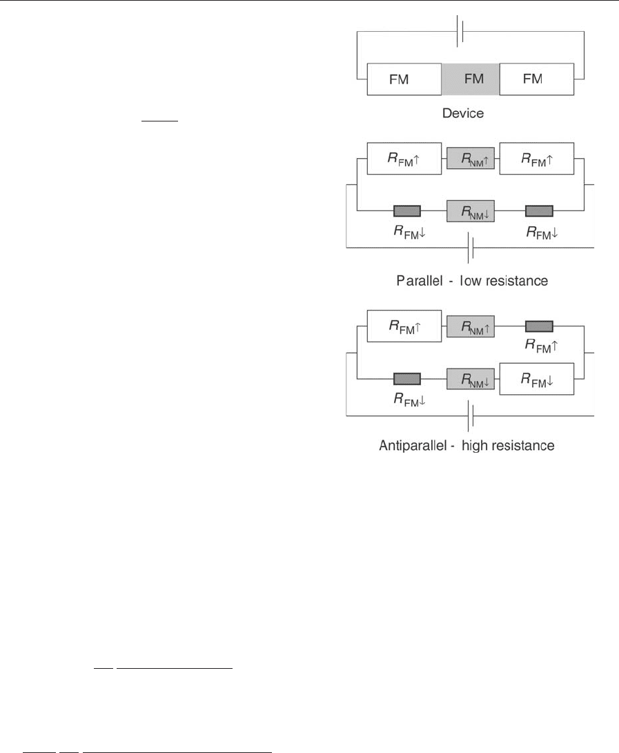
For a ferromagnet/nonmagnet/ferromagnet (FM/
NM/FM) trilayer system this leads to the so-called
two-current model, in which two spin channels are
present. Each channel consists of three resistors, two
for the two ferromagnets and one for the nonmag-
netic material (Fig. 1). When the two magnetic layers
are magnetized in parallel, the two spin channels have
a different total resistance. When the alignment is
antiparallel, the resistances of the spin channels are
equal. Calculating the total resistance of the system
yields different values for parallel and antiparallel
alignment. The value for the parallel alignment is
always lower than for the antiparallel alignment.
This effect is termed giant magnetoresistance (GMR).
Besides the appearance of a magnetoresistance, a
second effect is also present; in the antiparallel state,
the current through both spin channels is equal.
However, in the parallel state, the two spin currents
are different yielding a spin-polarized current in the
nonmagnetic material.
The spin polarization of the current in the parallel
state is equal to
a ¼ b
R
fm
R
sc
2
2ðR
fm
=R
sc
Þþð1 b
2
Þ
ð5Þ
and the normalized difference in resistance between
the parallel and the antiparallel state is
a ¼
b
2
1 b
2
R
2
fm
R
2
sc
2
4ðR
2
fm
=R
2
sc
Þþ2ðR
fm
=R
sc
Þþð1 b
2
Þ
ð6Þ
GMR quickly made its way into applications like
hard-disk read heads and field sensors (see Magnetic
Recording Systems: Spin Valves) and also seemed
desirable for integrating spin-based devices into con-
ventional electronics.
However, in metal-based devices high values for
GMR can only be achieved when the thickness of the
nonmagnetic material is only a few A
˚
, a fact which
limits the device resistance to fractions of an O and is
incompatible with existing CMOS technology. Fur-
thermore, these small dimensions leave no room for
the manipulation of the spin. Indeed in 1990 a new
concept for a semiconductor device for spin manip-
ulation was published by Datta and Das in which a
spin-polarized current through a semiconductor can
be modulated by an electrostatic gate via the spin-
orbit coupling. This device has come to be known as
Figure 1
Resistor model (two-current model) for the
semiconductor device with two ferromagnetic contacts
(up), showing the configuration of the parallel and of the
antiparallel magnetization of the contacts. The depicted
size of the resistors indicates the higher and lower
resistance of spin-up and spin-down channel,
respectively. A straightforward calculation shows that
the total resistance in the parallel configuration is lower
than in the antiparallel case.
1104
Spintronics in Semiconductor Nanostructures

the Datta-transistor (Datta and Das 1990). The au-
thors claimed that the spin-polarized current should
be obtained by using a GMR-like geometry with
ferromagnetic metal contacts on a semiconductor
mesa. Furthermore, optical experiments indicated
that extremely long spin lifetimes and large spin-flip
lengths can be obtained in semiconductors (Kikkawa
and Awschalom 1999). Motivated by these results
several research groups for more than half a decade
tried to achieve the injection of a spin-polarized cur-
rent (spin injection) into a semiconductor, however,
without any results that could not be interpreted as
side effects like magnetoresistance or Hall effect
(Monzon and Roukes 1999).
The explanation for this failure is simple. If we
replace the nonmagnetic metal in the GMR config-
uration (Fig. 1) by a semiconductor, it seems on first
sight that the picture does not change. However, us-
ing real numbers for the resistance values shows that
in comparison to the resistance of the semiconductor,
the resistance of the ferromagnet can be neglected.
Even when the spin polarization of the ferromagnet is
80% or 90%, the difference in resistance of both spin
channels will be too low to induce any difference in
the current of the two spin channels, and any current
through the semiconductor remains unpolarized.
In Eqn. (5) this corresponds to R
fm
{R
sc
. This
problem was first discussed in Schmidt et al. (2000)
where the calculation was extended to a local de-
scription, in which spin flips in the ferromagnetic
material are taken into account. In this case, the out-
come is similar, only the resistance R
fm
is replaced by
l
fm
=s
fm
which is the resistance of a sheet of the
ferromagnet with the thickness of the spin-flip length.
The spin polarization of the current in the semicon-
ductor is thus proportional to the spin polarization of
the ferromagnet b; however, it is reduced by a factor
of ðl
fm
=s
fm
Þ=ðx
0
=s
sc
Þ where x
0
and s
sc
are the length
and conductivity of the semiconductor, respectively.
It seems obvious that one way to circumvent this
conductance mismatch is to increase the value of
l
fm
=s
fm
; however, ferromagnetic materials typically
have a small spin-flip length and an extremely high
resistivity would be needed, which will deteriorate the
electrical properties of a device. One way to achieve
such a high resistance contact has been discussed by
Rashba (2000) and by Fert et al. (2001). Less obvious
is the use of fully spin-polarized materials (see Half-
metallic Magnetism) with b ¼1. In this limit we ob-
tain a ¼1 independent from the resistivity and the
spin-flip length in the materials. This is possible be-
cause one of the spin channels is now completely
blocked due to the absence of carriers.
Approximately at the same time as the conduct-
ance mismatch was identified, new experiments based
on a different class of magnetic materials were
published. When semiconductors are doped with
magnetic ions (e.g., Mn or Fe), they can become
ferromagnetic or strongly paramagnetic (see Dilute
Magnetic Semiconductors). ZnMnSe is an example of
these so-called dilute magnetic semiconductors
(DMSs). Without external magnetic fields, the Mn-
spins are not aligned or are antiferromagnetically
coupled. However, at low temperatures and in an
external magnetic field the material exhibits a giant
Zeeman splitting. The g-factor can be larger than 100,
leading to a splitting of the conduction band of up to
20 meV. At low temperatures, where kT is smaller
than the Zeeman splitting, the population of the two
spin levels can be expressed by a Boltzmann factor.
The upper spin level is thus completely depopulated
and the material should act as a perfect spin aligning
contact.
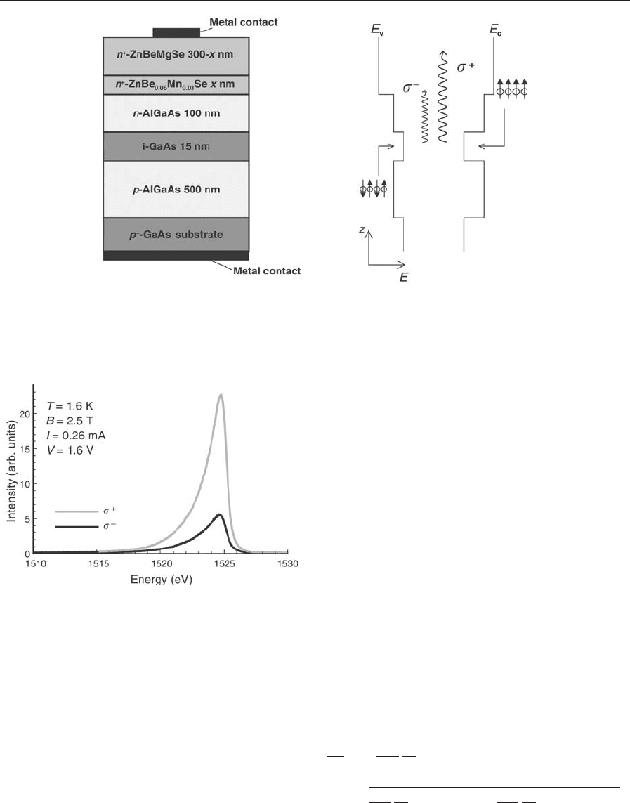
The first proof of high-efficiency spin injection us-
ing dilute magnetic semiconductors was obtained in
1999 using a light emitting diode (LED) fitted with a
DMS contact. When an electron and a hole recom-
bine in GaAs and emit a photon, the polarization of
this photon is related to the spins of the hole and the
electron via the quantum mechanical selection rules.
When unpolarized holes recombine with spin-polar-
ized electrons, there are two possibilities. In case light
and heavy holes are degenerate, the circular optical
polarization of the emitted photons is
P
opt
circ
¼
s
þ
s
s
þ
þ s
¼
ð3n
m
þ n
k
Þð3n
k
þ n
m
Þ
ð3n
m
þ n
k
Þþð3n
k
þ n
m
Þ
¼
1
2
n
m
n
k
n
m
þ n
k
¼
1
2
a ð7Þ
When the degeneracy is lifted the circular optical
polarization is equal to the electron spin polarization.
A GaAs LED which is fed with unpolarized holes
from the p-side and with spin-polarized electrons
from the n-side will thus emit light with a circular
polarization which is directly proportional to the
electron spin polarization. Such a diode was fabri-
cated (Fig. 2) and characterized at low temperature
and in moderate magnetic fields between 0 T and 5 T.
The hole confinement in the diode was weak in order
to insure degenerate hole states. Figure 3 shows a
typical electroluminescence (EL) spectrum of a spin
LED. The maximum polarization obtained in the
experiment was up to 46% indicating an electron spin
polarization of more than 90% (Fiederling et al.
1999). A similar experiment was performed using
ferromagnetic GaMnAs, however, with a strongly
reduced efficiency (Ohno et al. 1999).
When DMSs are used as spin aligners however,
electrical detection of spin-polarized transport is
more difficult than for ferromagnets. The paramag-
netic behavior makes it virtually impossible to
achieve two small contacts with antiparallel magnet-
ization and thus excludes GMR-like experiments. In
addition, the magnitude of magnetoresistance effects
due to spin injection is typically proportional to the
square of the spin injection efficiency (Eqn. (6)).
1105
Spintronics in Semiconductor Nanostructures
While the latter would not present too big a problem
due to the high spin injection efficiency demonstrated
in the optical experiment, the realization of GMR
could only be achieved using very small contacts with
small ferromagnetic bias magnets that are difficult to
realize.
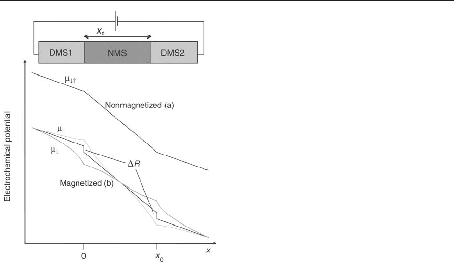
However, the splitting of the electrochemical
potentials which is always present in spin injection
experiments can be used in electrical detection of
the spin injection effect. When a nonmagnetic semi-
conductor is fitted with two dilute magnetic semi-
conductor contacts and a voltage is applied, a new
magnetoresistance effect can be observed. While the
DMS is not magnetized, current through the sample
will lead to an identical slope for the electrochemical
potentials of spin-up and spin-down electrons in the
nonmagnetic semiconductor (NMS) (Fig. 4(a)). As
soon as the DMS is magnetized, the electrochemical
potentials will split at the interfaces leading to a kind
of boundary resistance (Fig. 4(b)).
Much in contrast to giant magnetoresistance, this
boundary resistance persists even if the spacing be-
tween the contacts is larger than the spin-flip length
in the NMS (the effect can also be present in a single
contact geometry). This boundary resistance will ap-
pear as a magnetoresistance, which can be up to
100% of the resistance of the NMS. The increase of
the resistance can be attributed to the nonequilibrium
distribution of spin currents in the spin channels of
the NMS. At the boundary, one spin channel is sup-
pressed over the range of the spin-flip length, reduc-
ing the total conductivity. In the ideal case of full spin
polarization and no spin scattering, one spin channel
is completely suppressed throughout the NMS lead-
ing to a reduction of the conductivity by a factor of 2.
For a finite spacing of the contacts, the magnetore-
sistance can be shown to be
DR
R
sc
¼ b
2
l
dms
s
dms
s
sc
x
0
2
l
dms
s
dms
s
sc
l
sc
ð1 þ e
x
0
=l
sc
Þþ2
l
dms
s
dms
s
sc
x
0
e
x
0
=l
sc
þ 1 b
2
ð8Þ
Figure 2
Layer sequence (left) and band structure (right) of the spin aligner LED. The device consists of a GaAs/AlGaAs LED
which has a spin aligning n-contact. The electrons are aligned in the II–VI-layer and recombine in the GaAs with
unpolarized holes coming from the GaAs substrate.
Figure 3
EL spectrum of a typical spin LED. The signal is
strongly polarized.
1106
Spintronics in Semiconductor Nanostructures
The effect has been observed experimentally in an
all II–VI semiconductor structure where the NMS
was ZnBeSe and the DMS was ZnBeMnSe. The ob-
served effect was up to 25% of the total device re-
sistance (Schmidt et al. 2001). The deviation from
100% can be explained by the fact that the contact
spacing in this experiment was much larger than the
expected spin scattering length in ZnBeSe.
Meanwhile, different experiments using optical de-
tection and based on ferromagnetic metal contacts
with tunnel barriers have been published (Motsnyi
et al. 2002, Zhu et al. 2001). Although the efficiency
obtained is not as high as in the case of DMS con-
tacts, they show that based on a detailed understand-
ing of the phenomena, novel approaches can lead
towards room-temperature applications. In addition,
over the past years a large research effort has been
initiated and is ongoing which is dedicated to highly
spin-polarized materials that are ferromagnetic at
room temperature. These could replace DMSs and
still maintain the same spin injection efficiency that is
needed for device applications.
Bibliography
Baibich M N, Broto J M, Fert A 1988 Giant magnetoresistance
of (001)Fe/(001)Cr magnetic superlattices. Phys. Rev. Lett.
61, 2472
Binasch G, Gru
¨
nberg P, Saurenbach F, Zinn W 1989 Enhanced
magnetoresistance in layered structures with antiferromag-
netic interlayer exchange. Phys. Rev. B 39, 4828
Datta S, Das B 1990 Electronic analog of the electrooptic
modulator. Appl. Phys. Lett. 56 (7), 665
Fert A, Jaffres H 2001 Conditions for efficient spin injection
from a ferromagnetic metal into a semiconductor. Phys. Rev.
B 64, 184420
Fiederling R, Keim M, Reuscher G, Ossau W, Schmidt G,
Waag A, Molenkamp L W 1999 Injection and detection of a
spin-polarized current in a light-emitting diode. Nature
(London) 402, 787
Kikkawa J M, Awschalom D D 1999 Lateral drag of spin co-
herence in gallium arsenide. Nature 397, 139–41
Monzon F G, Roukes M L 1999 Spin injection and the local
Hall effect in InAs quantum wells. JMMM 198–199, 632
Motsnyi V F, De Boeck J, Das J, Van Roy W, Borghs G,
Goovaerts E, Safarov V I 2002 Electrical spin injection in a
ferromagnet/tunnel barrier/semiconductor heterostructure.
Appl. Phys. Lett. 81 (2), 265
Ohno Y, Young D K, Beschoten B, Matsukura F, Ohno H,
Awschalom D D 1999 Electrical spin injection in a ferro-
magnetic semiconductor heterostructure. Nature 402, 790
Rashba E I 2000 Theory of electrical spin injection: tunnel
contacts as a solution of the conductivity mismatch problem.
Phys. Rev. B 62, R16267
Schmidt G, Ferrand D, Molenkamp L W, Filip A T, van Wees
B J 2000 Fundamental obstacle for electrical spin injection
from a ferromagnetic metal into a diffusive semiconductor.
Phys. Rev. B 62, R4790
Schmidt G, Richter G, Grabs P, Gould C, Ferrand D, Mole-
nkamp L W 2001 Large magnetoresistance effect due to spin
injection into a nonmagnetic semiconductor. Phys. Rev. Lett.
87, 227203
Valet T, Fert A 1993 Theory of the perpendicular magnetore-
sistance in magnetic multilayers. Phys. Rev. B 48 (10), 7099
Zhu H J, Ramsteiner M, Kostial H, Wassermeier M, Schonherr
H P, Ploog K H 2001 Room-temperature spin injection from
Fe into GaAs. Phys. Rev. Lett. 87 (1), 016601
G. Schmidt
Universita
¨
tWu
¨
rzburg, Germany
SQUIDs: Amplifiers
Radio-frequency (RF) amplifiers virtually always
involve semiconductors as active elements. Noise
temperatures of about 2 K can be achieved with these
devices at frequencies of several hundred megahertz
(Bradley 1999), when the amplifier is cooled to liquid
helium temperatures. Cooling the amplifier to still
lower temperatures does not reduce the noise tem-
perature further because of intrinsic noise sources in
Figure 4
Schematic drawing of the device with two DMS contacts
and plot of the electrochemical potentials for the two
spin channels. Without applied magnetic field (a) the
potentials are identical. As soon as a magnetic field is
applied (b) the potentials split at the interfaces.
1107
SQUIDs: Amplifiers

the transistor. It is also questionable whether a
transistor can be cooled to, say, 1 K because of the
relatively large power dissipation.
At least at frequencies of several hundred mega-
hertz, better results can be obtained by using a
d.c. superconducting quantum interference device
(SQUID) as an RF amplifier. For this device, the
noise temperature continues to decrease linearly with
the bath temperature as it is lowered to about 0.1 K
(Wellstood et al. 1994). This is because the power
dissipation in the SQUID is orders of magnitude
lower than for a transistor, and because the only in-
trinsic noise source at frequencies above a few hertz is
Nyquist noise in the shunts of the junctions.
1. Conventional d.c. SQUID Amplifier
The conventional d.c. SQUID amplifier (Hilbert and
Clarke 1985) consists of two resistively shunted Jose-
phson junctions (see Josephson Junctions: Low-T
c
,
Josephson Junctions: High-T
c
) incorporated into a
square washer of inductance L over which is depos-
ited a superconducting input coil of n turns with in-
ductance L
i
En
2
L. The SQUID is current and flux
biased so that the flux to voltage transfer function,
V
F
¼@V/@F, is close to a maximum. A signal current
I
i
in the input coil generates a flux M
i
I
i
in the SQUID
and an output voltage V
0
EM
i
I
i
V
F
across it, where
M
i
is the mutual inductance between the input coil
and the SQUID. With sufficiently large M
i
and V
F
,a
relatively high gain can be obtained in this configu-
ration. The conventional flux locked loop operation
of the SQUID, which is used to linearize its transfer
function, cannot be realized for the required high-
frequency operation. This means that the amplitude
of the input signal is limited to currents that produce
flux changes in the SQUID of less than about F
0
/4.
Fortunately, in most high-frequency applications the
input signal amplitude is much less than that. If
a SQUID with a flux noise of 10
6
F
0
Hz
1/2
is
used one can still achieve a dynamic range of nearly
120 dBHz
1/2
. Larger flux changes, caused, for ex-
ample, by 50 Hz or 60 Hz fields, can easily be com-
pensated by operating the SQUID in a slow flux
locked loop, which maintains the flux bias at odd
multiples of F
0
/4.
Using a SQUID amplifier with an input circuit
tuned to 93 MHz, Hilbert and Clarke (1985) achieved
a gain of about 18 dB and a noise temperature of
about 1.5 K for a bath temperature of 4.2 K. Above
100 MHz, however, parasitic capacitance, C
p
, be-
tween the input coil of inductance L
i
and the SQUID
produces self-resonances and severely reduces the
gain. The L
i
C
p
parallel resonance can be moved to
higher frequencies by reducing the number of turns,
reducing their width, or increasing the thickness of
the insulating layer that separates the coil from the
SQUID. However, reducing the number of turns may
reduce the mutual inductance between the coil and
the SQUID to a value that is too small to produce a
satisfactory gain. For the same reason the size of the
SQUID hole should be made as large as possible
(e.g., 200 mm 200 mm).
Takami et al. (1989) have described a SQUID am-
plifier in which the input circuit is tuned to the desired
resonant frequency by adjusting the thickness of the
insulating layer between the SQUID and coil, thus
varying the parasitic capacitance. To match the high
resistance of the parallel L
i
C
p
circuit to the 50 O signal
source, the signal is coupled to the coil by a small
(3 pF) capacitor. This scheme leads to a relatively high
quality factor, Q,oftheL
i
C
p
circuit, a high input cur-
rent at the resonant frequency, and thus a high gain.
Gains have been measured of up to 23 dB at 150 MHz,
and a noise temperature of about 0.7 K for a bath
temperature of 4.2 K. Unfortunately, the high Q of the
resonant circuit decreases the bandwidth to about 1%
of the operating frequency, which for many applica-
tions is too small. Increasing the bandwidth by de-
creasing Q decreases the gain. Nevertheless, for
narrow-band applications such as NMR, this coupling
scheme provides a high gain, low noise amplifier for
frequencies of up to a few hundred megahertz.
If operation at higher frequencies is required, the
parasitic capacitance either has to be reduced or
its influence removed with a resonance technique.
Reducing the capacitance can be achieved by placing
the input coil inside the SQUID hole. Because of the
decreased coupling between coil and SQUID, how-
ever, the gain is quite small. Tarasov et al. (1995)
have made a SQUID amplifier in this way, and
reported gains of 8 dB at 700 MHz and a noise tem-
perature of about 1.5 K. In an alternative design,
Prokopenko et al. (1999) used a SQUID amplifier
with a series resonant input circuit to achieve a gain
of 10 dB at 3.8 GHz and a noise temperature of 5 K.
2. SQUID Amplifier with Microstrip Input
Coupling
An alternative way of achieving high gains and low
noise temperatures at high frequencies is to take ad-
vantage of the parasitic capacitance, by operating the
input coil of a d.c. SQUID as a microstrip resonator.
The input signal is no longer coupled to the two ends
of the input coil, but rather between one end of the
coil and the SQUID loop, which acts as a ground
plane for the coil; the other end of the coil is left
open. The microstrip resonator is thus formed by the
inductance of the input coil and its ground plane and
the capacitance between them. In this configuration,
the parasitic capacitance no longer prevents currents
from flowing through the coil.
For the case in which the impedance, Z
s
, of the
source coupled to one end of the microstrip is larger
than its characteristic impedance, Z
0
, and the other
1108
SQUIDs: Amplifiers

end of the input coil is left open, the fundamental
resonance occurs when the length, l, of the microstrip
is equal to half the wavelength of the RF signal. In
this mode, the microstrip resonator is analogous to a
parallel tuned circuit and, neglecting losses in the
microstrip and the SQUID, one calculates a quality
factor Q ¼pZ
s
/2Z
0
. At the resonant frequency the
current fed into the resonator is amplified by Q, pro-
ducing a magnetic flux that is coupled into the
SQUID via a mutual inductance M
s
¼a(LL
s
)
1/2
,
where L
s
is the microstrip inductance and a the cou-
pling coefficient. One selects the resonant frequency
by appropriate choice of the length of the coil. Q,
which determines the bandwidth of the amplifier, can
be varied by selecting the characteristic impedance of
the microstrip; i.e., by choosing an appropriate width
of the turns of the coil and thickness and dielectric
constant of the insulating layer between the coil and
SQUID. One has to keep in mind, however, that re-
ducing Q will increase the bandwidth and lower the
gain, since the resonant current amplification is pro-
portional to Q.
Since the conventional washer SQUID is an asym-
metric device (the two Josephson junctions are situ-
ated close together rather than on opposite sides of
the SQUID loop), one can either ground the washer
or ground the counter electrode close to the Joseph-
son junctions. Using the washer as ground plane for
the input coil suggests one should ground the washer.
However, it is also possible to ground the counter
electrode and have the washer at output potential. In
this case, depending on the sign of V
F
(which deter-
mines the phase shift between input and output of the
amplifier), one can obtain either a negative or positive
feedback from the output to the input, and using
positive feedback, the gain of such amplifiers can be
enhanced substantially.
Using this configuration, Mu
¨
ck et al. (1998) meas-
ured gains of 20 dB up to a frequency of 1.3 GHz.
Noise temperatures as low as 100 mK (at 400 MHz)
have been measured when the SQUID is cooled to
0.4 K (Andre
´
et al. 1999). This noise temperature is
only about a factor of three above the quantum limit.
The intrinsic noise temperature of the amplifier is typ-
ically 1/4 of the bath temperature, T,and,within
measurement errors, scales with T.
The microstrip amplifier can be tuned by means of
a varactor diode, which is connected to the open end
of the microstrip. Changing the capacitance of the
varactor diode by an applied d.c. voltage enables one
to reduce the resonant frequency of the amplifier by
nearly a factor of two. If gains higher than 20 dB are
desired, two amplifiers can be connected in cascade.
3. Conclusion
For applications requiring extremely low noise tem-
peratures at frequencies of several hundred megahertz
and above, an RF amplifier based on a d.c. SQUID is
a promising alternative to semiconductor amplifiers.
Such applications include intermediate frequency am-
plifiers for superconductor–insulator–superconductor
(SIS) mixers, NMR, or Axion detectors. Gains of
more than 20 dB at frequencies exceeding 1 GHz have
been obtained with such amplifiers and noise temper-
atures as low as 100 mK. An exciting possibility is the
expectation that the quantum limit could be reached
with a d.c. SQUID amplifier cooled to about 100 mK.
A challenge for future work is the extension to higher
frequencies. It should be possible to operate a SQUID
amplifier at frequencies exceeding 10 GHz, probably
by modifying the geometry of the SQUID from the
square washer format to, perhaps, an in-line config-
uration. One may hope that the design and testing of
such SQUID amplifiers will be undertaken in the not-
too-distant future.
See also: SQUIDs: The Instrument
Bibliography
Andre
´
M -O, Mu
¨
ck M, Clarke J, Gail J, Heiden C 1999 Mi-
crostrip d.c. SQUID radio frequency amplifier with tenth-
kelvin noise temperature. Appl. Phys. Lett. 75, 698–700
Bradley R F 1999 Cryogenic, low noise, balanced amplifiers for
the 300–1200 MHz band using heterostructure field-effect
transistors. Nucl. Phys. B (Proc. Suppl.) 72,137–44
Hilbert C, Clarke J 1985 DC SQUIDs as radio frequency am-
plifiers. J. Low Temp. Phys. 61, 263–80
Mu
¨
ck M, Andre
´
M -O, Clarke J, Gail J, Heiden C 1998 Radio
frequency amplifier based on a niobium d.c. SQUID with
microstrip input coupling. Appl. Phys. Lett. 72, 2885–7
Prokopenko G V, Balashov D M, Shitov S V, Koshelets V P,
Mygind J 1999 Two-stage S-band d.c. SQUID amplifier.
IEEE Trans. Appl. Supercond. AS-9, in press
Takami T, Noguchi T, Hamanaka H 1989 A d.c. SQUID r.f.
amplifier. IEEE Trans. Mag MAG-25, 1030–3
Tarasov M A, Prokopenko G V, Koshelets V P, Lapitskaya I L,
Filippenko L V 1995 Integrated r.f. amplifier based on d.c.
SQUID. IEEE Trans. Appl. Supercond. AS-5, 3226–9
Wellstood F C, Urbina C, Clarke J 1994 Hot-electron effects in
metals. Phys. Rev. B 49, 5942–55
M. Mu
¨
ck
Institut fu
¨
r Angewandte Physik der Justus-Liebig-
Universita
¨
t Giessen, Germany
SQUIDs: Biomedical Applications
A major application of SQUID systems (see
SQUIDs: The Instrument) is in biomagnetism, a dis-
cipline where the faint magnetic fields associated with
electrophysiological functions of the heart, brain,
nerves, or muscles are detected with the ultrahigh
field sensitivity of SQUIDs. Biomedical investigations
1109
SQUIDs: Biomedical Applications