Bryan L. Programmable controllers. Theory and implementation
Подождите немного. Документ загружается.


INSTALLATION AND
START-UP
SECTION SIX
• PLC Start-Up and Maintenance
• System Selection Guidelines
Industrial Text & Video Company 1-800-752-8398
www.industrialtext.com
Industrial Text & Video Company 1-800-752-8398
www.industrialtext.com
This page intentionally left blank.

PLC START-UP
AND MAINTENANCE
CHAPTER
TWENTY
If I had been present at the Creation, I would
have given some useful hints for the better
arrangement of the Universe.
—Alfonso the Wise, King of Castille
Industrial Text & Video Company 1-800-752-8398
www.industrialtext.com

922
SECTION
6
Installation
and Start-Up
Industrial Text & Video Company 1-800-752-8398
www.industrialtext.com
CHAPTER
20
PLC Start-Up
and Maintenance
The design of programmable controllers includes a number of rugged
features that allow PLCs to be installed in almost any industrial environ-
ment. Although programmable controllers are tough machines, a little fore-
sight during their installation will ensure proper system operation. In this
chapter, we will explore PLC installation, explaining the specifications for
proper PLC component placement and environment. We will also explain
other factors that affect PLC operation, such as noise, heat, and voltage. In
addition, we will discuss wiring guidelines and safety precautions. Although
proper PLC installation leads to good system operation, no programmable
controller system is without faults. Therefore, we will investigate proactive
maintenance techniques, as well as reactive troubleshooting processes. When
you finish this chapter, you will understand the fundamentals of PLC start-up
and operation.
20-1 PLC SYSTEM LAYOUT
PANEL ENCLOSURES AND SYSTEM COMPONENTS
PLCs are generally placed in a NEMA-12 panel enclosure or another type
of NEMA enclosure, depending on the application. A panel enclosure holds
the PLC hardware, protecting it from environmental hazards. Table 20-1
describes the different types of NEMA enclosures. The enclosure size
depends on the total space required. Mounting the controller components in
System layout is the conscientious approach to placing and interconnecting
components not only to satisfy the application, but also to ensure that the
controller will operate trouble free in its environment. In addition to program-
mable controller equipment, the system layout also encompasses the other
components that form the total system. These components include isolation
transformers, auxiliary power supplies, safety control relays, and incoming
line noise suppressors. In a carefully constructed layout, these components
are easy to access and maintain.
PLCs are designed to work on a factory floor; thus, they can withstand harsh
environments. Nevertheless, careful installation planning can increase sys-
tem productivity and decrease maintenance problems. The best location for
a programmable controller is near the machine or process that it will control,
as long as temperature, humidity, and electrical noise are not problems.
Placing the controller near the equipment and using remote I/O where
possible will minimize wire runs and simplify start-up and maintenance.
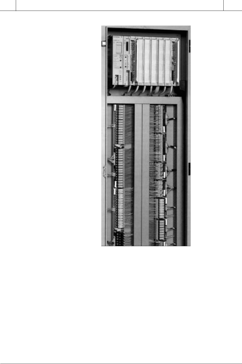
Figure 20-1 shows a programmable controller installation and its wiring
connections.
CHAPTER
HIGHLIGHTS
923
CHAPTER
20
PLC Start-Up
and Maintenance
SECTION
6
Installation
and Start-Up
Industrial Text & Video Company 1-800-752-8398
www.industrialtext.com
Figure 20-1. Installation of a PLC-based system using modular I/O terminal blocks.
an enclosure is not always required, but it is recommended for most applica-
tions to protect the components from atmospheric contaminants, such as
conductive dust, moisture, and other corrosive and harmful airborne sub-
stances. Metal enclosures also help minimize the effects of electromagnetic
radiation, which may be generated by surrounding equipment.
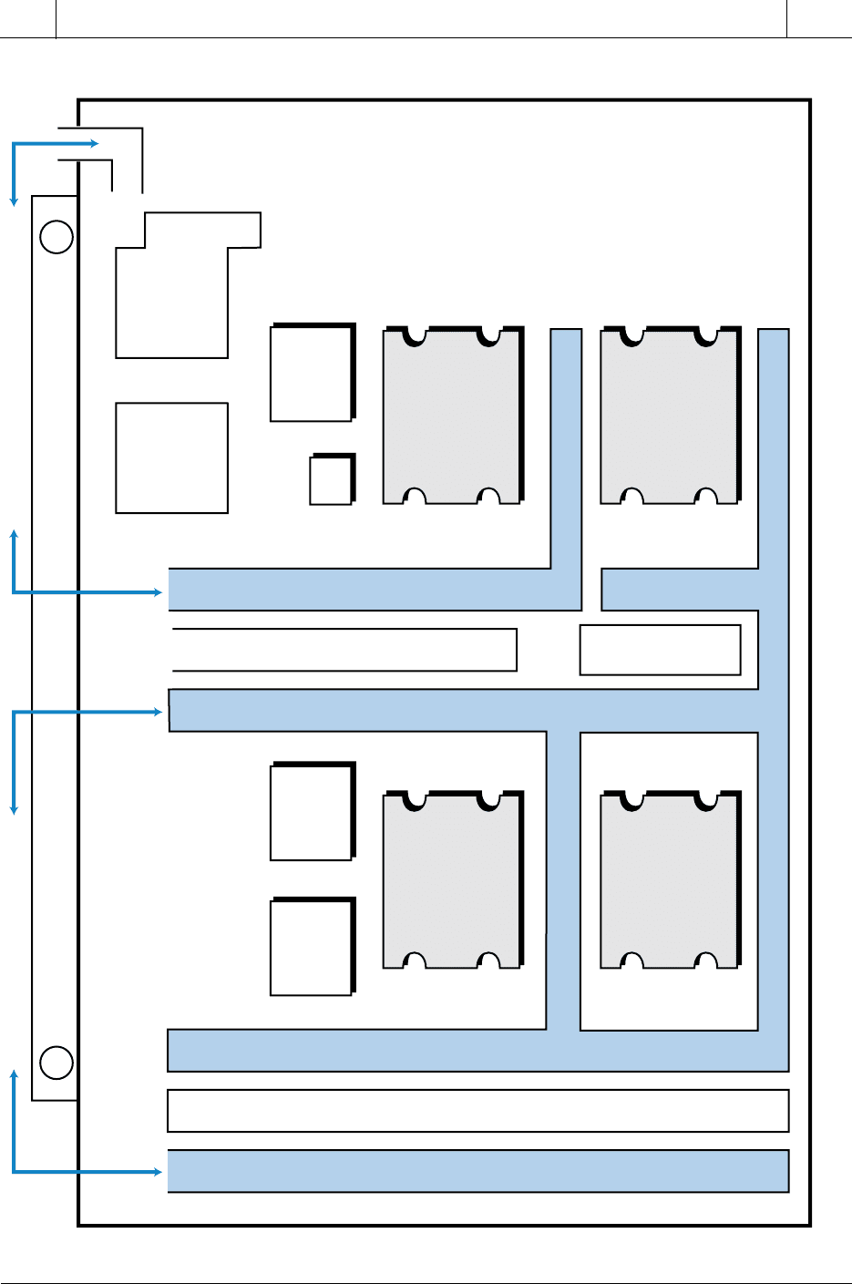
The enclosure layout should conform to NEMA standards, and component
placement and wiring should take into consideration the effects of heat,
electrical noise, vibration, maintenance, and safety. Figure 20-2 illustrates a
typical enclosure layout, which can be used for reference during the following
layout guideline discussion.
Courtesy of Siemens, Alpharetta, GA, and Phoenix Contact, Harrisburg, PA

924
SECTION
6
Installation
and Start-Up
Industrial Text & Video Company 1-800-752-8398
www.industrialtext.com
CHAPTER
20
PLC Start-Up
and Maintenance
Table 20-1. NEMA panel enclosure descriptions.
serusolcnElenaPAMEN
)tnuomecafruS(1epyT
nitnempiuqedesolcneehthtiwtcatnoctsniagatcetorpotesuroodniroF
tsixetonodsnoitidnocecivreslausunuerehwsnoitacilppa
)tnuomhsulF(1epyT
detnuom-ecafrus1epyTsasnoitacilppafosepytemasehtrofdesU
llawretsalproemarfenihcamaninoitallatsnierehwsnoitautisniserusolcne
derisedsi
3epyT
lanretxedna,teels,niar,tsudnwolbdniwtsniagatcetorpotesuroodtuoroF
noitamrofeci
R3epyT
ecilanretxedna,teels,niargnillaftsniagatcetorpotesuroodtuoroF
noitamrof
)snoitacolsuodrazahroferusolcnekcolinU(9dna,7,R3epyT
serusolcne9dna,7,R3epyTsasnoitacilppafosepytemasehtrofdesU
gnisuohdetamorhc-eznorb,munimulaeerf-reppocasedivorptub
4epyT
,niardnatsudnwolbdniwtsniagatcetorpotesuroodtuororoodniroF
retawdetcerid-esohdna,retawgnihsalps
)retseylopdecrofnier-ssalgrebif,tnatsiser-noisorroc,cillatemnoN(X4epyT
dnatsudnwolbdniw,noisorroctsniagatcetorpotesuroodtuodnaroodniroF
retawdetcerid-esohdna,retawgnihsalps,niar
P6epyT
gnirudretawfoyrtneehttsniagatcetorpotesuroodtuodnaroodniroF
htpeddetimilatanoisrembusdegnolorp
)erusolcnedetlobsnoitacolsagsuodrazaH(7epyT
foelbapac;sesagsuodrazahgnisusnoitacilppaniesuroodniroF
nahcusgniniatnocdnasesagdeificepsfonoisolpxelanretninagnidnatshtiw
erehpsomtagnidnuorrusehtfonoitingiehttneverpotnoisolpxe
)snoitacoltsudsuodrazaH(9epyT
otdengised;tneserpsitsudsuodrazaherehwsnoitacilppaniesuroodniroF
desolcneybtsudfonoitingiehttneverpsallewsatsudfoyrtneehttibihorp
secivedgnitareneg-taeh
21epyT
evisorrocnongnippirddna,tridgnillaf,tsudtsniagatcetorpotesuroodniroF
sdiuqil
31epyT
dna,lio,retawfogniyarps,tsudtsniagatcetorpotesuroodniroF
stnaloocevisorrocnon
925
CHAPTER
20
PLC Start-Up
and Maintenance
SECTION
6
Installation
and Start-Up
Industrial Text & Video Company 1-800-752-8398
www.industrialtext.com
Figure 20-2. Enclosure layout.
Input Signal Wireway
Terminal Block (AC Inputs)
Terminal Block (DC I/O)
System Signal Wireway (Inputs)
System/Output Wireway (DC)
I/O Rack
(AC Inputs)
CPU
(AC Inputs)
I/O Rack
(AC Outputs)
I/O Rack
(DC I/O)
PLC
Power
Supply
Auxiliary
Power
Supply
Auxiliary
Power
Supply
2 KVA
Isolation
Transformer
40 Amp
Disconnect
SCR
Terminal Block
AC Outputs
Input Wiring DC Wiring Power WiringOutput Wiring
Output Signal Wireway

926
SECTION
6
Installation
and Start-Up
Industrial Text & Video Company 1-800-752-8398
www.industrialtext.com
CHAPTER
20
PLC Start-Up
and Maintenance
General. The following recommendations address preliminary consider-
ations for the location and physical aspects of a PLC enclosure:
• The enclosure should be located so that the doors can fully open for
easy access when testing or troubleshooting wiring and components.
• The enclosure depth should provide adequate clearance between the
closed enclosure door (including any print pockets mounted on the
door) and the enclosed components and related cables.
• The enclosure’s back panel should be removable to facilitate mount-
ing of the components and other assemblies.
• The cabinet should contain an emergency disconnect device installed
in an easily accessible location.
• The enclosure should include accessories, such as AC power outlets,
interior lighting, and a gasketed, clear acrylic viewing window, for
installation and maintenance convenience.
Environmental. The effects of temperature, humidity, electrical noise, and
vibration are important when designing the system layout. These factors
influence the actual placement of the controller, the inside layout of the
enclosure, and the need for other special equipment. The following consider-
ations help to ensure favorable environmental conditions for the controller:
• The temperature inside the enclosure must not exceed the maximum
operating temperature of the controller (typically 60°C).
• If the environment contains “hot spots,” such as those generated by
power supplies or other electrical equipment, a fan or blower should
be installed to help dissipate the heat.
• If condensation is likely, the enclosure should contain a thermostat-
controlled heater.
• The enclosure should be placed well away from equipment that
generates excessive electromagnetic interference (EMI) or radio
frequency interference (RFI). Examples of such equipment include
welding machines, induction heating equipment, and large motor
starters.
• In cases where the PLC enclosure must be mounted on the controlled
equipment, the vibrations caused by that equipment should not exceed
the PLC’s vibration specifications.
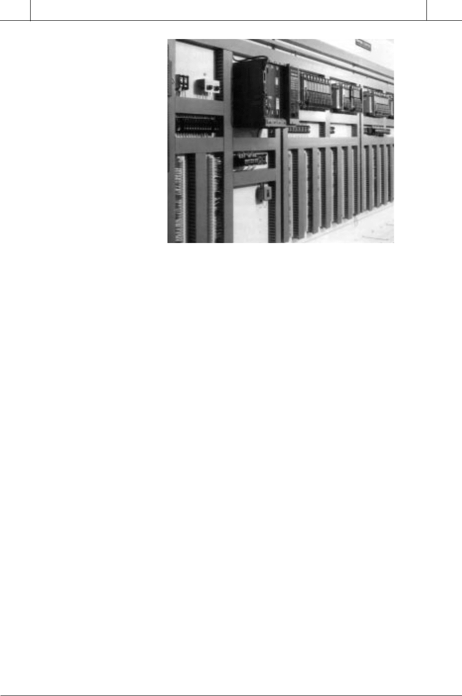
Placement of PLC Components. The placement of the major components
of a specific controller depends on the number of system components and
the physical design or modularity of each component (see Figure 20-3).
927
CHAPTER
20
PLC Start-Up
and Maintenance
SECTION
6
Installation
and Start-Up
Industrial Text & Video Company 1-800-752-8398
www.industrialtext.com
Figure 20-3. Placement of PLC components.
Although different controllers have different mounting and spacing require-
ments, the following considerations and precautions apply when placing any
PLC inside an enclosure:
• To allow maximum convection cooling, all controller components
should be mounted in a vertical (upright) position. Some manufactur-
ers may specify that the controller components can be mounted
horizontally. However, in most cases, components mounted horizon-
tally will obstruct air flow.
• The power supply (main or auxiliary) has a higher heat dissipation
than any other system component; therefore, it should not be mounted
directly underneath any other equipment. The power supply should be
installed at the top of the enclosure above all other equipment, with
adequate spacing (at least ten inches) between the power supply and
the top of the enclosure. The power supply may also be placed
adjacent to other components, but with sufficient spacing.
• The CPU should be located at a comfortable working level (e.g., at
sitting or standing eye level) that is either adjacent to or below the
power supply. If the CPU and power supply are contained in a single
PLC unit, then the PLC unit should be placed toward the top of the
enclosure with no other components directly above it, unless there is
sufficient space.
• Local I/O racks (in the same panel enclosure as the CPU) can be
arranged as desired within the distance allowed by the I/O rack
interconnection cable. Typically, the racks are located below or
adjacent to the CPU, but not directly above the CPU or power supply.
Courtesy of Allen-Bradley, Highland Heights, OH

928
SECTION
6
Installation
and Start-Up
Industrial Text & Video Company 1-800-752-8398
www.industrialtext.com
CHAPTER
20
PLC Start-Up
and Maintenance
• Remote I/O racks and their auxiliary power supplies are generally
placed inside an enclosure at the remote location, following the same
placement practices as described for local racks.
• Spacing of the controller components (to allow proper heat dissipa-
tion) should adhere to the manufacturer’s specifications for vertical
and horizontal spacing between major components.
Placement of Other Components. In general, other equipment inside the
enclosure should be located away from the controller components, to mini-
mize the effects of noise and heat generated by these devices. The following
list outlines some common practices for locating other equipment inside the
enclosure:
• Incoming line devices, such as isolation and constant voltage trans-
formers, local power disconnects, and surge suppressors, should be
located near the top of the enclosure and beside the power supply. This
placement assumes that the incoming power enters at the top of the
panel. The proper placement of incoming line devices keeps power
wire runs as short as possible, minimizing the transmission of electri-
cal noise to the controller components.
• Magnetic starters, contactors, relays, and other electromechanical
components should be mounted near the top of the enclosure in an area
segregated from the controller components. A good practice is to
place a six-inch barrier between the magnetic area and the controller
area. Typically, magnetic components are adjacent and opposite to
the power supply and incoming line devices.
• If fans or blowers are used to cool the components inside the
enclosure, they should be located close to the heat-generating devices
(generally power supply heat sinks). When using fans, outside air
should not be brought inside the enclosure unless a fabric or other
reliable filter is used. Filtration prevents conductive particles and
other harmful contaminants from entering the enclosure.
Grouping Common I/O Modules. The grouping of I/O modules allows
signal and power lines to be routed properly through the ducts, thus minimiz-
ing crosstalk interference. Following are recommendations concerning the
grouping of I/O modules:
• I/O modules should be segregated into groups, such as AC input
modules, AC output modules, DC input modules, DC output mod-
ules, analog input modules, and analog output modules, whenever
possible.
• If possible, a separate I/O rack should be reserved for common input
or output modules. If this is not possible, then the modules should be
