Bryan L. Programmable controllers. Theory and implementation
Подождите немного. Документ загружается.

899
CHAPTER
19
I/O Bus
Networks
SECTION
5
Advanced PLC
Topics and Networks
Industrial Text & Video Company 1-800-752-8398
www.industrialtext.com
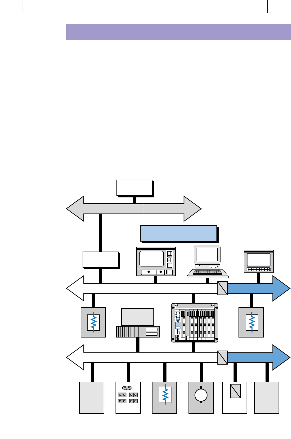
19-5 PROCESS BUS NETWORKS
A process bus network is a high-level, open, digital communication network
used to connect analog field devices to a control system. As mentioned earlier,
a process bus network is used in process applications, where the analog input/
output sensors and actuators respond slower than those in discrete bus
applications (device bus networks). The size of the information packets
delivered to and from these analog field devices is large, due to the nature of
the information being collected at the process level.
The two most commonly used process bus network protocols are Fieldbus and
Profibus (see Section 19-2). Although these network protocols can transmit
data at a speed of 1 to 2 megabits/sec, their response time is considered slow
to medium because of the large amount of information that is transferred.
Nevertheless, this speed is adequate for process applications, because analog
processes do not respond instantaneously, as discrete controls do. Figure 19-
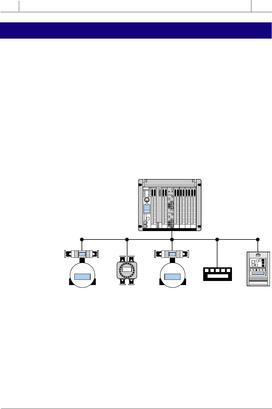
21 illustrates a typical process bus configuration.
Figure 19-21. Process bus configuration.
Process bus networks can transmit enormous amounts of information to a
PLC system, thus greatly enhancing the operation of a plant or process. For
example, a smart, process bus–compatible motor starter can provide informa-
tion about the amount of current being pulled by the motor, so that, if current
requirements increase or a locked-rotor current situation occurs, the system
can alert the operator and avoid a potential motor failure in a critical
production line. Implementation of this type of system without a process bus
network would be too costly and cumbersome because of the amount of wire
runs necessary to transmit this type of process data.
Control
Valve
Control
Valve
Flow
Meter
Pressure
Meter
Intelligent
AC Drive
PLC
900
SECTION
5
Advanced PLC
Topics and Networks
Industrial Text & Video Company 1-800-752-8398
www.industrialtext.com
CHAPTER
19
I/O Bus
Networks
Process bus networks will eventually replace the commonly used analog
networks, which are based on the 4–20 mA standard for analog devices. This
will provide greater accuracy and repeatability in process applications, as
well as add bidirectional communication between the field devices and the
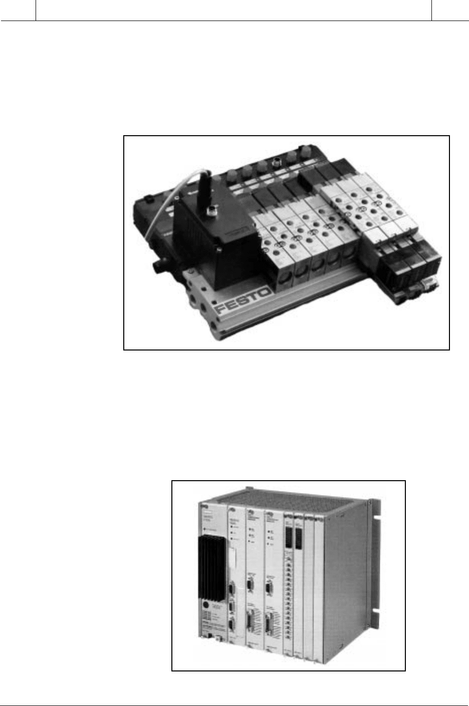
controller (e.g., PLC). Figure 19-22 illustrates an intelligent valve/manifold
system that can be used in a process bus network.
Figure 19-22. Intelligent valve/manifold system compatible with the Fieldbus protocol.
A PLC or computer communicates with a process bus network through a host
controller interface module using either Fieldbus or Profibus protocol format.
Block transfer instructions relay information between the PLC and the
process bus processor. The process bus processor is generally inserted inside
the rack enclosure of the PLC. Figure 19-23 shows a PLC with a Profibus
processor communication interface.
Figure 19-23. Siemens’ Simatic 505 PLC with an integrated Profibus-DP interface.
Courtesy of FESTO Corp., Hauppauge, NY
Courtesy of Siemens, Alpharetta, GA
901
CHAPTER
19
I/O Bus
Networks
SECTION
5
Advanced PLC
Topics and Networks
Industrial Text & Video Company 1-800-752-8398
www.industrialtext.com
FIELDBUS PROCESS BUS NETWORK
The Fieldbus process bus network from the Fieldbus Foundation (FF) is a
digital, serial, multiport, two-way communication system that connects field
equipment, such as intelligent sensors and actuators, with controllers, such as
PLCs. This process bus network offers the desirable features inherent in 4–
20 mA analog systems, such as:
• a standard physical wiring interface
• bus-powered devices on a single pair of wires
• intrinsic safety options
However, the Fieldbus network technology offers the following additional
advantages:
• reduced wiring due to multidrop devices
• compatibility among Fieldbus equipment
• reduced control room space requirements
• digital communication reliability
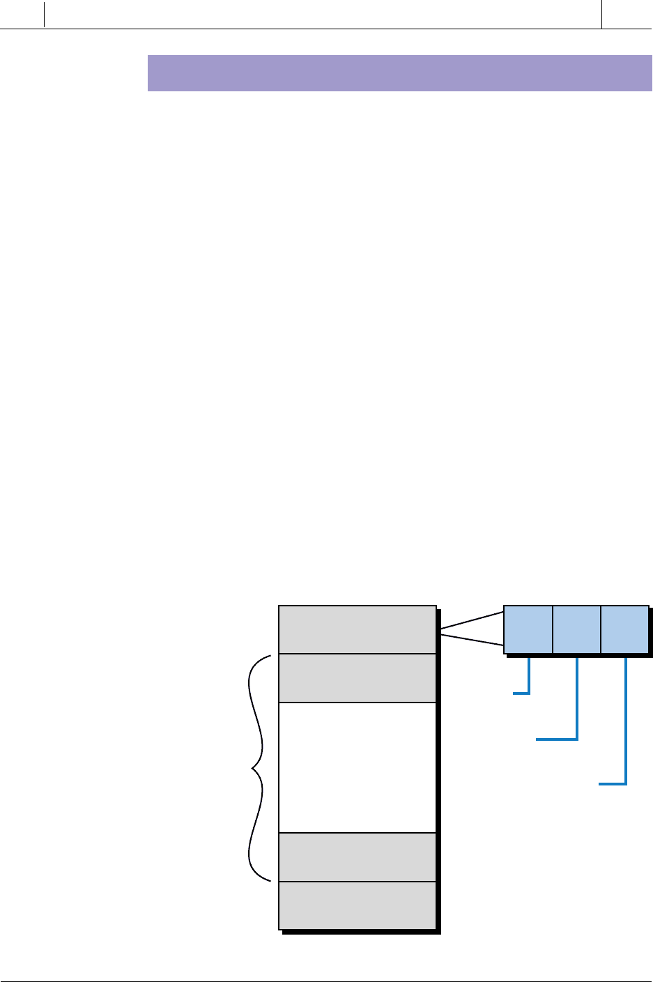
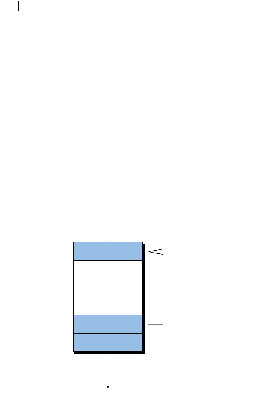
Fieldbus Protocol. The Fieldbus network protocol is based on three layers
of the ISO’s seven-layer model (see Figure 19-24). These three layers are
layer 1 (physical interface), layer 2 (data link), and layer 7 (application). The
section comprising layers 2 and 7 of the model are referred to as the Fieldbus
communication stack. In addition to the ISO’s model, Fieldbus adds an extra
Figure 19-24. Fieldbus protocol.
User Layer
Layer 8
Application Layer
Layer 7
Layers 3 through 6
Not Used
Data Link Layer
Layer 2
Physical Layer
Layer 1
Communications
Stack
FB DDS SM
Function
Blocks
Device
Description
Services
System Management
902
SECTION
5
Advanced PLC
Topics and Networks
Industrial Text & Video Company 1-800-752-8398
www.industrialtext.com
CHAPTER
19
I/O Bus
Networks
layer on top of the application layer called the user layer. This user layer
provides several key functions, which are function blocks, device description
services, and system management.
Physical Layer (Layer 1). The physical layer of the Fieldbus process bus
network conforms with the ISA SP50 and IEC 1152-2 standards. These
standards specify the type of wire that can be used in this type of network, as
well as how fast data can move through the network. Moreover, these
standards define the number of field devices that can be on the bus at different
network speeds, with or without being powered from the bus with intrinsic
safety (IS). Intrinsically safe equipment and wiring does not emit enough
thermal or electrical energy to ignite materials in the surrounding atmosphere.
Thus, intrinsically safe devices are suitable for use in hazardous environments
(e.g., those containing hydrogen or acetylene).
Table 19-3 lists the specifications for the Fieldbus network’s physical layer,
including the type of wire (bus), speed, number of devices, and wiring
characteristics. The Fieldbus has two speeds—a low speed of 31.25 kbaud,
referred to as H1, and a high speed of 1 Mbaud or 2.5 Mbaud (depending on
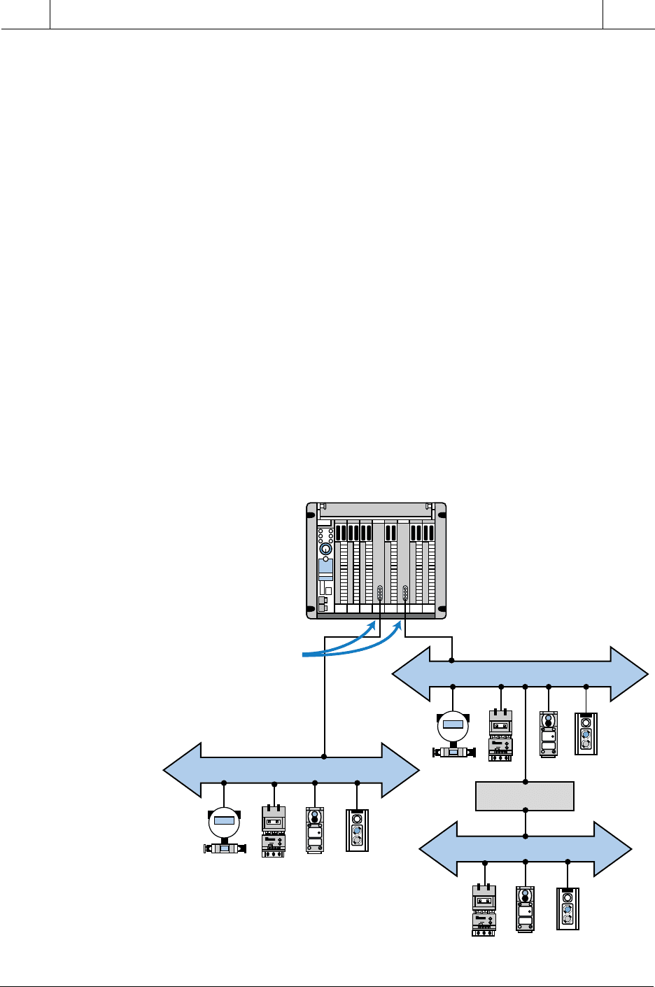
the mode—AC current or DC voltage mode), called H2. Figure 19-25
illustrates how a bridge can connect an H1 Fieldbus network to an H2
Fieldbus network.
Figure 19-25. Bridge connecting low-speed and high-speed Fieldbus networks.
Low-Speed Fieldbus (H1)
PLC
High-Speed Fieldbus (H2)
Low-Speed Fieldbus (H1)
Bridge
Fieldbus
Interfaces

903
CHAPTER
19
I/O Bus
Networks
SECTION
5
Advanced PLC
Topics and Networks
Industrial Text & Video Company 1-800-752-8398
www.industrialtext.com
Table 19-3. Fieldbus physical layer specifications.
eriWfoepyT
epyTsuBdeepS
/seciveDforebmuN
tnemgeSsubdleiF
tnemgeSsuBweN
)riaP-detsiwT/dedleihS(
tnemgeSsuBgnitsixE
)riaPdetsiwtitluM/dedleihS(
)1H(subdeeps-woLduabk52.13subtoneratahtsecived23–2
derewop
suberatahtsecived21–2
derewop
suberatahtsecived6–2
efasyllacisnirtninaniderewop
aera)SI(
*m0091otpu,GWA81#m0021otpu,GWA22#
)2H(subdeeps-hgiHduabM1edomtnerrucCA,secived721
derewop,)ycneuqerfzHK61(
aeraSInisubmorf
m057otpu,GWA22#
duabM1,edomegatlovCD,secived721
ondna,submorfderewopton
secivedSI
m057otpu,GWA22#
duabM5.2,edomegatlovCD,secived721
ondna,submorfderewopton
secivedSI
m005otpu,GWA22#
gnisudetnemelpmieboslanac)1H(subdeeps-wolsubdleiFA*
ehT.m004otputaGWA62#htiwderiwdetsiwtitlum,dedleihsnu
61#htiweriwerocitlum,dedleihsnuesuoslanacsubdeeps-wol
.m002otputaGWA

904
SECTION
5
Advanced PLC
Topics and Networks
Industrial Text & Video Company 1-800-752-8398
www.industrialtext.com
CHAPTER
19
I/O Bus
Networks
At a speed of 31.25 kbaud, the physical layer of the Fieldbus process network
can support existing 4–20 mA wiring. This increases cost-effectiveness when
upgrading a plant or process’s network communication scheme. At this H1
speed, the Fieldbus network can also support intrinsically safe network
segments with bus-powered devices.
Communication Stack (Layers 2 and 7). The communication stack portion
of the Fieldbus process bus network consists of layer 2 (the data link layer)
and layer 7 (the application layer). The data link layer controls the transmis-
sion of messages onto the Fieldbus through the physical layer. It manages
access to the bus through a link active scheduler, which is a deterministic,
centralized bus transmission regulator based on IEC and ISA standards. The
application layer contains the Fieldbus messaging specification (FMS) stan-
dard, which encodes and decodes commands from the user layer, Fieldbus’s
additional 8th layer. The FMS is based on the Profibus process bus standard.
Layer 7 also contains an object dictionary, which allows Fieldbus network
data to be retrieved by either tag name or index record.
The Fieldbus process network uses two types of message transmissions:
cyclic (scheduled) and acyclic (unscheduled). Cyclic message transmissions
occur at regular, scheduled times. The master network device monitors how
busy the network is and then grants the slave devices permission to send
network transmissions at specified times. Other network devices can listen
to and receive these messages if they are subscribers.
Acyclic, or unscheduled, messages occur between cyclic, scheduled mes-
sages, when the master device sends an unscheduled informational message
to a slave device. Typically, acyclic messages involve alarm acknowledg-
ment signals or special retrieving commands designed to obtain diagnostic
information from the field devices.
User Layer (Layer 8). The user layer implements the Fieldbus network’s
distributed control strategy. It contains three key elements, which are function
blocks, device description services, and system management. The user layer,
a vital segment of the Fieldbus network, also defines the software model for
user interaction with the network system.
Function Blocks. Function blocks are encapsulated control functions that
allow the performance of input/output operations, such as analog inputs,
analog outputs, PID control, discrete inputs/outputs, signal selectors, manual
loaders, bias/gain stations, and ratio stations. The function block capabilities
of Fieldbus networks allow Fieldbus-compatible devices to be programmed
with blocks containing any of the instructions available in the system.
Through these function blocks, users can configure control algorithms and
implement them directly through field devices. This gives these intelligent
field devices the capability to store and execute software routines right at
905
CHAPTER
19
I/O Bus
Networks
SECTION
5
Advanced PLC
Topics and Networks
Industrial Text & Video Company 1-800-752-8398
www.industrialtext.com
their connection to the bus. The process information gathered through these
function block programs can then be passed to the host through the network,
either cyclically or acyclically.
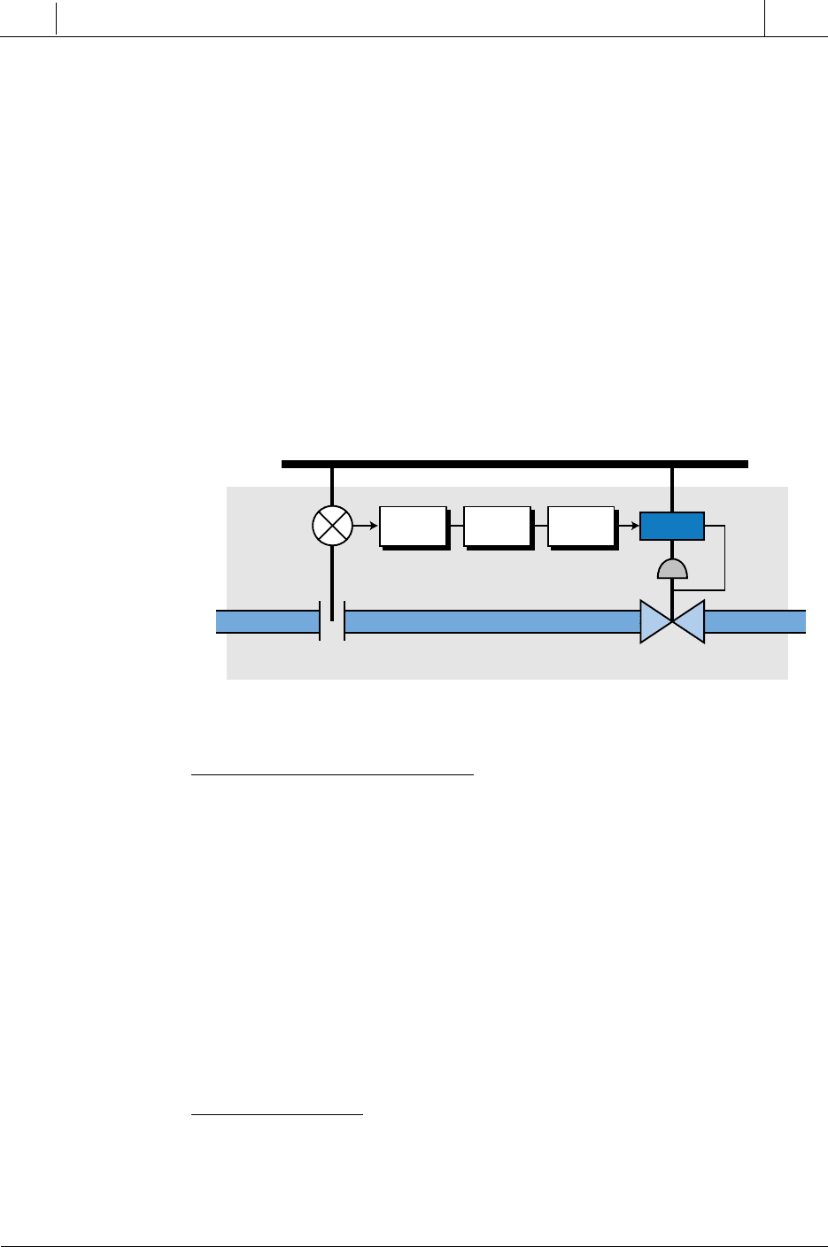
Figure 19-26 illustrates an example of a process control loop that is executed
directly on the Fieldbus network. In this loop, the analog input function block
reads analog process information from the meter/transmitter, executes a PID
function block, and then outputs analog control data to an intelligent process
valve. This configuration creates an independent, self-regulating loop, which
obtains its own analog input data from the flow meter. Information about the
required flow parameters is passed from the host controller to the intelligent
valve system, so that it can properly execute its function blocks. The function
blocks allow the field device to be represented in the network as a collection
of software block instructions, rather than just as an instrument.
Figure 19-26. Process control loop executed on the Fieldbus network.
Device Description Services. Device descriptions (DD) are Fieldbus
software mechanisms that let a host obtain message information, such as
vendor name, available function blocks, and diagnostic capabilities, from
field devices. Device descriptions can be thought of as “drivers” for field
devices connected to the network, meaning that they allow the device to
communicate with the host and the network. The network’s host computer
uses a device description services, or DDS, interpreter to read the desired
information from each device. All devices connected to a Fieldbus process
network must have a device description. When a new field device is added to
the network, the host must be supplied with its device description. Device
descriptions eliminate the need to revise the whole control system software
when revisions are made to existing field device software or when new
devices are added to the process control system.
System Manager. The system management portion of the user layer
schedules the execution of function blocks at precisely defined intervals. It
also controls the communication of all the Fieldbus network parameters used
by the function blocks. Moreover, the system manager automatically assigns
field device addresses.
Valve
Control
Fieldbus Network
Process
Meter/
Transmitter
Analog
Input
PID
Analog
Output
906
SECTION
5
Advanced PLC
Topics and Networks
Industrial Text & Video Company 1-800-752-8398
www.industrialtext.com
CHAPTER
19
I/O Bus
Networks
PROFIBUS PROCESS BUS NETWORK
Profibus is a digital process bus network capable of communicating in-
formation between a master controller (or host) and an intelligent, slave
process field device, as well as from one host to another. Profibus actually
consists of three intercompatible networks with different protocols designed
to serve distinctive application requirements. The three types of Profibus
networks are:
• Profibus-FMS
• Profibus-DP
• Profibus-PA
The Profibus-FMS network is the universal solution for communicating
between the upper level, the cell level, and the field device level of the
Profibus hierarchy (see Figure 19-27). Cell level control occurs at individual
Figure 19-27. Profibus hierarchy.
Profibus-FMS
Information Network TCP/IP
Profibus-PA
Profibus-DP Profibus-FMS Profibus-PA
PLC
Host
Computer
Gateway
Profibus
Application Range
Sensor Sensor
Sensor
Trans-
mitter
Field
Device
Field
Device
I/O
Drive
M
PCS
CNC
Node
Controller
Upper
Level
Cell
Level
Field
Level
907
CHAPTER
19
I/O Bus
Networks
SECTION
5
Advanced PLC
Topics and Networks
Industrial Text & Video Company 1-800-752-8398
www.industrialtext.com
(or cell) areas, which exercise the actual control during production. The
controllers at the cell level must communicate with other supervisory sys-
tems. The Profibus-FMS utilizes the Fieldbus message specification (FMS)
to execute its extensive communication tasks between hierarchical levels.
This communication is performed through cyclic or acyclic messages at
medium transmission speeds.
The Profibus-DP network is a performance-optimized version of the Profibus
network. It is designed to handle time-critical communications between
devices in factory automation systems. The Profibus-DP is a suitable replace-
ment for 24-V parallel and 4–20 mA wiring interfaces.
The Profibus-PA network is the process automation version of the Profibus
network. It provides bus-powered stations and intrinsic safety according to
the transmission specifications of the IEC 1158-2 standard. The Profibus-PA
network has device description and function block capabilities, along with
field device interoperability.
Profibus Network Protocol. The Profibus network follows the ISO model;
however, each type of Profibus network contains slight variations in the
model’s layers. The Profibus-FMS does not define layers 3 through 6; rather,
it implements their functions in a lower layer interface (LLI) that forms part
of layer 7 (see Figure 19-28). The Profibus-FMS implements the Fieldbus
message specification (FMS), which provides powerful network communi-
cation services and user interfaces, in layer 7 as well.
Figure 19-28. Profibus-FMS protocol.
Application Layer
Layer 7
Layers 3–6
not used
Data Link Layer
(Layer 2)
Physical Layer
(Layer 1)
User
Profibus-FMS
Network
• Fieldbus Message Specification (FMS)
• Lower Layer Interface (LLI)
• Fieldbus Data Link (FDL)
908
SECTION
5
Advanced PLC
Topics and Networks
Industrial Text & Video Company 1-800-752-8398
www.industrialtext.com
CHAPTER
19
I/O Bus
Networks
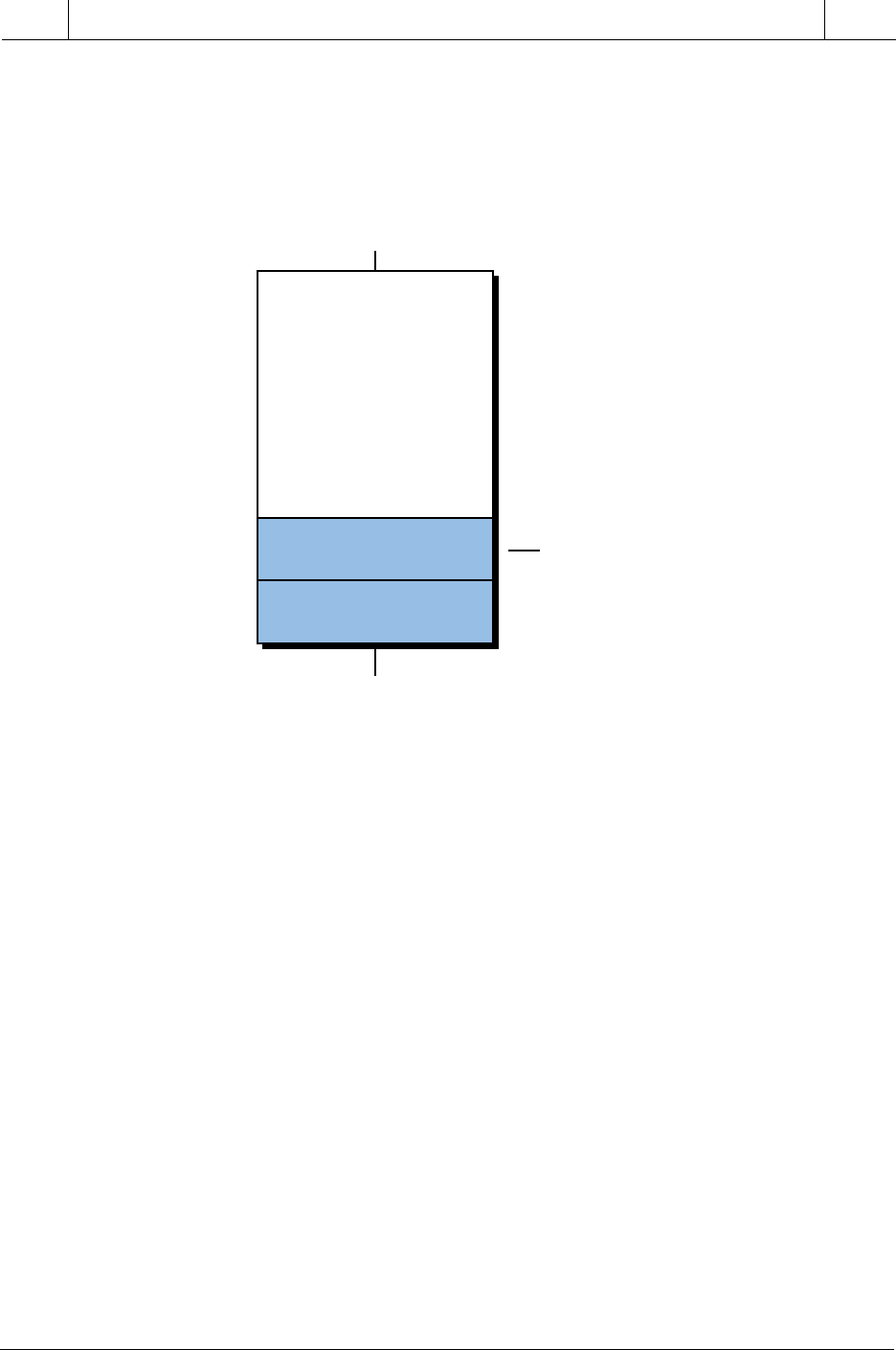
The Profibus-DP network, on the other hand, does not define layers 3 through
7 (see Figure 19-29). It omits layer 7 primarily to achieve the high operational
speed required for its applications. A direct data link mapper (DDLM),
located in layer 2, provides the mapping between the user interface and layer
2 of the Profibus-DP network.
Figure 19-29. Profibus-DP protocol.
The Profibus-PA network uses the same type of model as the Profibus-FMS
(see Figure 19-30), except its seventh layer differs slightly. Layer 7 imple-
ments the function block control software and also contains a device descrip-
tion language used for field device identification and addressing.
The data link layer, designated in the Profibus network as the fieldbus data
link layer (FDL), executes all message and protocol transmissions. This data
layer is equivalent to layer 2 of the ISO model. The fieldbus data link layer
also provides medium access control (MAC) and data integrity. Medium
access control ensures that only one station has the right to transmit data at any
time. Because Profibus can communicate between masters with equal access
rights (e.g., two PLCs), medium access control is used to provide each of the
master stations with the opportunity to execute their communication tasks
within precisely defined time intervals. For communication between a master
and slave field devices, cyclic, real-time data exchange is achieved as quickly
as possible through the network.
The Profibus’s medium access protocol is a hybrid communication method
that includes a token-passing protocol for use between masters and a master-
slave protocol for communication between a master and a field device.
Layers 3–7
not used
Data Link Layer
(Layer 2)
Physical Layer
(Layer 1)
User
Profibus-FMS
Network
• Direct Data Link Mapper (DDLM)
