Bryan L. Programmable controllers. Theory and implementation
Подождите немного. Документ загружается.

909
CHAPTER
19
I/O Bus
Networks
SECTION
5
Advanced PLC
Topics and Networks
Industrial Text & Video Company 1-800-752-8398
www.industrialtext.com
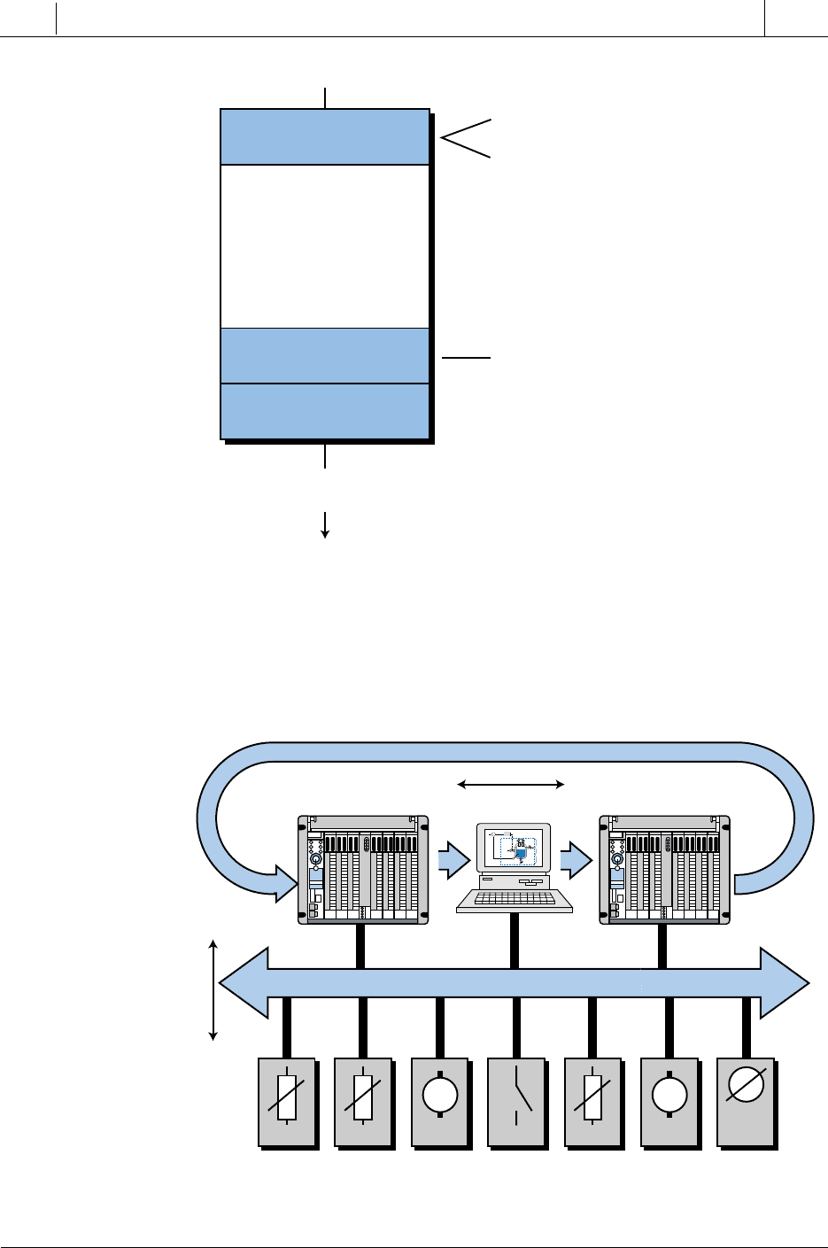
Through this hybrid medium access protocol, a Profibus network can function
as a master-slave system, a master-master system (token passing), or a
combination of both systems (see Figure 19-31).
Figure 19-30. Profibus-PA protocol.
Figure 19-31. Master-slave and master-master Profibus communications.
Actuator
Trans-
mitter
V
Drive
M
Sensor Sensor Drive
M
Sensor
Profibus
Passive Stations, Slave Devices
PLC
PLC
Master
Slave
Master Master
Hc
E = SP – PV CV
PV
SP
+
–
Σ
Steam
Batch
Temperature
Sensor
Steam
Return
Hp
Application Layer
(Layer 7)
Layers 3–6
not used
Data Link Layer
(Layer 2)
Physical Layer
(Layer 1)
User
Network
Profibus-PA
• Function Block (FB)
• Device Description Language (DDL)
• Fieldbus Message Specification (FMS)
• Lower Layer Interface (LLI)
• Fieldbus Data Link (FDL)
910
SECTION
5
Advanced PLC
Topics and Networks
Industrial Text & Video Company 1-800-752-8398
www.industrialtext.com
CHAPTER
19
I/O Bus
Networks
As mentioned earlier, layer 2 of the Profibus network is responsible for data
integrity, which is ensured through the Hamming Distance HD = 4 error
detection method. The Hamming distance method can detect errors in the
transmission medium, as well as in the transceivers. As defined by the IEC
870-5-1 standard, this error detection method uses special start and end
delimiters, along with slip-free synchronization and a parity bit for 8 bits.
Profibus networks support both peer-to-peer and multipeer communication in
either broadcast or multicast configurations. In broadcast communication, an
active station sends an unconfirmed message to all other stations. Any of these
stations (including both masters and slaves) can take this information. In
multicast communication, an active station sends an unconfirmed message to
a particular group of master or slave stations.
The physical layer, or layer 1, of the ISO model defines the network’s
transmission medium and the physical bus interface. The Profibus network
adheres to the EIA RS-485 standard, which uses a two-conductor, twisted-
pair wire bus with optional shielding. The bus must have proper terminations
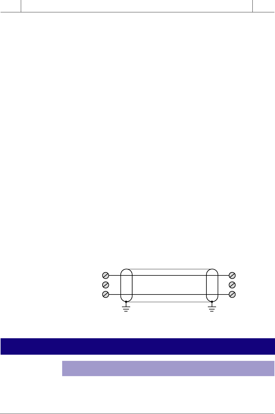
at both ends. Figure 19-32 illustrates the pin assignment used in the Profibus.
The maximum number of stations or device nodes per segment is 32 without
repeaters and 127 with repeaters. The network transmission speed is select-
able from 9.6 kbaud to 12 Mbaud, depending on the distance and cable type.
Without repeaters, the maximum bus length is 100 m at 12 Mbaud. With
conventional type-A copper bus cable, the maximum distance is 200 m at 1.5
Mbaud. This distance can be increased to up to 1.2 km if the speed of the
network is reduced to 93.75 kbaud. With type-B cable, the maximum distance
is 200 m at 500 kbaud and up to 1.2 km at 93.75 kbaud. The type of connector
used is a 9-pin, D-sub connector.
19-6 I/O BUS INSTALLATION AND WIRING CONNECTIONS
INSTALLATION GUIDELINES
One of the most important aspects of an I/O bus network installation is the use
of the correct type of cable, number of conductors, and type of connectors for
the network being used. In device bus networks, the number of conductors and
Figure 19-32. Profibus pin assignment.
Station #1 Station #2
RxD/TxD+ 3
DGND 5
RxD/TxD– 8
Pin #
3 RxD/TxD+
5 DGND
8 RxD/TxD–
Pin #
Shield
Protective Ground
911
CHAPTER
19
I/O Bus
Networks
SECTION
5
Advanced PLC
Topics and Networks
Industrial Text & Video Company 1-800-752-8398
www.industrialtext.com
type of communication standard (i.e., RS-485, RS-422, etc.) varies depend-
ing on the specific network (e.g., DeviceNet, Seriplex, ASI, Profibus,
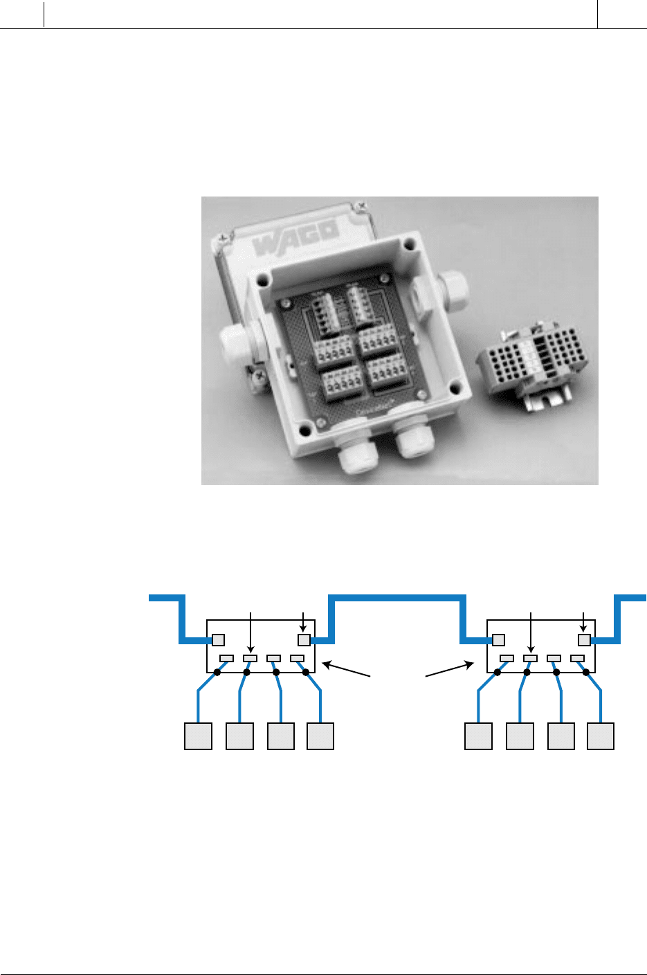
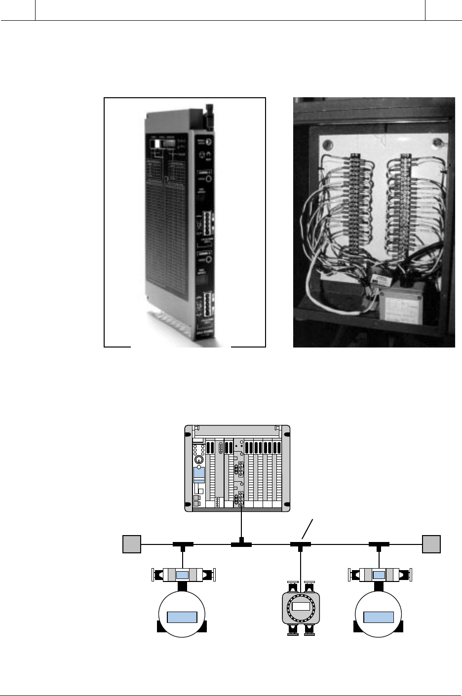
Fieldbus, etc.). The connector ports (see Figure 19-33), which connect the I/O
field devices to the I/O bus network, can be implemented in either an open or
an enclosed configuration. Figure 19-34 illustrates the port connections for a
DeviceNet I/O bus network.
Figure 19-33. Connector ports from a DeviceNet bus network (left: enclosed, right: open).
Figure 19-34. DeviceNet I/O bus port connections.
In general, an enclosed configuration can connect from 4 to 8 I/O field
devices in one drop, while an open configuration can accommodate two to
four I/O devices. Enclosed connector ports are used when the network must
be protected from the environment, as in a NEMA 4–type enclosure. Open
ports are used when replacing I/O connections in a system that already has a
DIN rail installation, where the open ports can be easily mounted onto the rail.
Courtesy of WAGO, Brown Deer, WI
I/O Devices
DeviceNet Network
(Multiwire Cable)
Ports
taps trunk
I/O Devices
taps trunk
912
SECTION
5
Advanced PLC
Topics and Networks
Industrial Text & Video Company 1-800-752-8398
www.industrialtext.com
CHAPTER
19
I/O Bus
Networks
DEVICE BUS NETWORK WIRING GUIDELINES
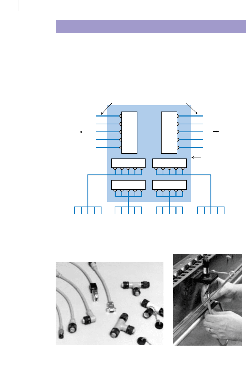
Figure 19-35. CANbus DeviceNet wiring diagram for the multiport tap in Figure 19-34.
Figure 19-36. (a) Plug-and-play connectors and (b) their installation.
Figure 19-35 illustrates a typical wiring diagram connection for a DeviceNet
CANbus network. Note that the two trunk connections constitute the main
cable of the network, with the five wires providing signal, power, and
shielding. A printed circuit board assembly internally connects the two trunk
connectors, or ports, and the I/O device taps. Most manufacturers of device
bus networks provide “plug-and-play” connectors and wiring systems, which
facilitate installation and system modifications (see Figure 19-36).
Courtesy of Honeywell’s MicroSwitch Division, Freeport, IL
Courtesy of Honeywell’s MicroSwitch Division, Freeport, IL
(a)
(b)
V–
L
SH
H
V+
V–
L
SH
H
V+
Trunk 1 Trunk 2
Tap 1
Tap 4
Tap 2 Tap 3
V- L SH H V+
V- L SH H V+ V- L SH H V+V- L SH H V+
I/O Device
Drop #1
I/O Device
Drop #2
I/O Device
Drop #3
I/O Device
Drop #4
To
Other
Ports
To
Other
Ports
DeviceNet Main Network Trunk Cable
Printed
Circuit Board

913
CHAPTER
19
I/O Bus
Networks
SECTION
5
Advanced PLC
Topics and Networks
Industrial Text & Video Company 1-800-752-8398
www.industrialtext.com
The majority of device bus networks require that a terminator resistor be
present at the end of the main trunk line for proper operation and transmission
of network data. Each network may also specify the number of nodes that can
be connected to the network, the speed of transmission depending on the trunk
length, and the maximum drop length at which field devices can be installed.
The network may also limit the cumulative drop length, meaning that the
combined lengths of all the drops cannot exceed a particular specification.
Table 19-4 shows the specifications for Allen-Bradley’s DeviceNet commu-
nication link network.
Table 19-4. DeviceNet specifications.
PROCESS BUS NETWORK WIRING GUIDELINES
Cable criteria similar to device bus networks apply to process bus networks.
Depending on the network protocol specifications, specifically those of layer
1 (physical) of the OSI model, the conductor may be twisted pair or coaxial,
operating at different network transmission speeds. Table 19-5 shows the
wiring and network speed characteristics of the Fieldbus Foundation network
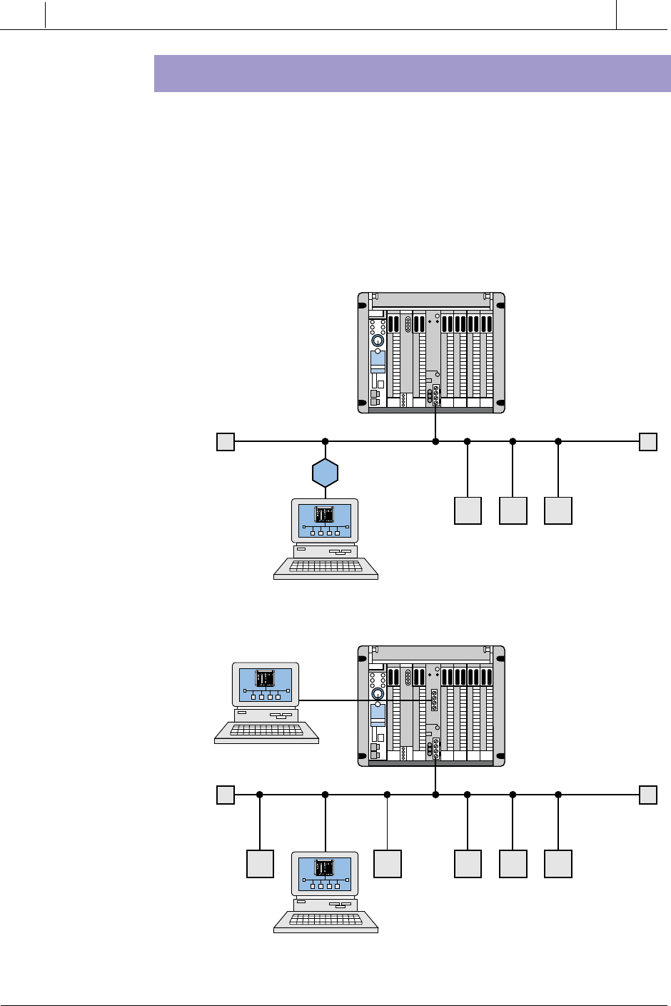
(Fieldbus protocol). Figure 19-37 shows the process bus interface for Allen-
Bradley’s family of PLCs, which is compatible with the Profibus protocol.
This Profibus interface can work at network speeds of 9.6, 19.2, 93.75, 187.5,
Table 19-5. Fieldbus network characteristics.
ataD
noissimsnarT
etaR
knurT
htgneL
porD.xaM
htgneL
fo#.xaM
sedoN
evitalumuC
htgneLporD
ces/stibK521
m005
)tf0461(
m3
)tf01(
46
m651
)tf215(
ces/stibK052
m002
)tf656(
m87
)tf652(
ces/stibK005
m001
)tf823(
m93
)tf821(
etaRataD
wolSdradnatShgiH
deepS spbK52.13spbM1spbM.2
elbaC riap-detsiwtriap-detsiwtriap-detsiwt
ecnatsiDm0091m057m005
914
SECTION
5
Advanced PLC
Topics and Networks
Industrial Text & Video Company 1-800-752-8398
www.industrialtext.com
CHAPTER
19
I/O Bus
Networks
and 500 kbits/sec. Process bus wiring installations may also require a
termination block at the end of the wiring. T-junction connectors provide the
connections to different I/O field devices (see Figure 19-38).
Figure 19-37. (a) Allen-Bradley’s Profibus process bus interface and (b) the wiring installa-
tion of a Fieldbus network using two sets of shielded twisted-pair wire.
Figure 19-38. Fieldbus network using T-junction connectors.
Courtesy of Allen-Bradley, Highland Heights, OH
Fieldbus Interface
Smart
Control Valve
Smart
Control Valve
Smart
Flow Meter
Termination
Block
T-Junction
Connector
Termination
Block
(a)
Courtesy of Fieldbud Foundation, Austin, TX
(b)
915
CHAPTER
19
I/O Bus
Networks
SECTION
5
Advanced PLC
Topics and Networks
Industrial Text & Video Company 1-800-752-8398
www.industrialtext.com
I/O BUS NETWORK ADDRESSING
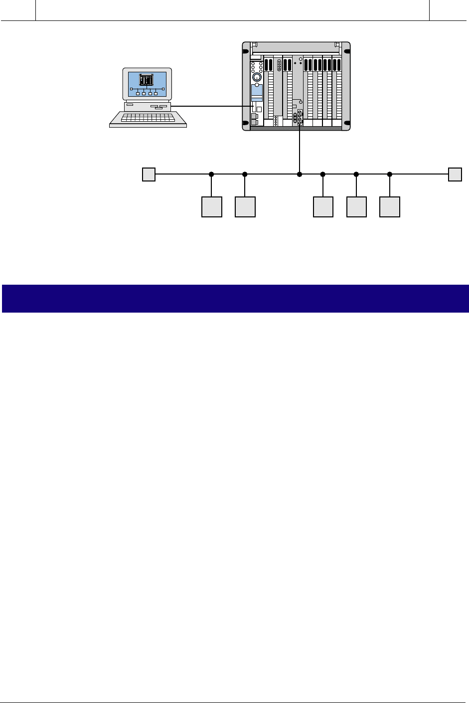
Addressing of the I/O devices in an I/O bus network occurs during the
configuration, or programming, of the devices in the system. Depending on
the PLC, this addressing can be done either directly on the bus network via a
PC and a gateway (see Figure 19-39a) or through a PC connected directly to
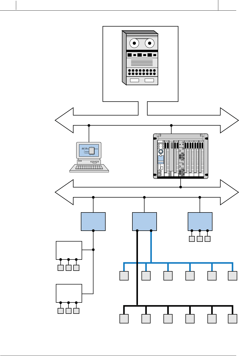
the bus network interface (see Figure 19-39b). It can also be done through the
PLC’s RS-232 port (see Figure 19-40). Some I/O bus networks have switches
that can be used to define device addresses, while others have a predefined
address associated with each node drop.
Figure 19-39. I/O addresses assigned using (a) a PC connected to the network through
a gateway and (b) a PC connected directly to the network.
I/O Bus Network
I/O Field Devices
Terminator Terminator
Gateway
Terminator Terminator
I/O Bus Network
I/O Field Devices
Terminator Terminator
Terminator Terminator
(a)
(b)
Terminator Terminator
916
SECTION
5
Advanced PLC
Topics and Networks
Industrial Text & Video Company 1-800-752-8398
www.industrialtext.com
CHAPTER
19
I/O Bus
Networks
19-7 SUMMARY OF I/O BUS NETWORKS
The device and process types of I/O bus networks provide incredible potential
system cost savings, which are realized during installation of a control
system. These two types of I/O networks can also form part of a larger,
networked operation, as shown in Figure 19-41. In this operation, the
information network communicates via Ethernet between the main computer
system (or a personal computer) and a supervisory PLC. In turn, these PLCs
communicate with other processors through a local area control network. The
PLCs may also have remote I/O, device bus, and process bus subnetworks.
The addition of field devices to this type of I/O network is relatively easy, as
long as each field device is compatible with its respective I/O bus network
protocol.
The main difference between the device bus and the process bus networks is
the amount of data transmitted. This is due to the type of application in which
each is used. Device bus networks are used in discrete applications, which
transmit small amounts of information, while process bus networks are used
in process/analog applications, which transmit large amounts of data. Figure
19-42 shows a graphic representation of these networks based on the potential
amount of information that can be transmitted through them.
In terms of cost, a process bus network tends to be more expensive to
implement than a device bus network, simply because analog I/O field
devices are more expensive. Also, the intelligence built into a process bus
network is more costly than the technology incorporated into a device bus
network. For example, the CAN, SDS, ASI, ASIC, and InterBus-S chips used
in device networks are readily available, standard, off-the-shelf chips, which
Figure 19-40. I/O addresses assigned using a PC connected to the PLC’s RS-232 port.
I/O Bus Network
I/O Field DevicesI/O Field Devices
Terminator Terminator
RS-232
PLC Port
Terminator Terminator
917
CHAPTER
19
I/O Bus
Networks
SECTION
5
Advanced PLC
Topics and Networks
Industrial Text & Video Company 1-800-752-8398
www.industrialtext.com
Figure 19-41. Large plantwide network.
Information Network (TCP/IP)
Plant Computer
System
Local Area Network
Windows
Computer
Supervisory
PLCs
PLC PLC PLC
I/O Devices
Discrete I/O Devices
Process I/O Devices
Remote
I/O
I/O Devices
Remote
I/O
I/O Devices
Device Bus Network
Process Bus Network
Finished
Conditions
to trigger report
Custom Report
Function Block
Temp_Var
Press_Var
Variable_1
Report
Variable_2
Values
passed from
variables

918
SECTION
5
Advanced PLC
Topics and Networks
Industrial Text & Video Company 1-800-752-8398
www.industrialtext.com
CHAPTER
19
I/O Bus
Networks
Figure 19-42. Network data transmission comparison.
can be purchased at a relatively low cost. Process bus networks, on the other
hand, require devices with more sophisticated electronics, such as micropro-
cessors, memory chips, and other supporting electronic circuitry, which
makes process network I/O devices more expensive. This expense, however,
is more than offset by the total savings for system wiring and installation,
especially in the modernization of existing operations where wire runs may
already be in place.
acyclic message
bit-wide bus network
byte-wide bus network
cyclic message
device bus network
I/O bus network
I/O bus network scanner
medium access control (MAC)
process bus network
tree topology
1–4 Bits
8–256 Bytes
up to 1000 Bytes
Many
Bytes
Few
Bytes
Few
Bits
Network Information
Device bus Process Bus
Bit-wide Byte-wide
KEY
TERMS
