Bryan L. Programmable controllers. Theory and implementation
Подождите немного. Документ загружается.


I/O BUS
NETWORKS
CHAPTER
NINETEEN
Necessity is the mother of invention.
—Latin Proverb
Industrial Text & Video Company 1-800-752-8398
www.industrialtext.com

880
SECTION
5
Advanced PLC
Topics and Networks
Industrial Text & Video Company 1-800-752-8398
www.industrialtext.com
CHAPTER
19
I/O Bus
Networks
Advances in large-scale electronic integration and surface-mount technology,
coupled with trends towards decentralized control and distributed intelli-
gence to field devices, have created the need for a more powerful type of
network—the I/O bus network. This new network lets controllers better
communicate with I/O field devices, to take advantage of their growing
intelligence. In this chapter, we will introduce the I/O bus concept and
describe the two types of I/O bus networks—device-level bus and process
bus. In our discussion, we will explain these network’s standards and features.
We will also list the specifications for I/O bus networks and summarize their
uses in control applications. When you finish this chapter, you will have
learned about all the aspects of a PLC control system—hardware, software,
and communication schemes—and you will be ready to apply this knowl-
edge to the installation and maintenance of a PLC system.
19-1 INTRODUCTION TO I/O BUS NETWORKS
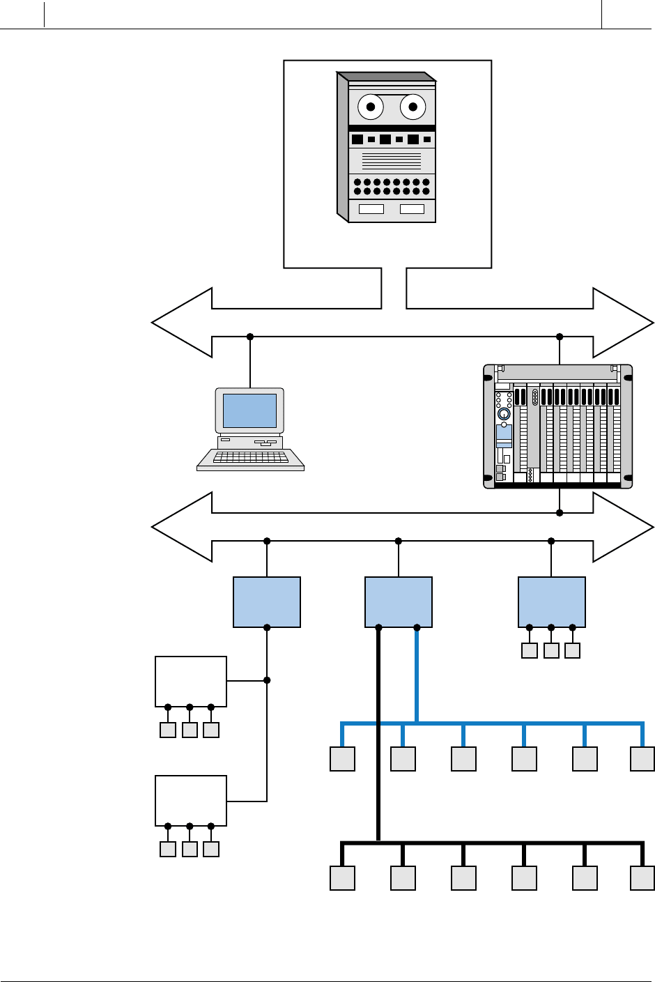
I/O bus networks allow PLCs to communicate with I/O devices in a manner
similar to how local area networks let supervisory PLCs communicate with
individual PLCs (see Figure 19-1). This configuration decentralizes control
in the PLC system, yielding larger and faster control systems. The topology,
or physical architecture, of an I/O bus network follows the bus or extended bus
(tree) configuration, which lets field devices (e.g., limit, photoelectric, and
proximity switches) connect directly to either a PLC or to a local area network
bus. Remember that a bus is simply a collection of lines that transmit data
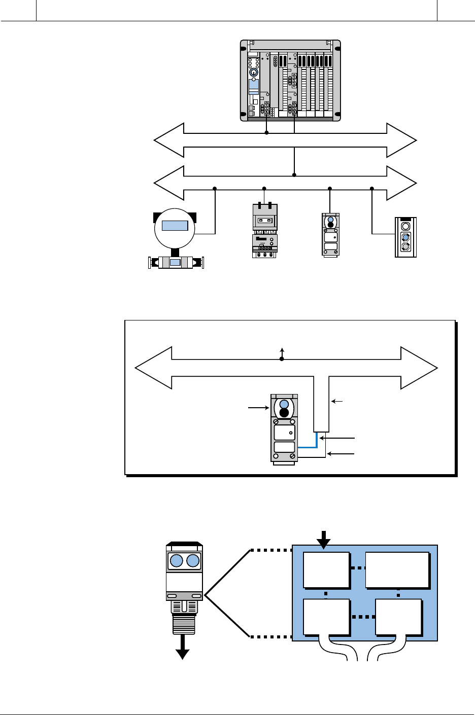
and/or power. Figure 19-2 illustrates a typical connection between a PLC,
a local area network, and an I/O bus network.
The basic function of an I/O bus network is to communicate information
with, as well as supply power to, the field devices that are connected to the
bus (see Figure 19-3). In an I/O bus network, the PLC drives the field devices
directly, without the use of I/O modules; therefore, the PLC connects to and
communicates with each field I/O device according to the bus’s protocol. In
essence, PLCs connect with I/O bus networks in a manner similar to the way
they connect with remote I/O, except that PLCs in an I/O bus use an I/O bus
network scanner. An I/O bus network scanner reads and writes to each
field device address, as well as decodes the information contained in the
network information packet. A large, tree topology bus network (i.e., a
network with many branches) may have up to 2048 or more connected
discrete field devices.
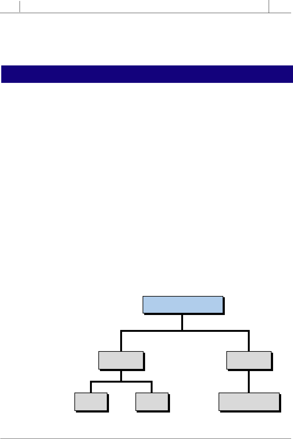
The field devices that connect to I/O bus networks contain intelligence in
the form of microprocessors or other circuits (see Figure 19-4). These devices
communicate not only the ON/OFF state of input and output controls, but
also diagnostic information about their operating states. For example, a
photoelectric sensor (switch) can report when its internal gain starts to
CHAPTER
HIGHLIGHTS
881
CHAPTER
19
I/O Bus
Networks
SECTION
5
Advanced PLC
Topics and Networks
Industrial Text & Video Company 1-800-752-8398
www.industrialtext.com
Figure 19-1. I/O bus network block diagram.
Information Network
Plant Computing
System
Local Area Network
Windows
Computer
Supervisory
PLCs
PLC PLC PLC
I/O Devices
Discrete I/O Devices
Process I/O Devices
Remote
I/O
I/O Devices
Remote
I/O
I/O Devices
Device Bus Network
Process Bus Network
882
SECTION
5
Advanced PLC
Topics and Networks
Industrial Text & Video Company 1-800-752-8398
www.industrialtext.com
CHAPTER
19
I/O Bus
Networks
Figure 19-3. Connections for an I/O bus network.
Figure 19-4. Intelligent field device.
Figure 19-2. Connection between a PLC, a local area network, and an I/O bus network.
Local Area Network
I/O Bus Network
PLC
(Control Network)
Control Valves
Photoelectric
Switches
Motor
Starters
Push Button
Station
Sensor
Circuit
Micro-
controller/
Network Chip
Sensor’s Input
To I/O Bus
Network
To I/O Bus
Network
Network
Receive/
Transmit
Power
In
I/O Bus Network
To PLC Adapter
(I/O Bus Network Scanner)
Connection to
I/O Field Device
Power
Information
Status Signal
Intelligent
Photoelectric
Sensor
883
CHAPTER
19
I/O Bus
Networks
SECTION
5
Advanced PLC
Topics and Networks
Industrial Text & Video Company 1-800-752-8398
www.industrialtext.com
decrease because of a dirty lens, or a limit switch can report the number of
motions it has performed. This type of information can prevent I/O device
malfunction and can indicate when a sensor has reached the end of its
operating life, thus requiring replacement.
19-2 TYPES OF I/O BUS NETWORKS
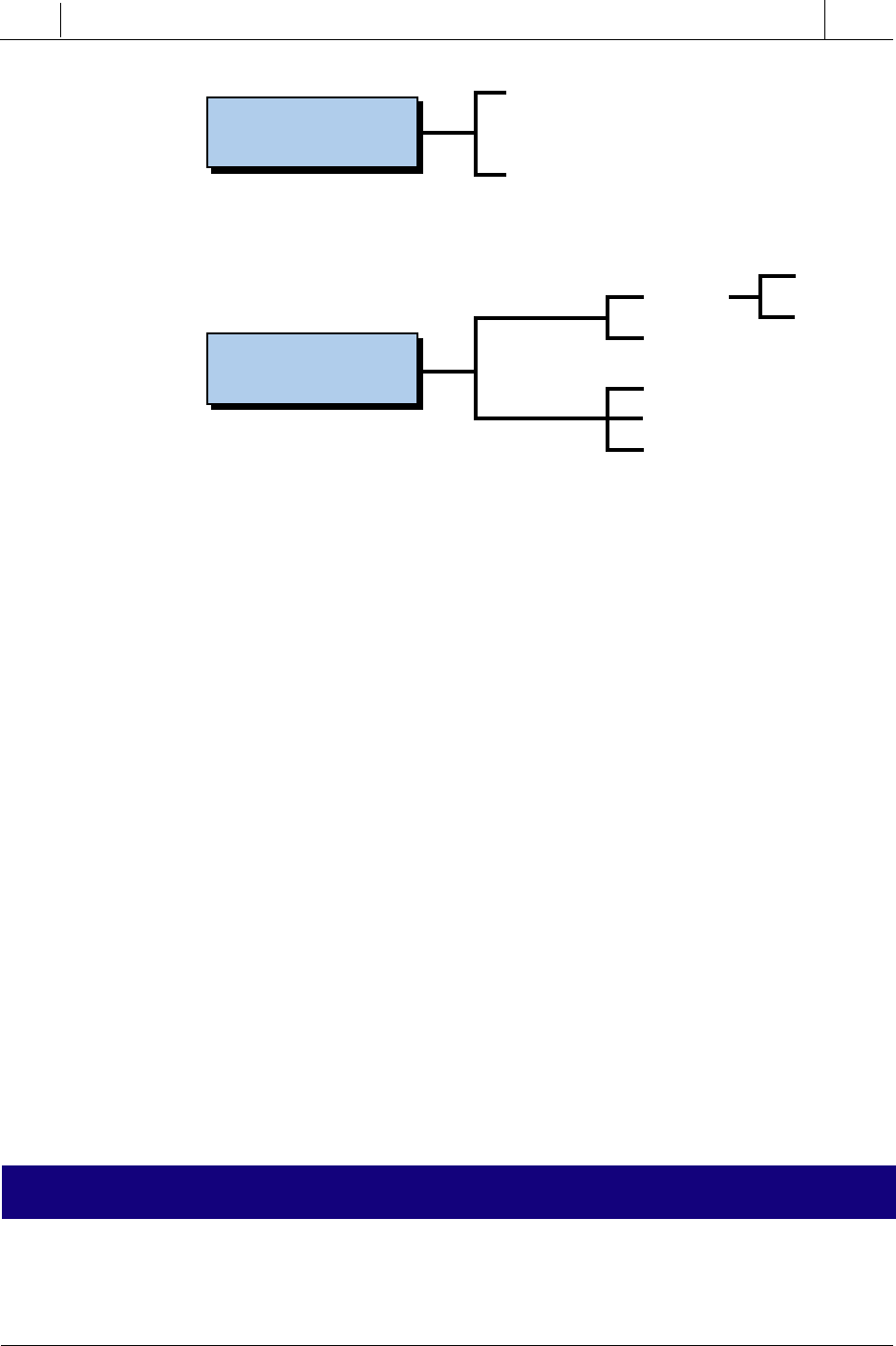
I/O bus networks can be separated into two different categories—one that
deals with low-level devices that are typical of discrete manufacturing
operations and another that handles high-level devices found in process
industries. These bus network categories are:
• device bus networks
• process bus networks
Device bus networks interface with low-level information devices (e.g.,
push buttons, limit switches, etc.), which primarily transmit data relating to
the state of the device (ON/OFF) and its operational status (e.g., operating
OK). These networks generally process only a few bits to several bytes of data
at a time. Process bus networks, on the other hand, connect with high-level
information devices (e.g., smart process valves, flow meters, etc.), which are
typically used in process control applications. Process bus networks handle
large amounts of data (several hundred bytes), consisting of information
about the process, as well as the field devices themselves. Figure 19-5
illustrates a classification diagram of the two types of I/O bus networks.
The majority of devices used in process bus networks are analog, while most
devices used in device bus networks are discrete. However, device bus
networks sometimes include analog devices, such as thermocouples and
variable speed drives, that transmit only a few bytes of information. Device
Figure 19-5. I/O bus network classification diagram.
I/O Bus Network
Discrete
Byte-Wide
Data
Bit-Wide
Data
Several Hundred
Data Bytes
Analog
Device Bus
Network
Process Bus
Network

884
SECTION
5
Advanced PLC
Topics and Networks
Industrial Text & Video Company 1-800-752-8398
www.industrialtext.com
CHAPTER
19
I/O Bus
Networks
bus networks that include discrete devices, as well as small analog devices,
are called byte-wide bus networks. These networks can transfer between 1
and 50 or more bytes of data at a time. Device bus networks that only interface
with discrete devices are called bit-wide bus networks. Bit-wide networks
transfer less than 8 bits of data from simple discrete devices over relatively
short distances.
The primary reason why device bus networks interface mainly with discrete
devices and process bus networks interface mainly with analog devices is the
different data transmission requirements for these devices. The size of the
information packet has an inverse effect on the speed at which data travels
through the network. Therefore, since device bus networks transmit only
small amounts of data at a time, they can meet the high speed requirements
for discrete implementations. Conversely, process bus networks work slower
because of their large data packet size, so they are more applicable for the
control of analog I/O devices, which do not require fast response times. The
transmission speeds for both types of I/O bus networks can be as high as 1 to
2.5 megabits per second. However, a device bus network can deliver many
information packets from many field devices in the time that it takes a process
bus network to deliver one large packet of information from one device.
Since process bus networks can transmit several hundred bytes of data at a
time, they are suitable for applications requiring complex data transmission.
For example, an intelligent, process bus network–compatible pressure trans-
mitter can provide the controller with much more information than just
pressure; it can also transmit information about temperature flow rate and
internal operation. Thus, this type of pressure transmitter requires a large data
packet to transmit all of its process information, which is why a process bus
network would be appropriate for this application. This amount of informa-
tion just would not fit on a device bus network.
PROTOCOL STANDARDS
Neither of the two I/O bus networks have established protocol standards;
however, many organizations are working towards developing both discrete
and process bus network specifications. In the process bus area, two main
organizations, the Fieldbus Foundation (which is the result of a merger
between the Interoperable Systems Project, ISP, Foundation and the World
FIP North American group) and the Profibus (Process Field Bus) Trade
Organization, are working to establish network and protocol standards. Other
organizations, such as the Instrument Society of America (ISA) and the
European International Electronics Committee (IEC), are also involved in
developing these standards. This is the reason why some manufacturers
specify that their analog products are compatible with Profibus, Fieldbus, or
another type of protocol communication scheme. Figure 19-6 illustrates a
block diagram of available network and protocol standards.
885
CHAPTER
19
I/O Bus
Networks
SECTION
5
Advanced PLC
Topics and Networks
Industrial Text & Video Company 1-800-752-8398
www.industrialtext.com
Although no proclaimed standards exist for device bus network applications,
several de facto standards are emerging due to the availability of company-
specific protocol specifications from device bus network manufacturers.
These network manufacturers or associations provide I/O field device manu-
facturers with specifications in order to develop an open network architecture,
(i.e., a network that can interface with many types of field devices). In this
way, each manufacturer hopes to make its protocol the industry standard. One
of these de facto standards for the byte-wide device bus network is DeviceNet,
originally from PLC manufacturer Allen-Bradley and now provided by an
independent spin-off association called the Open DeviceNet Vendor Asso-
ciation. Another is SDS (Smart Distributed System) from Honeywell. Both
of these device bus protocol standards are based on the control area network
bus (CANbus), developed for the automobile industry, which uses the
commercially available CAN chip in its protocol. InterBus-S from Phoenix
Contact is another emerging de facto standard for byte-wide device bus
network.
The de facto standards for low-end, bit-wide device bus networks include
Seriplex, developed by Square D, and ASI (Actuator Sensor Interface), a
standard developed by a consortium of European companies. Again, this is
why I/O bus network and field device manufacturers will specify compatibil-
ity with a particular protocol (e.g., ASI, Seriplex, InterBus-S, SDS, or
DeviceNet) even though no official protocol standard exists.
Figure 19-6. Network and protocol standards.
19-3 ADVANTAGES OF I/O BUS NETWORKS
Although device bus networks interface mostly with discrete devices and
process bus networks interface mostly with complex analog devices, they
both transmit information the same way—digitally. In fact, the need for
Process Bus Network
Device Bus Network
Fieldbus Foundation
(Fieldbus Standard)
Profibus Trade Organization
(Profibus Standard)
Byte-Wide Data
Bit-Wide Data
DeviceNet
SDS
InterBus-S
CANbus
Seriplex
ASI
InterBus Loop

886
SECTION
5
Advanced PLC
Topics and Networks
Industrial Text & Video Company 1-800-752-8398
www.industrialtext.com
CHAPTER
19
I/O Bus
Networks
digital communication was one of the major reasons for the establishment
of I/O bus networks. Digital communication allows more than one field
device to be connected to a wire due to addressing capabilities and the
device’s ability to recognize data. In digital communication, a series of 1s
and 0s is serially transmitted through a bus, providing important process,
machine, and field device information in a digital format. These digital
signals are less susceptible than other types of signals to signal degradation
caused by electromagnetic interference (EMI) and radio frequencies gener-
ated by analog electronic equipment in the process environment. Addition-
ally, PLCs in an I/O bus perform a minimal amount of analog-to-digital and
digital-to-analog conversions, since the devices pass their data digitally
through the bus to the controller. This, in turn, eliminates the small, but
cumulative, errors caused by A/D and D/A conversions.
Another advantage of digital I/O bus communication is that, because of their
intelligence, process bus–compatible field devices can pass a digital value
proportional to a real-world value to the PLC, thus eliminating the need to
linearize or scale the process data. For example, a flow meter can pass data
about a 535.5 gallons per minute flow directly to the PLC instead of sending
an analog value to an analog module that will then scale the value to
engineering units. Thus, the process bus is an attempt to eliminate the need for
the interpretation of analog voltages and 4–20 mA current readings from
process field devices.
The advantages of digital communication in I/O bus networks are enormous.
However, I/O bus networks have physical advantages as well. The reduction
in the amount of wiring in a plant alone can provide incredible cost savings
for manufacturing and process applications.
BYTE-WIDE DEVICE BUS NETWORKS
The most common byte-wide device bus networks are based on the InterBus-
S network and the CANbus network. As mentioned previously, the CANbus
network includes the DeviceNet and SDS bus networks.
InterBus-S Byte-Wide Device Bus Network. InterBus-S is a sensor/actua-
tor device bus network that connects discrete and analog field devices to a
PLC or computer (soft PLC) via a ring network configuration. The InterBus-
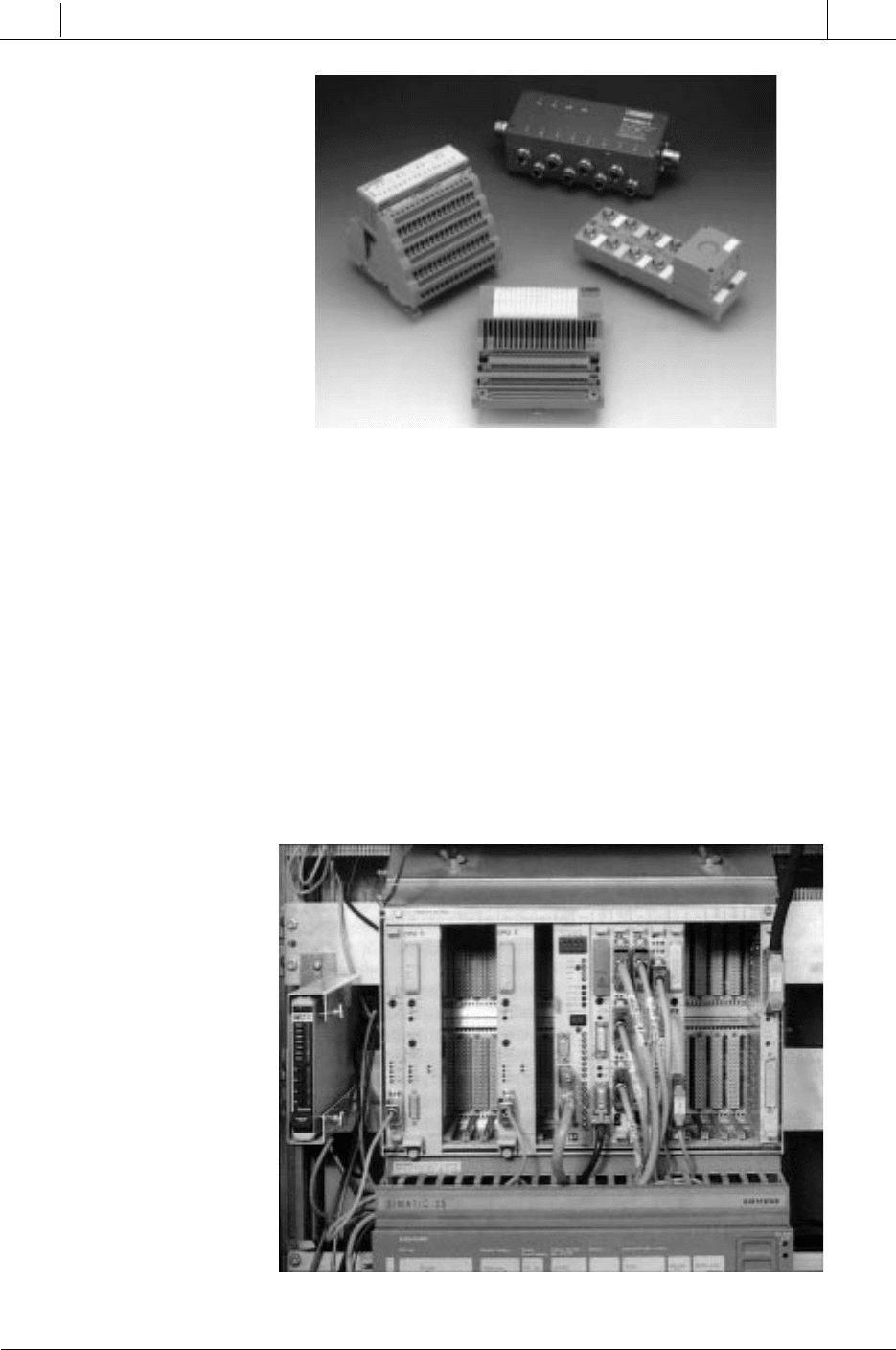
S has built-in I/O interfaces in its 256 possible node components, which also
include terminal block connections for easy I/O interfacing (see Figure 19-7).
This network can handle up to 4096 field I/O devices (depending on the
configuration) at a speed of 500 kbaud with cyclic redundancy check (CRC)
error detection.
19-4 DEVICE BUS NETWORKS
887
CHAPTER
19
I/O Bus
Networks
SECTION
5
Advanced PLC
Topics and Networks
Industrial Text & Video Company 1-800-752-8398
www.industrialtext.com
Figure 19-7. InterBus-S I/O block interfaces.
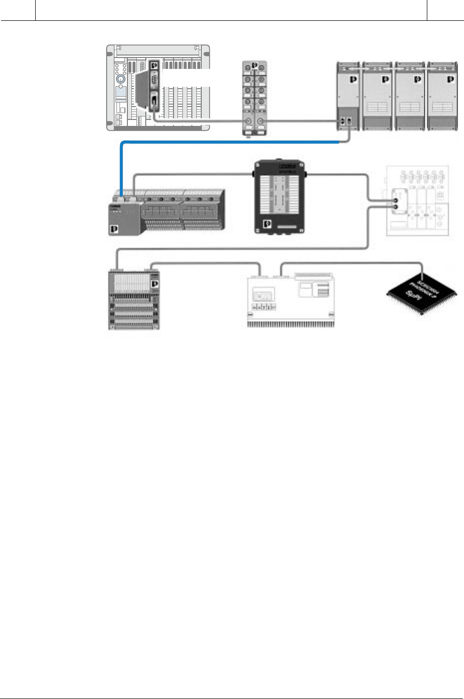
A PLC or computer in an InterBus-S network communicates with the bus in
a master/slave method via a host controller or module (see Figure 19-8). This
host controller has an additional RS-232C connector, which allows a laptop
computer to be interfaced to the network to perform diagnostics. The laptop
computer can run CMD (configuration, monitoring, and diagnostics) soft-
ware while the network is operating to detect any transmission problems. The
software detects any communication errors and stores them in a time-stamped
file, thus indicating when possible interference might have taken place.
Figure 19-9 illustrates a typical InterBus-S network with a host controller
interface to a PLC.
Courtesy of Phoenix Contact, Harrisburg, PA
Figure 19-8. InterBus-S I/O network interface connected to a Siemens PLC.
Courtesy of Phoenix Contact, Harrisburg, PA
888
SECTION
5
Advanced PLC
Topics and Networks
Industrial Text & Video Company 1-800-752-8398
www.industrialtext.com
CHAPTER
19
I/O Bus
Networks
Figure 19-9. An InterBus-S network with a host controller interface to a PLC.
I/O device addresses in an InterBus-S network are automatically determined
by their physical location, thus eliminating the need to manually set ad-
dresses. The host controller interface continuously scans data from the I/O
devices, reading all the inputs in one scan and subsequently writing output
data. The network transmits this data in frames, which provide simultaneous
updates to all devices in the network. The InterBus-S network ensures the
validity of the data transmission through the CRC error-checking technique.
Table 19-1 lists some of the features and benefits of the InterBus-S device bus
network. Note that this network uses the first, second, and seventh layers—
the physical, data link, and application layers, respectively—of the ISO OSI
reference model.
CANbus Byte-Wide Device Bus Networks. CANbus networks are byte-
wide device bus networks based on the widely used CAN electronic chip
technology, which is used inside automobiles to control internal components,
such as brakes and other systems. A CANbus network is an open protocol
system featuring variable length messages (up to 8 bytes), nondestructive
arbitration, and advanced error management. A four-wire cable plus shield—
two wires for power, two for signal transmission, and a “fifth” shield wire—
InterBus-S
Controller Board
InterBus-S
IP-67 (NEMA 4)
Sensor/Actuator
Bus (SAB)
I/O Module for
8 devices
InterBus-S Local Bus Group
Consisting of a Bus Terminal (BT)
Module and Analog/Digital
I/O Modules
InterBus-S
IP-65 (NEMA 12)
Waterproof
I/O Module
InterBus-S
Remote Terminal (RT)
I/O Module
InterBus-S Smart Terminal
Block (ST) Local Bus Group
Third-Party
Pneumatic Manifold Valves
InterBus-S
Protocol Chips Available
for Custom I/O Applications
Third-Party
Drive Control
