Bryan L. Programmable controllers. Theory and implementation
Подождите немного. Документ загружается.

539
CHAPTER
12
PLC System
Documentation
Industrial Text & Video Company 1-800-752-8398
www.industrialtext.com
SECTION
3
PLC
Programming
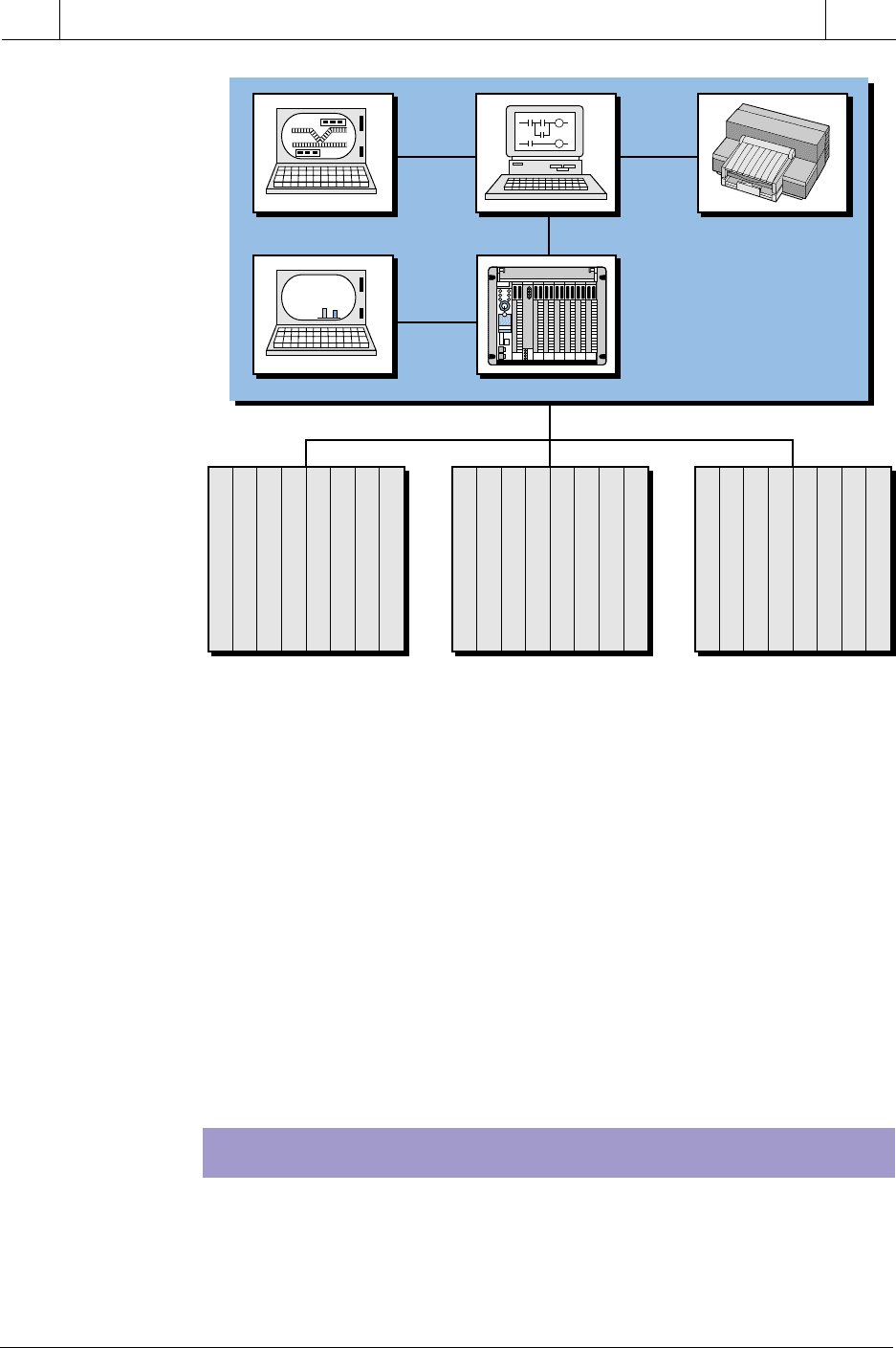
Figure 12-2. System arrangement diagram.
specific I/O devices. For example, during start-up the user can easily
determine that I/O point 0200 (LS, PB, etc.), located in subsystem 02, is
housed in room number 24.
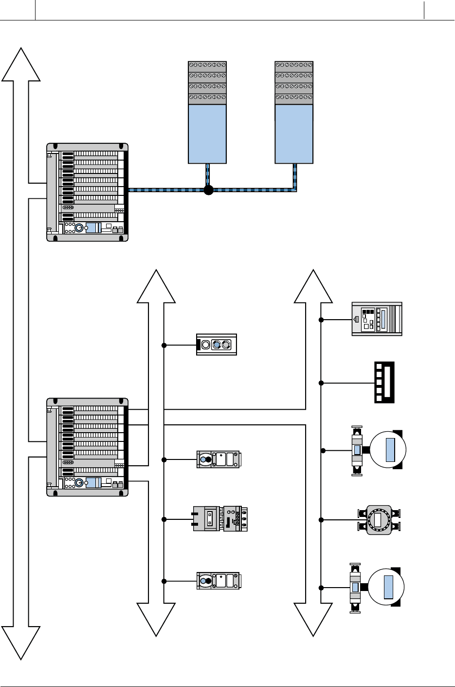
If the programmable controller system involves a network framework with
other components, the system configuration should show a general block
diagram of the whole network (all nodes) and the major devices connected to
it. For example, Figure 12-3 illustrates a PLC-based system in which a
network interfaces with two other networks, a process bus network and a
device bus network. This system configuration diagram immediately gives a
broad picture of the total system.
I/O WIRING CONNECTION DIAGRAM
An I/O wiring connection diagram shows the actual connections of field
input and output devices to the PLC module. This drawing normally
includes power supplies and subsystem connections to the CPU. Figure
PCGUI
GUI
Programmable
Controller CPU
Printer
Control Room
24 VAC Input
24 VAC Input
24 VAC Input
Unused
Unused
24 VAC Output
24 VAC Output
24 VAC Output
115 VAC Input
115 VAC Input
115 VAC Input
115 VAC Input
Unused
115 VAC Output
115 VAC Output
115 VAC Output
0–5 V Analog-In
4–20 mA Analog-In
4–20 mA Analog-In
4–20 mA Analog-In
Unused
Unused
Unused
Unused
64 I/O Rack #00
Points: 00–77
Room #4
64 I/O Rack #01
Points: 100–177
Room #5
64 I/O Rack #02
Points: 200–277
Room #24
20
20
01
00
21
02
Prod
A
345
Prod
B
251
level: A B
A
B
540
SECTION
3
PLC
Programming
Industrial Text & Video Company 1-800-752-8398
www.industrialtext.com
CHAPTER
12
PLC System
Documentation
Figure 12-3. System configuration diagram of a PLC interfacing with process bus and device bus networks.
0
1
2
3
4
5
6
7
0
1
2
3
4
5
6
7
0
1
2
3
4
5
6
7
0
1
2
3
4
5
6
7
Control
Valve
Control
Valve
Flow
Meter
Pressure
Meter
Intelligent
AC Drive
PLC Control Network
Process Bus Network
Device Bus Network
Photoelectric
Switches
Photoelectric
Switches
Motor
Starters
Push Button
Station
0
1
2
3
4
5
6
7
0
1
2
3
4
5
6
7
0
1
2
3
4
5
6
7
0
1
2
3
4
5
6
7
PLC
Subsystem
PLC
Subsystem
541
CHAPTER
12
PLC System
Documentation
Industrial Text & Video Company 1-800-752-8398
www.industrialtext.com
SECTION
3
PLC
Programming
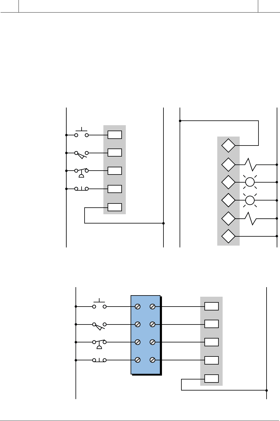
Figure 12-4. I/O wiring connection diagrams for (a) inputs and (b) outputs.
12-4 illustrates an example of an I/O wiring connection diagram. This
diagram shows the rack, group, and module locations of each field device to
illustrate the termination address of each I/O point. If the field devices are
not wired directly to the I/O module, then the diagram should show terminal
block numbers (see Figure 12-5). This way, anyone troubleshooting the PLC
system will know which points to check in the terminal blocks. Good I/O
wiring documentation is invaluable during installation, as well as for later
reference.
Figure 12-5. Input connection diagram indicating terminal block numbers.
L1 L2
PB1
PB5
LS3
PS4
0
1
2
3
C
0120
0121
0122
0123
Common
Rack 01
Group 2
Rack 02
Group 3
Input
Address
(a)
L1 L2
0
1
2
3
Hot (L1)
0230
0231
0232
0233
Common
Output
Address
(b)
AC
Sol 1
C
Sol 2
PL3
PL2
L1 L2
PB1
PB5
LS3
PS4
0
1
2
3
C
0120
0121
0122
0123
Common
Rack 01
Group 2
Input
Address
1
2
3
4
TB2_1
TB_2
TB2_2
TB2_3
TB2_4

542
SECTION
3
PLC
Programming
Industrial Text & Video Company 1-800-752-8398
www.industrialtext.com
CHAPTER
12
PLC System
Documentation
I/O ADDRESS ASSIGNMENTS
Table 12-2. I/O address assignment.
INTERNAL STORAGE ADDRESS ASSIGNMENTS
An internal storage address assignment document is an important part of
the total documentation package. Because internals are used for program-
ming timers, counters, and control relay replacements and are not associated
with any field devices, programmers tend to use them freely, without
accounting for their usage. However, just as with real I/O, misuse of internals
can result in system misoperation.
Good documentation of internals simplifies field modifications during start-
up. For example, imagine a start-up situation involving the modification of
one or more program rungs by adding extra interlocking. For this modifica-
tion, the user must utilize internal coils that are not already assigned. If the
internal I/O address assignment document is current and accurate, showing
both used and unused addresses, the user can quickly locate available internal
addresses. This saves time and avoids confusion. The internal address
assignment document indicates the address, type, and function of each
internal in the program. Table 12-3 illustrates a typical I/O address assign-
ment document for internals.
An I/O address assignment document identifies each field device by
address (rack, group, and terminal), the type of input or output module (e.g.,
115 VAC, 24 VAC), the type of field device (e.g., limit switch, solenoid),
and the function the device performs in the field. Table 12-2 shows a
typical I/O address assignment document. This assignment document is
similar to the I/O assignment table that will be completed prior to developing
the control program.
sserddAepytO/IeciveDnoitcnuF
0210niCAV511BP1BPnottubhsuptratS
1210niCAV511SL2#timilpU
2210niCAV511)CN(SPKOerusserpciluardyH
3210niCAV511)CN(BP2BPteseR
•• • •
•• • •
•• • •
0320tuoCAV42loS1#tcarteR
1320tuoCAV42LPnoitisopni2#
2320tuoCAV42LPgninnuR
3320tuoCAV42loS3#putsaF

543
CHAPTER
12
PLC System
Documentation
Industrial Text & Video Company 1-800-752-8398
www.industrialtext.com
SECTION
3
PLC
Programming
STORAGE REGISTER ASSIGNMENTS
Table 12-3. Internal storage address assignment.
Each available system register, whether a user storage register or an I/O
register, should be properly identified. Most applications use registers to
store or hold information for timers, counters, or comparisons. Keeping an
accurate record of the use of and changes to these registers is very critical.
Just as with I/O assignment documents, the storage register assignment
table should show whether or not a register is being used. Table 12-4 shows
a typical documentation form for register assignments.
Table 12-4. Storage register assignment table.
VARIABLE DECLARATION
In an IEC 1131-3 programming environment (discussed in Chapter 10), the
documentation of the physical I/O addresses, internal storage addresses, and
lanretnIepyTnoitpircseD
0001lioCnoitisophctalotdesU
1001lioCtcatnocremitsuoenatnatsniputeS
2001erapmoClauqePMCrofdesU
3001ddAevitisopnoitiddA
•• •
•• •
•• •
001TremiT1rotom—remityaled-nO
004CretnuoC1#royevnocnoseceiptnuoC
•• •
•• •
•• •
retsigeRstnetnoCnoitpircseD
63031TtupnierutarepmeTeludomgolanahtiwretsigerO/I
04032TtupnierutarepmeTeludomgolanahtiwretsigerO/I
000400213RDTfoteserpces02
10040002=PMCrofteserptnuoC
20040005>PMCrofteserptnuoC
•• •
•• •
•• •
00140 desutoN
ot• •
0024• •

544
SECTION
3
PLC
Programming
Industrial Text & Video Company 1-800-752-8398
www.industrialtext.com
CHAPTER
12
PLC System
Documentation
storage address assignments requires that the devices connected to the PLC
via its I/O be declared, or defined, as variables. Table 12-5 illustrates a typical
variable declaration. A proper variable declaration, which includes the name
of the input, output, or internal, should be included in each of the assignment
documents (e.g., I/O assignment, storage register assignment).
sserddAepyTnoitpircseDemaN_raV
0210NI1BPnottubhsuptratS1BP_TRATS
1210NI2SLhctiwstimilpU2SL_pU
2210NIKOerusserpciluardyHKO_SERP_DYH
3210NI2BPteseR2BP_TESER
•• • •
•• • •
•• • •
0320TUO1LOSdionelostcarteR1LOS_tcarteR
1320TUOnoitisopni2LPthgiltoliP2LP_soP_nI
2320TUOgninnursthgiltoliPLP_NUR
3320TUO3LOSdionelosputsaF3LOS_pU_tsaF
Table 12-5. Variable declaration.
CONTROL PROGRAM PRINTOUT
The control program printout is a hard copy of the control logic program
stored in the controller’s memory. Whether stored in ladder form or some
other language, the hard copy should be an exact replica of the controller’s
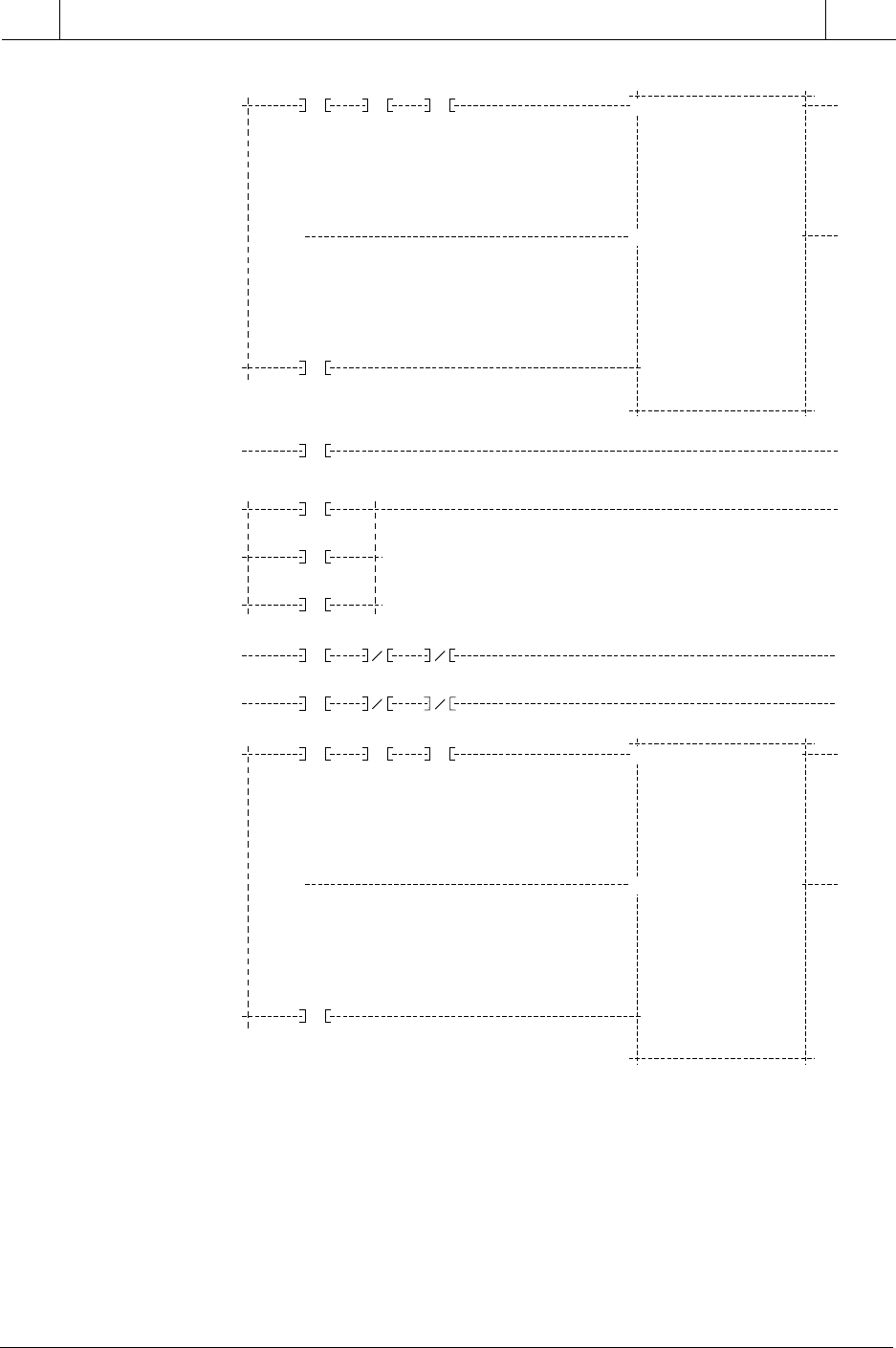
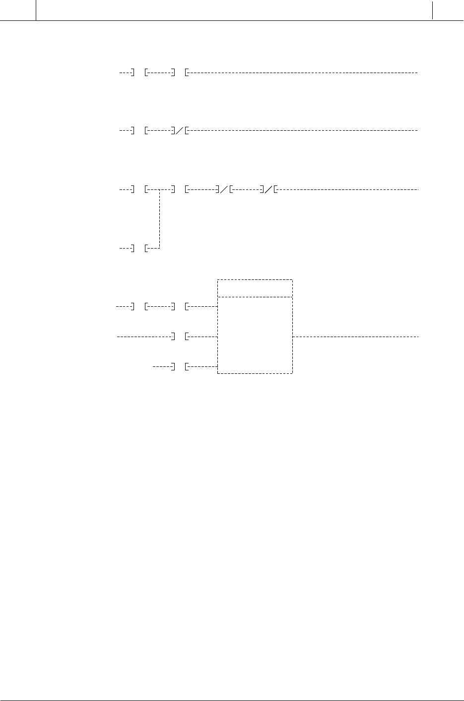
memory. Figure 12-6 shows a typical ladder printout in its basic format.
A basic hard copy printout shows each programmed instruction with the
associated address of each input and output. This printout, however, does
not readily provide information about each instruction’s function or which
field device is being evaluated or controlled. For this reason, the program
coding alone, without the previously mentioned documentation, is not ad-
equate for interpretation of the control system. Most manufacturers provide
a documentation package that allows the programming device, generally a
PC (personal computer), to enter labels or mnemonic nomenclature for the
control program elements.
The extent of the control program printout and documentation varies from
one PLC manufacturer to another. This documentation may or may not
include information pertaining to the input/output connection diagram.
545
CHAPTER
12
PLC System
Documentation
Industrial Text & Video Company 1-800-752-8398
www.industrialtext.com
SECTION
3
PLC
Programming
Figure 12-7 illustrates a ladder control program with generic documented
elements in the ladder rung. Sometimes, only the I/O address number
represents these ladder diagram elements. Most PLC manufacturers’ docu-
mentation allows the user to set global or generic mnemonic comments and
then cross-reference the mnemonics with the inputs and outputs (real and
internal) used in the system.
Figure 12-6. Ladder diagram printout.
( )
70
.01
40
.00
40
.00
40
.00
0
.00
0
.01
+)
+)
( )
41
.00
0
.02
41
.01
2700
.01
( )
40
.01
( )
41
L
.00
0
.12
0
.06
2700
.01
( )
41
U
.00
UP E>=P
E<=P
CNTR
PRESET: 2001
VALUE:
ELAPSED: 2500
VALUE:
RESET
DOWN
( )
70
.01
40
.02
40
.02
0
.02
0
.03
+)
+)
( )
40
.03
UP E>=P
E<=P
CNTR
PRESET: 2002
VALUE:
ELAPSED: 2501
VALUE:
RESET
DOWN
( )
41
.00
0
.03
41
.01
2700
.01
546
SECTION
3
PLC
Programming
Industrial Text & Video Company 1-800-752-8398
www.industrialtext.com
CHAPTER
12
PLC System
Documentation
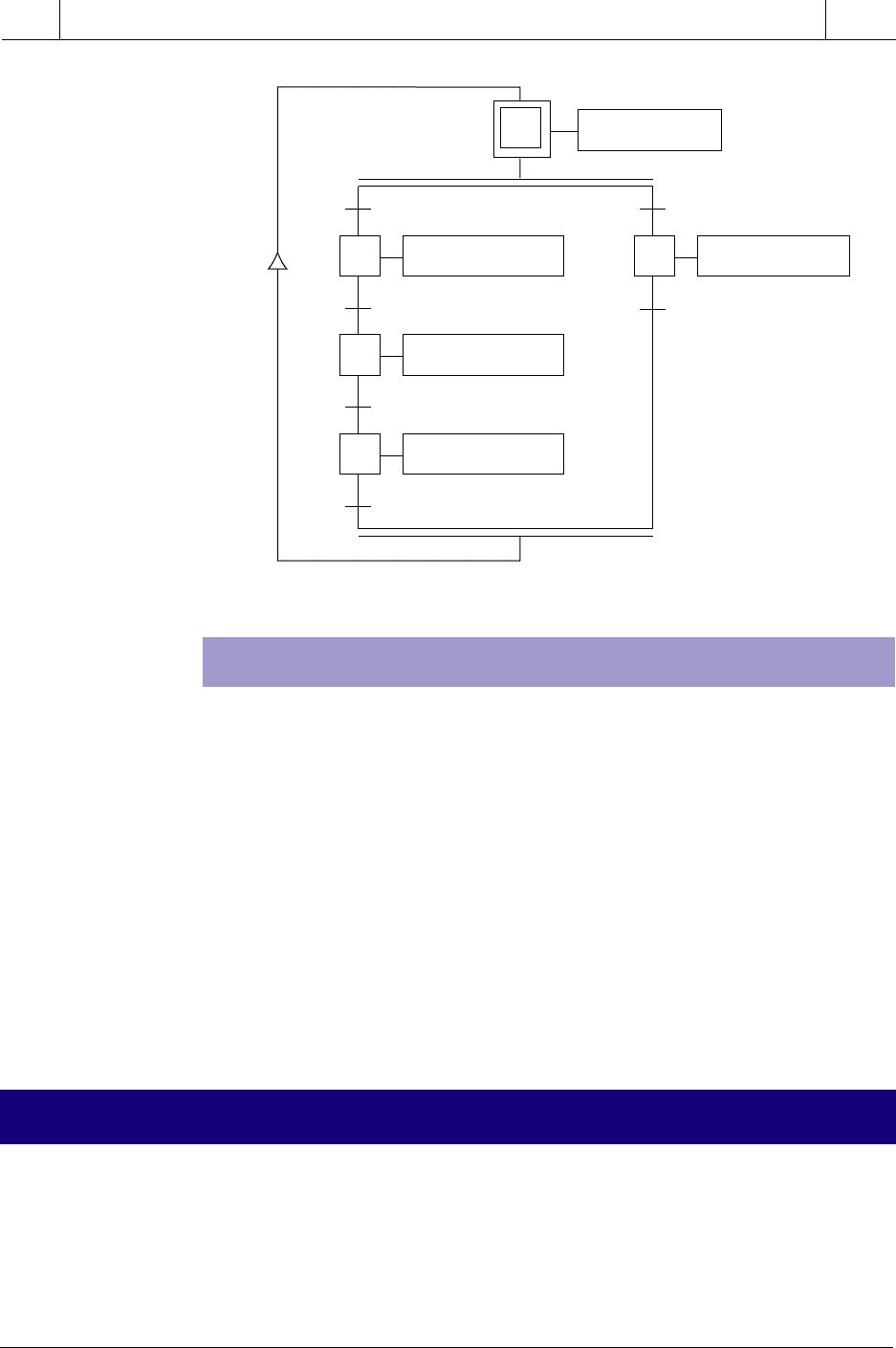
Most IEC 1131 software systems include a documentation package that uses
the defined variables as the labels for the programmed control elements.
These systems also provide a summary of the variable declaration and the
types of variables declared. Figure 12-8 shows a typical IEC 1131 level 1
chart printout.
The controller’s memory always holds the latest software revision of the
program; therefore, the user should have the most recent hard copy when
examining the system. Changes are frequently made to the program during
start-up, so these changes should be immediately documented, even though
this is time consuming. Another good practice is to obtain the latest hard copy
of the program after any field changes have taken place.
Figure 12-7. Ladder control program printout with manufacturer’s documentation.
( )
02
I
I
03
I
I
04
I
I
05
I
I
06
I
I
07
I
I
08
I
I
09
I
I
10
I
I
11
I
I
12
I
I
13
I
I
14
I
I
15
I
I
16
I
ENGAGE EVIS OFFE-STOP
( )
ENGAGE EVIS ONE-STOP
( )
PROX SW ENGAGE ON
( )
0.013
EVIS OFF
EVIS ON
ENGAGE ONEVIS ON
1 SECOND
DELAY POT
AIR PRESS SPD FAIL
SAFETY INTERLOCK FOR ENGAGING
OF REHANGER
ON DELAY TIMER
ACTIVE TON
TICK
F 500
OUTPUT
PRESET
R 600
ELAPSE
1
11
22
Time Delay Is Taken From Pot 2
On The Merge Module. Operator
Can Select From 0-10 Seconds
547
CHAPTER
12
PLC System
Documentation
Industrial Text & Video Company 1-800-752-8398
www.industrialtext.com
SECTION
3
PLC
Programming
Figure 12-8. IEC 1131 level 1 chart printout.
CONTROL PROGRAM STORAGE
For the most part, PLC programming occurs at a location other than where
the controller will finally be installed. For this reason, the user should save the
control program on a storage medium, such as a cassette tape, a floppy
disk, or an electronic memory module. This practice allows the user to send
or carry the stored program to the installation site and reload it into the
controller’s memory quickly. This approach is usually employed when the
system uses a volatile-type memory, but it is also used with nonvolatile
memory for backup purposes.
The reproducible, stored control program, like any other form of documen-
tation, should be kept accurate and current. A good practice is to always have
two copies, in case one is damaged or misplaced. Also, make sure that the
stored program agrees with the latest hard copy of the control logic.
Documentation plays a very important role in the design of any program-
mable controller–based system. This documentation can be a tedious, costly
task requiring several skilled people to implement the many phases of
documentation (e.g., drafting, table preparation, and I/O assignment). There-
fore, as an alternative to creating this time-consuming documentation by
12-3 PLC DOCUMENTATION SYSTEMS
1
20
Acknowledge
30
ErrorRun & Not (Error)
Start Motor M1
21
M1 Started
Start Tempo
22
Tempo > 3s
M1 Stopped
Stop Motor M1
Alarm
Initialize
548
SECTION
3
PLC
Programming
Industrial Text & Video Company 1-800-752-8398
www.industrialtext.com
CHAPTER
12
PLC System
Documentation
hand, several manufacturers in the PLC support industry have developed
sophisticated, yet simple, systems for documenting a total PLC system. These
systems speed up the documentation procedure and reduce the manpower
needed for the task. They increase the total program development productiv-
ity by reducing programming errors and increasing documentation through-
put. In addition to the standard types of documentation previously discussed,
documentation systems even provide several other useful documents.
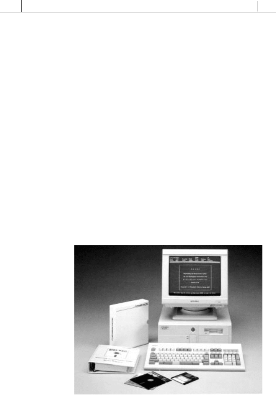
Powerful and popular documentation systems, like the ones shown in
Figure 12-9, offer numerous advantages and cost savings over manual
documentation methods. Some of these advantages are as follows:
• Documentation systems provide electronic cut-and-paste capabili-
ties, macros, copy functions, generic addressing capabilities, and
address exchange functions.
• They provide a multiple-character, wide-field labeling capability for
contacts and elements. In addition to ladder element labels, these
systems also allow unlimited comments to be placed anywhere else
on the ladder drawing.
• These systems provide the capability for a complete range of I/O
elements and hardwired I/O drawings with integrated, automatic
cross-referencing of the logic program.
• Documentation systems can upload and download programs for most
PLC systems.
Figure 12-9. Mitsubishi’s PLC documentation system for A1S series PLCs.
Courtesy of Mitsubishi Electronics, Mount Prospect, IL