Bryan L. Programmable controllers. Theory and implementation
Подождите немного. Документ загружается.

519
CHAPTER
11
System Programming
and Implementation
Industrial Text & Video Company 1-800-752-8398
www.industrialtext.com
SECTION
3
PLC
Programming
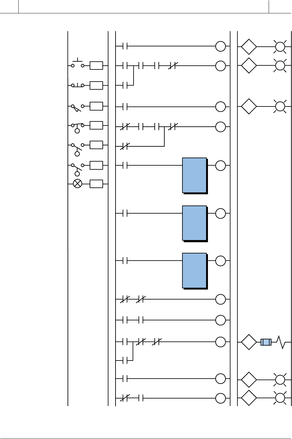
Figure 11-71. PLC implementation of the batching application.
(continued on next page)
L1 L1 L2L2
Start
Stop
Tank in
Positon
000
001
Inputs Program Coding Outputs
002
Tank In Position
010
011
012
Tank LS
002
Tank PL
010
Empty LS
003
005
Set to T1
1000
CMP
High 1
1001
Empty PL
012
SOL1
013
003
034
Start
000
Start
System
011
Stop
001
Tank LS
002
SOL3
023
Start Mix PL
011
SOL1
013
Valve 1
Open PL
014
M1
021
Empty LS
003
Start
System
011
Empty
LS
003
Ready
to Mix
1006
Set to T1
1000
Ready
to Add
1005
LLS1
004
SOL3
023
SOL1
013
Valve 1 Open
014
Finish Ingr. A
015
013
SOL1
Valve
Empty
004
LLS1
LLS2
Temp
CMP>
3034
>
4000
Set to T1
1000
CMP
Range OK 1
1002
LIM
4000
3034
4002
Set to T1
1000
CMP
Low 1
1003
CMP<
3034
<
4003
Temp
High 1
1001
Temp
Low 1
1003
Temp
OK 1
1004
Range
OK 1
1002
Start
System
011
Ready
to add
1005
LLS1
004
SOL1
013
Fin A
015
Start Mix
(System)
Empty
Start System/
520
SECTION
3
PLC
Programming
Industrial Text & Video Company 1-800-752-8398
www.industrialtext.com
CHAPTER
11
System Programming
and Implementation
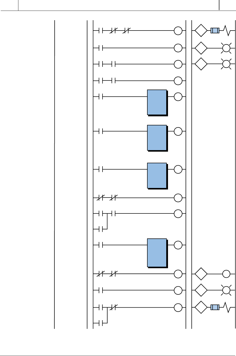
Figure 11-71 continued.
(continued on next page)
Mix CMD
1013
SOL2
016
Valve 2 Open
PL017
Fin A
015
LLS2
005
SOL3
023
SOL2
016
Valve 2 Open
Finish Ingr. B
016
SOL2 Valve
023
SOL3 Valve
017
020
021
022
Ready to Mix
1006
CMP High 2
1007
CMP>
3034
>
4004
Ready to Mix
1006
CMP
Range OK 2
1010
LIM
4005
3034
4006
Ready
to Mix
1006
CMP
Low 2
1011
CMP<
3034
<
4007
Mix CMD
1013
Mix
20 Min
2000
M1
021
PL Mixer ON
022
TMR
4100
(1200)
4101
1 sec.
LLS2
005
SOL2
016
Fin B
020
Fin B
020
Fin A
015
Ready to Mix
1006
Temp
Low 1
1011
Temp
High 1
1007
Temp
OK 2
1012
Mix
CMD
1013
Mix
20 min
2000
Mix
20 min
2000
Empty
LS
003
M1
021
SOL3
023
Discharge SOL3
023
Range
OK 2
1010
Ready
to Mix
1006
Mix CMD
1013
Mixer ON
M1
Mixer
Motor
521
CHAPTER
11
System Programming
and Implementation
Industrial Text & Video Company 1-800-752-8398
www.industrialtext.com
SECTION
3
PLC
Programming
11-7 SHORT PROGRAMMING EXAMPLES
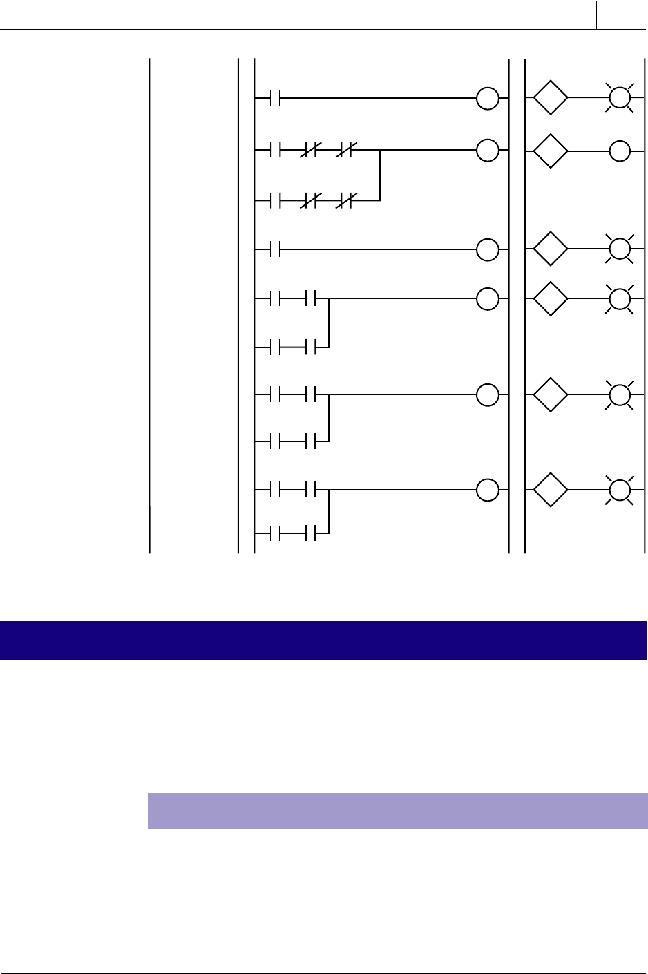
Figure 11-71 continued.
EXAMPLE 1: INTERNAL STORAGE BITS
This section presents several examples of logic series that are often encoun-
tered when programming a controller. For convenience, the examples are
implemented using the most basic ladder diagram instructions. Therefore,
they may require more instructions than they would if they were pro-
grammed using a higher level instruction set.
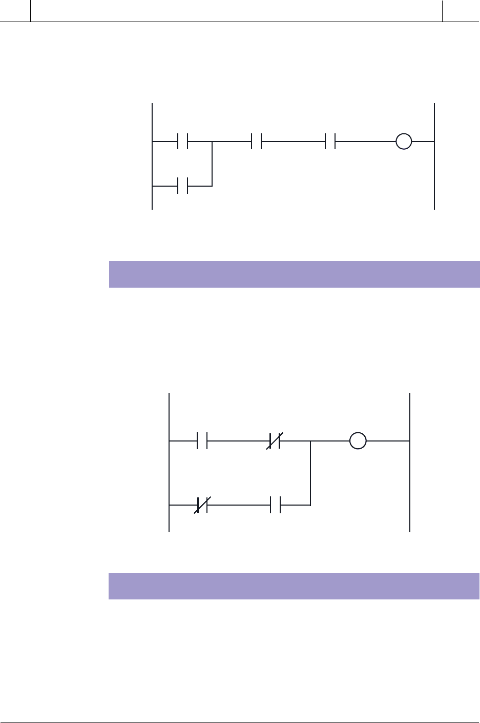
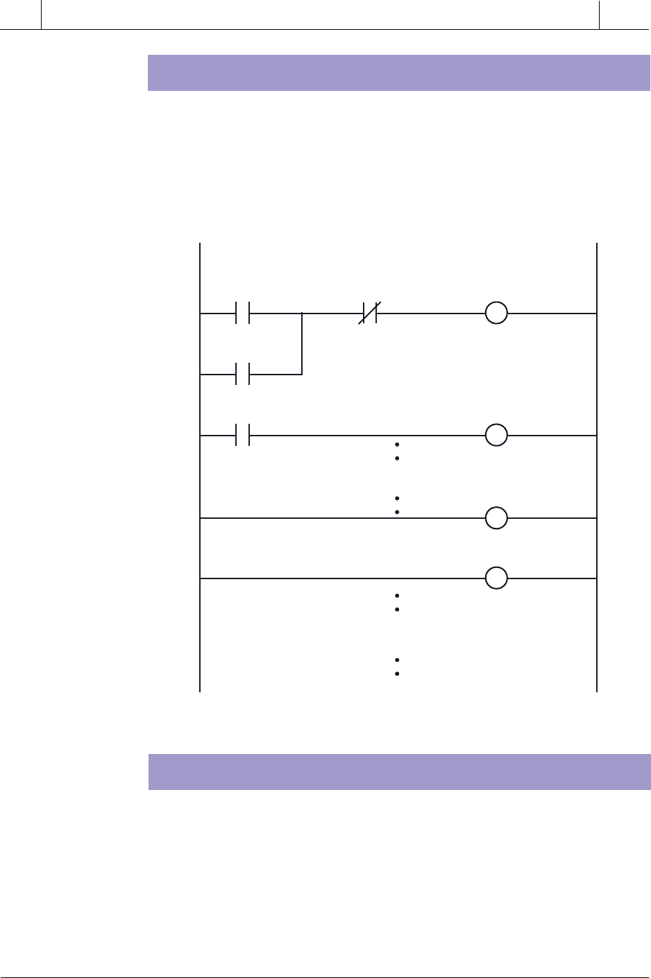
Most programming devices are limited in the number of series contacts or
parallel branches that a rung can have. This limitation can be overcome
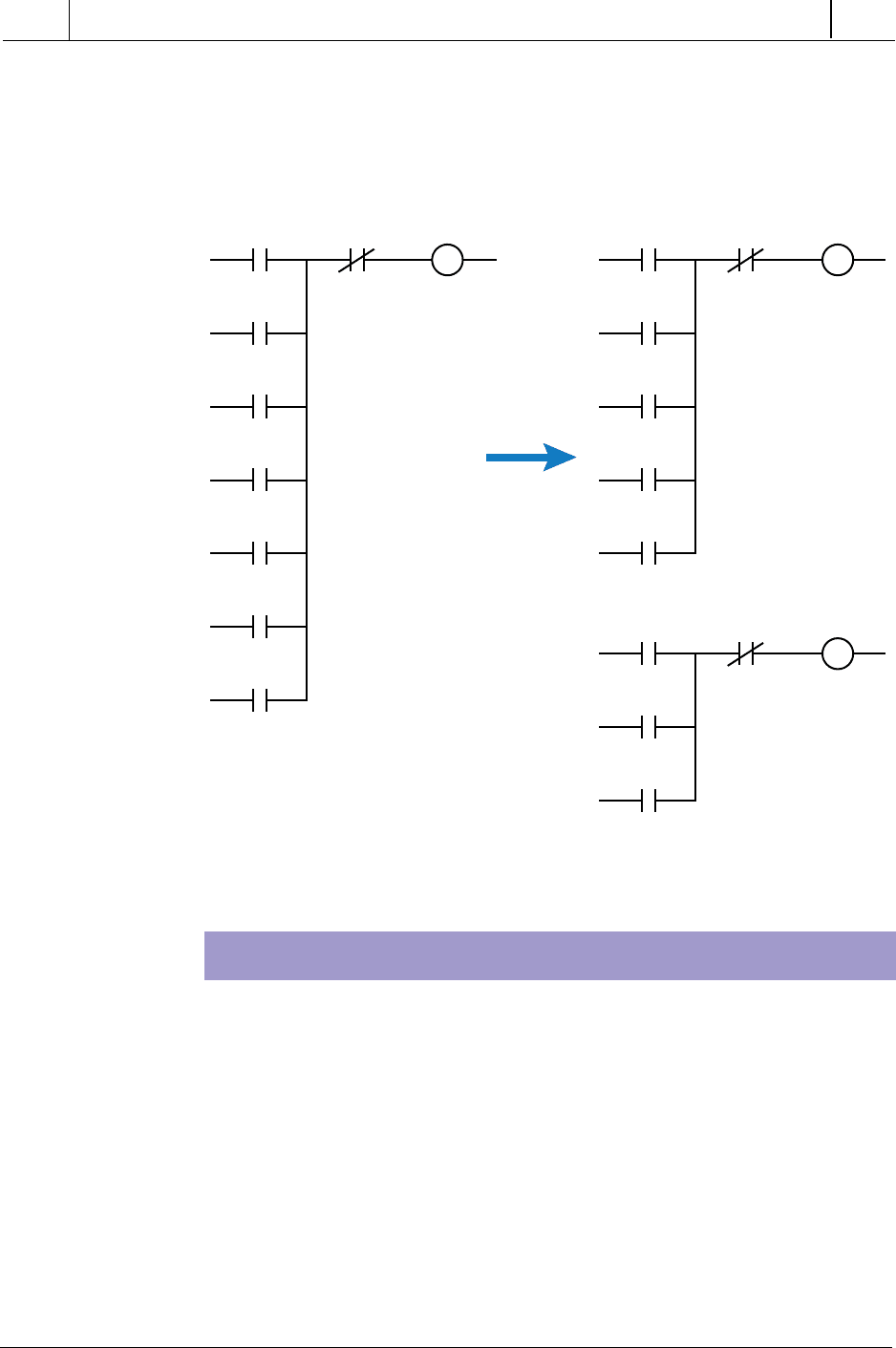
through the use of internal storage bits. Figure 11-72a illustrates a PLC
program that was translated directly from a hardwired relay diagram that
requires seven parallel OR branches. If the programmable controller had
Set to
T1
1000
CMP
High 1
1001
CMP
Low 1
1003
Heat
025
Ready
to Mix
1006
CMP
High 2
1007
CMP
Low 2
1011
024
SOL3
023
Valve 3
Open PL
024
Heat
025
PL Heater ON
026
CMP
High 1
1001
Set to
T1
1000
Ready
to Mix
1006
CMP
High 2
1007
PL Temp High
027
025
H
Heater
Valve 3 Open
026
027
Heater ON
Temp High
CMP
Low 1
1003
Set to
T1
1000
Ready
to Mix
1006
CMP
Low 2
1011
PL Temp Low
030
030
Temp Low
Temp
OK 1
1004
Set to
T1
1000
Ready
to Mix
1006
Temp
OK 2
1012
PL Temp OK
031
031
Temp OK
522
SECTION
3
PLC
Programming
Industrial Text & Video Company 1-800-752-8398
www.industrialtext.com
CHAPTER
11
System Programming
and Implementation
Figure 11-72. (a) A relay circuit using seven rungs that is (b) converted to five rungs
using an internal.
only allowed five OR branches, an internal could have been used to break
the circuit into two circuits, as shown in Figure 11-72b. The program’s
operation is the same in both configurations. This technique would also be
valid if the contacts were arranged in series.
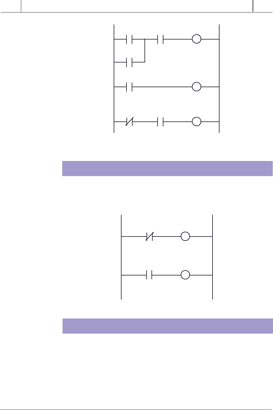
EXAMPLE 2: START/STOP CIRCUIT
The start/stop circuit shown in Figure 11-73 can be used to start or stop a motor
or process or to simply enable or disable some function. To start a motor, the
ladder output only needs to reference the motor output address. If the intent
of the circuit is to detect that some process is enabled, the output can be
referenced with an internal address.
In Figure 11-73, the stop push button and emergency stop inputs are pro-
grammed as normally open. They are programmed this way because these
types of inputs are usually wired normally closed. As long as the stop push
button and the emergency stop push button are not pushed, the programmed
contacts will allow logic continuity. Since the start push button (normally
1 10 100
2
3
4
5
6
7
1 10 Internal
2
3
4
5
10 100Internal
6
7
(a)
(b)
523
CHAPTER
11
System Programming
and Implementation
Industrial Text & Video Company 1-800-752-8398
www.industrialtext.com
SECTION
3
PLC
Programming
Figure 11-73. Start/stop circuit.
Figure 11-74. Exclusive-OR circuit.
open) is a momentary device (i.e., it allows continuity only when pressed), a
contact from the motor output is used to seal the circuit. Often, the seal-in
contact is an input from the motor starter contacts.
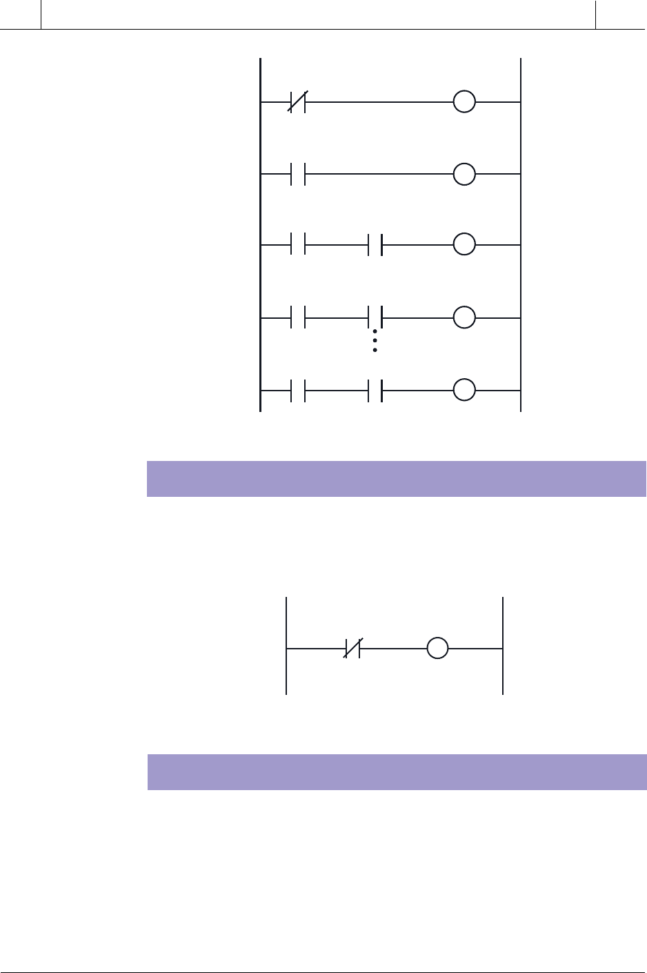
EXAMPLE 3: EXCLUSIVE-OR CIRCUIT
The exclusive-OR circuit in Figure 11-74 is used to prevent an output from
energizing if two conditions, which can activate the output independently,
occur simultaneously. Thus, if either input A or B is activated, the output will
be energized. However; if both are activated, the output will not be
energized.
EXAMPLE 4: ONE-SHOT SIGNAL
The one-shot (transitional output) signal in Figure 11-75 is a program-
generated pulse output that, when triggered, is ON for the duration of one
program scan and then turns OFF. A momentary signal (e.g., a push button)
or an output that comes ON and stays ON for some time (e.g., a motor) can
enable a one-shot signal. Whichever input signal is used, the leading-edge
(OFF-to-ON) transition of the input signal triggers the one-shot signal,
*Wired NC
Start PB Stop PB*
Emergency
Stop PB*
Motor M1
Output
M1
Input
A
Input
B
Input
A
Input
B
Output or Internal

524
SECTION
3
PLC
Programming
Industrial Text & Video Company 1-800-752-8398
www.industrialtext.com
CHAPTER
11
System Programming
and Implementation
which stays ON for one scan and then goes OFF. The signal remains OFF
until the trigger is activated, causing it to come ON again. Clear or reset
signals are typically one-shot signals; the one-shot signal is perfect for this
application, since it stays ON for only one scan.
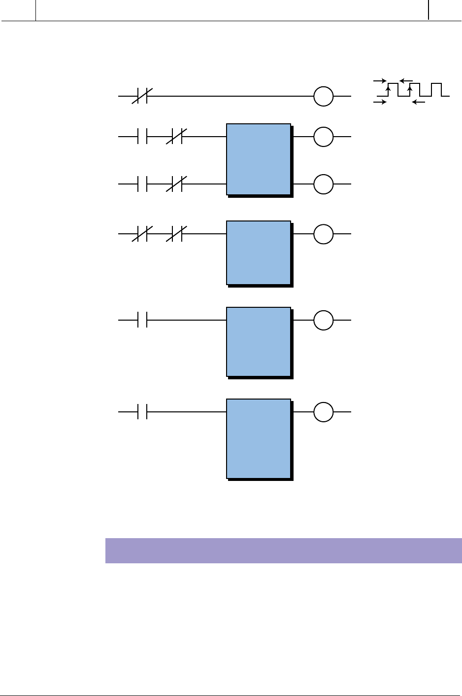
Figure 11-76. (a) A trailing-edge one-shot output circuit and (b) its corresponding
timing diagram.
Figure 11-75. One-shot output circuit.
EXAMPLE 5: TRAILING-EDGE ONE-SHOT SIGNAL
A trailing-edge one-shot signal (see Figure 11-76) generates a pulse with a
one-scan duration. This signal reacts like the one-shot signal in Example 4;
however, the trigger for this pulse is the trailing edge of the trigger pulse.
Figure 11-76 shows the timing diagram for each element’s activation.
A B
C
A
B
B
C
B
OS
(a)
(b)
Trigger
Input Internal 1
Trigger
Input
Internal 1
One-Shot
Output
525
CHAPTER
11
System Programming
and Implementation
Industrial Text & Video Company 1-800-752-8398
www.industrialtext.com
SECTION
3
PLC
Programming
Figure 11-77. Initialization circuit using an MCR.
EXAMPLE 7: SYSTEM START-UP HORN
A start-up horn logic circuit (see Figure 11-78) is used to signal that moving
equipment (e.g., conveyor motors) is about to start. The setup output signal
in this example is similar to a start/stop circuit; but instead of starting the
system, it enables the timer, allowing the horn to sound for 10 seconds. The
horn sounds when the start input is closed and stops when the timer times out
or the reset input opens. The system can start, if the setup signal remains ON,
when the horn delay timer times out.
EXAMPLE 6: INITIALIZATION USING AN MCR
The logic circuit shown in Figure 11-77 can be used to set up parameters
during an initialization period. These parameters include timer and counter
preset values, high- and low-limit set point values, and any other preset or
starting values. Typically, the initialization period occurs only once during
the program, either when the system is first powered up or when power is
restored after a power loss.
Initialize Internal Reset Internal 1
MCR
MCR
Internal Reset
END
Main
Program
Internal 1
Internal 1
Initialization
Routine
526
SECTION
3
PLC
Programming
Industrial Text & Video Company 1-800-752-8398
www.industrialtext.com
CHAPTER
11
System Programming
and Implementation
EXAMPLE 8: OSCILLATOR CIRCUIT
An oscillator logic circuit (see Figure 11-79) is a simple timing circuit that
generates a periodic output pulse of any duration. The TMR1 output
generates this pulse.
Figure 11-79. Oscillator circuit.
EXAMPLE 9: ANNUNCIATOR FLASHER CIRCUIT
A flasher circuit (see Figure 11-80) toggles an output ON and OFF
continually. In this circuit, an oscillator circuit output (TMR1) is pro-
grammed in series with an alarm condition. As long as the alarm condition
is TRUE, the annunciator output will flash. The output in this case is a pilot
light; however, this same logic could be used in conjunction with a horn,
which would pulse during the alarm condition. Any number of alarm
conditions can be programmed using the same flasher circuit.
Figure 11-78. Start-up horn circuit.
Start Reset *
* Wired NC
Horn Output
PR: 10
TB: 1 sec.
Setup
Setup
Setup
Setup
TMR1
TMR1
PR: 5
TB: 0.1 sec.
PR: 5
TB: 0.1 sec.
TMR1
TMR1
TMR2
TMR2
527
CHAPTER
11
System Programming
and Implementation
Industrial Text & Video Company 1-800-752-8398
www.industrialtext.com
SECTION
3
PLC
Programming
Figure 11-80. Annunciator flasher circuit.
EXAMPLE 10: SELF-RESETTING TIMER
The self-resetting timer shown in Figure 11-81 provides a one-scan pulse each
time the timer is energized. The specified preset value of the timer determines
the repetition of this pulse.
Figure 11-81. Self-resetting timer circuit.
EXAMPLE 11: SCAN COUNTER
The circuit shown in Figure 11-82 computes scan time. This short program
counts the number of times two consecutive scans occur during a time
interval, which is defined by the timer (e.g., 10 seconds). Once the time
interval elapses, the program multiplies the number of two-scan counts by
two. It then divides the time interval (10 seconds) by the number of total
scans, thus computing the scan time, which is stored in a result register. The
result register is scaled so that the scan time is expressed in milliseconds.
Alarm
Cond. 1
Alarm 2
Output
Alarm
Cond. 2
Alarm n
Output
Alarm
Cond. n
Alarm 1
Output
n
n
TMR1
TMR2
TMR1
TMR2
TMR1
TMR1
TMR1
PR: 30
TB: 1 sec.
TMR1 TMR1
528
SECTION
3
PLC
Programming
Industrial Text & Video Company 1-800-752-8398
www.industrialtext.com
CHAPTER
11
System Programming
and Implementation
EXAMPLE 12: SEQUENTIAL MOTOR STARTING
This example (see Figure 11-83) illustrates how several motors or other
devices can be started sequentially, as opposed to all at once. For simplicity,
we used an ON-delay timer to delay the start of each motor. However, this
approach is impractical for starting a large number of motors. If a large
number of motors will be started, other techniques that do not require as
many timers as motors (e.g., shift registers, self-resetting timers, oscillator
circuits, etc.) should be used.
Figure 11-82. Scan counter circuit.
AA
AB
D
CTR
PR: K10000
AR: 4000
Up
Reset D
D
TMR
PR: K1000
AR: 4100
TB: 0.01
DE
MULT
R 4000
x
R K2
=
R 4001
DF
DIV
R 4100
÷
R 4001
=
R 4002
Scale +3
Reset C
D
Reset =
One
Scan
Two
Scans