Bryan L. Programmable controllers. Theory and implementation
Подождите немного. Документ загружается.


509
CHAPTER
11
System Programming
and Implementation
Industrial Text & Video Company 1-800-752-8398
www.industrialtext.com
SECTION
3
PLC
Programming
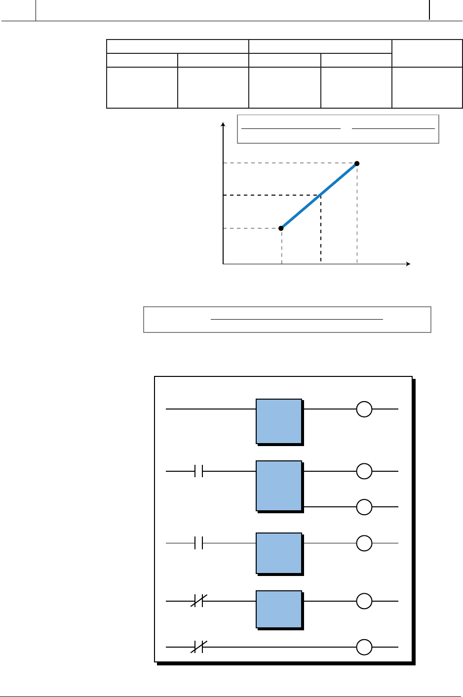
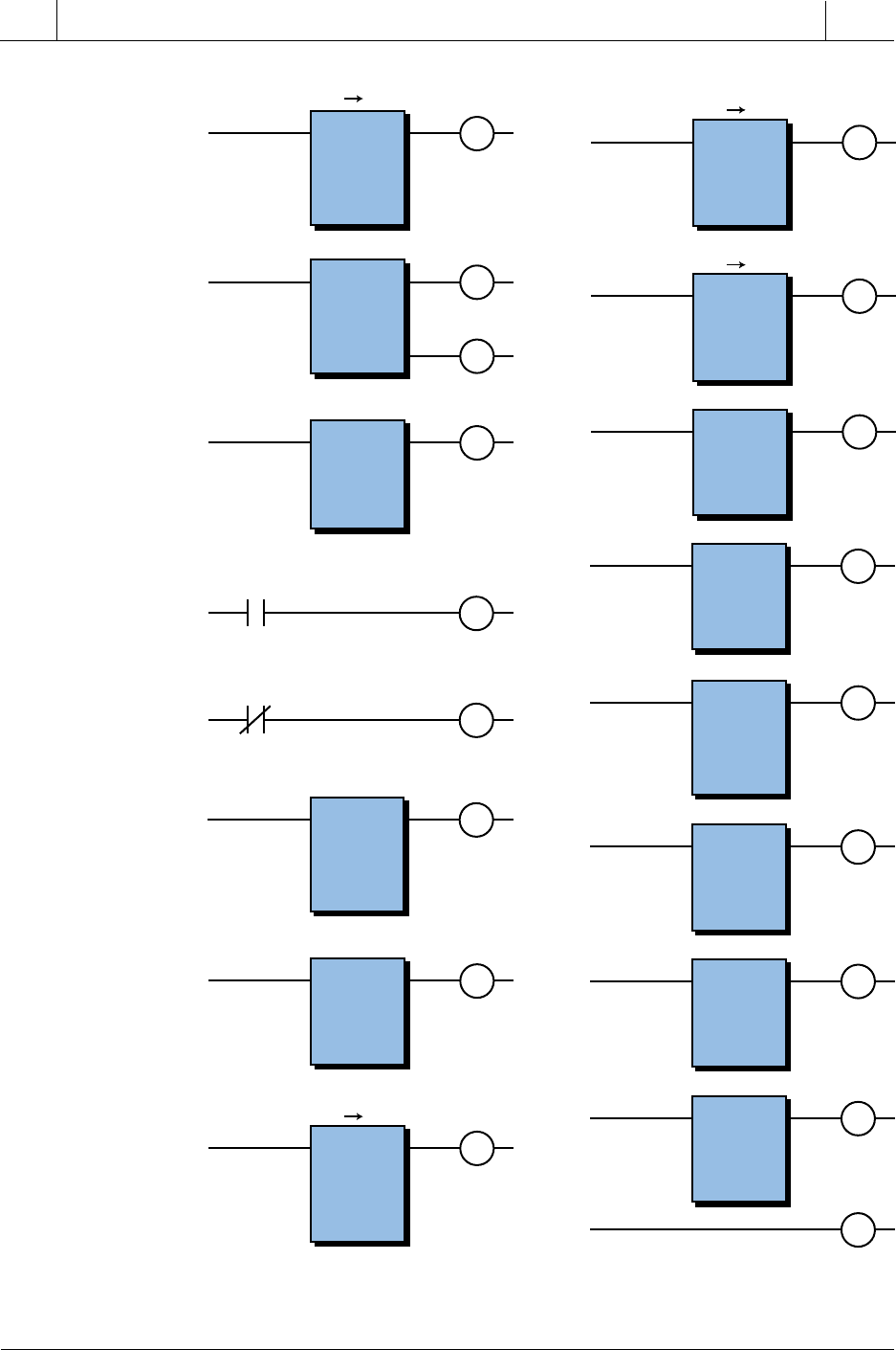
Table 11-31. Internal output assignment.
Figure 11-64 shows the method used to interpolate psi values based on the
contents of each register used. The PLC program shown in Figure 11-65
implements the linear interpolation by finding the high and low counts and
psi values. Using the two pointers, the PLC obtains the high and low values
for the counts and psi through table-to-register instructions. The PLC pro-
gram compares its current analog counts with the count values in the table
registers to find a table location with a greater value. This comparison starts
with the lowest count values in the table. If the actual value (analog counts)
is more than the value pointed to by the pointer, the PLC increments the
pointer (adds 1) and tests a new table value. Once the program finds a register
in the table that contains a value greater than the analog reading, it stores the
pointer value associated with this register in register 4050, thus pointing to the
register at pointer P in Figure 11-64. Then, the value contained in register
4050 is decreased by one and stored in register 4000 to point to the register
at point P – 1 in Figure 11-64. These two registers (4000 and 4050) point to
the low psi/low counts and high psi/high counts, respectively, which will be
used to complete the interpolation.
In the software program presented, we have considered that the actual count
value may be 0 counts. When the count value is 0, the equivalent psi is 0
and the program does not perform the subroutine shown in Figure 11-66. If
it did perform the subroutine, the program would enter into a loop error.
lanretnI noitpircseD
0001 delbanerefsnartgolanA
1001 stnuoc0=tupniroferapmoC
2001 0erastnuoctupnI
3001 retsigerispdetupmocot0tnatsnocevoM
4001 )delbane(retniopsa2tnatsnocevoM
•
•
•
0011 retsigerotelbatevom,noitalopretnibusoG
1011 delbaneerapmoC
2011 stnuochgiH ≥ )stchgiH(stnuoctupni
3011 delbaneretniop)DDA(tnemercnI
•
•
•
0021 retnioperots,htametaluclacotoG
1021 delbaneretniopmorf1tcartbuS
2021 )stcwoL(delbaneretsigerotelbatevoM
3021 )ispwoL(delbaneretsigerotelbatevoM
4021 )isphgiH(delbaneretsigerotelbatevoM
5021 delbanetcartbuS
6021 delbanetcartbuS
7021 delbaneylpitluM
0121 delbanetcartbuS
1121 delbaneediviD
2121 delbaneddA
510
SECTION
3
PLC
Programming
Industrial Text & Video Company 1-800-752-8398
www.industrialtext.com
CHAPTER
11
System Programming
and Implementation
Figure 11-64. Interpolation method.
Figure 11-65. Main program.
(psi)
4450 points to high psi
4150 holds computed psi
4400 points to low psi
Counts
psi
Register
P – 1
P
Low
Counts
Actual
Counts
High
Counts
4500Count Register 4100 4550
Actual Counts – Low Counts
High Counts – Low Counts
Computed psi – Low psi
High psi – Low psi
=
(Actual Counts – Low Counts)(High psi – Low psi)
High Counts – Low Counts
+ Low psiComputed psi =
isp elbaT stnuoC elbaT
retnioP
retsigeR stnetnoC retsigeR stnetnoC
retsigeR
0044 ispwoL 0054 stnuocwoL 1–P@0004
0514 ispdetupmoC 0014 stnuoclautcA
0544 isphgiH 0554 stnuochgiH P@0504
XFER IN
psi read
1000
Slot 7
Rack 0
Reg 4100
Length 1
psi read
1000
CMP =
CMP 0 counts
1001
psi = 0 counts
1002
psi = 0 counts
1002
Sub interpolation
GO SUB 1100
Reg 4100
=
Reg K 0
psi = 0 counts
1002
MOVE
psi Reg = 0
1003
Reg K0
Reg 4150
Length 1
psi = 0 counts
1002
MOVE
Pointer P – 1 = 2
1004
Reg K2
Reg 4000
Length 1
511
CHAPTER
11
System Programming
and Implementation
Industrial Text & Video Company 1-800-752-8398
www.industrialtext.com
SECTION
3
PLC
Programming
Figure 11-66. Interpolation subroutine.
(continued at right)
High Cts ≥ input Cts
1102
Subroutine
1100
High Cts ≥ Input Cts
1102
Found High Psi
Go To 1200
Reg 3000
Length 1
Pointer
4000
Reg 4550
High Cts ≥ Input Cts
1102
Go To
1100
MOVE
TBL REG
MOVE
TBL REG
Done
1101
Reg 4550
≥
Reg 4100
CMP
Inc Pointer P – 1
1103
Reg 4000
+
Reg K1
=
Reg 4000
ADD
Store High Pointer P
1200
Reg 4000
Reg 4050
Length 1
MOVE
Store Pointer P – 1
1201
Reg 4000
–
Reg K1
=
Reg 4000
SUB
Get Low Cts for P – 1
1202
Reg 3000
Length 1
Pointer
4000
Reg 4500
MOVE
TBL REG
MOVE
TBL REG
Get Low Psi
for P – 1
1203
Reg 3100
Length 1
Pointer
4000
Reg 4400
Get High Psi
for P
1204
Reg 3100
Length 1
Pointer
4050
Reg 4450
Input Cts –
Low Cts
1205
Reg 4100
–
Reg 4500
=
Reg 4600
SUB
High Psi –
Low Psi
1206
Reg 4450
–
Reg 4400
=
Reg 4601
SUB
Numerator
Multiplication
1207
Reg 4601
x
Reg 4600
=
Reg 4602
Scale 0
MULT
High Cts –
Low Cts
1210
Reg 4550
–
Reg 4500
=
Reg 4603
SUB
Numerator
multiplication
1211
Reg 4602
÷
Reg 4603
=
Reg 4604
Scale 0
DIV
Result +
Low Cts
1212
Return
Reg 4604
+
Reg 4400
=
Reg 4150
ADD
512
SECTION
3
PLC
Programming
Industrial Text & Video Company 1-800-752-8398
www.industrialtext.com
CHAPTER
11
System Programming
and Implementation
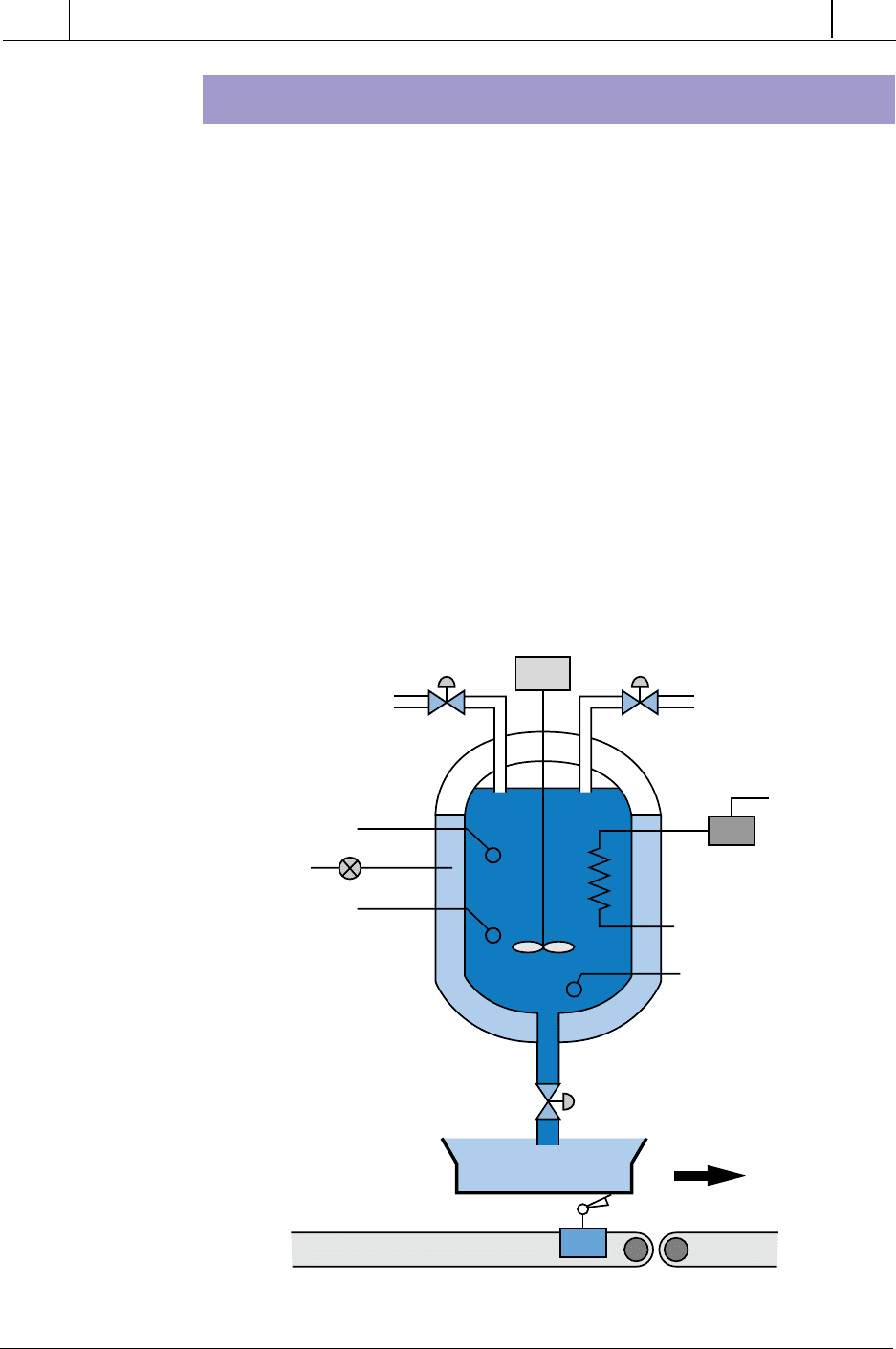
LARGE BATCHING CONTROL APPLICATION
This example explains the automation of a large batching process. It
includes the process description, controller requirements, flowchart, logic
diagrams for each output sequence, assignment of I/O, and program coding.
Figure 11-67 shows the process flow diagram illustrating the elements this
batching application will control. Two ingredients, A and B, will be mixed in
the reactor tank. The reactor tank must be empty (indicated by the normally
closed liquid level switch LLS) and at a temperature of 100°C before
ingredient A can be added. The mixer motor must be off to avoid liquid
precipitation, and the finished product tank should be in a set position, which
the limit switch detects.
Once the reactor tank reaches an initial temperature of 100°C, the controller
will add ingredient A by opening solenoid valve 1 (SOL1) until 100 gallons
of ingredient A have been poured into the tank. LLS1, which is normally open,
detects the quantity of ingredient A in the tank. This switch closes when
ingredient A reaches the proper level. At this point, the controller will add
Figure 11-67. Process flow diagram of the batching application.
Finished Product
Tank
SOL1
Valve
SOL2
Valve
Mixer
Motor M1
Level Switch
LLS2
Level Switch
LLS1
Temp
Empty LLS
Switch (NC)
Heater
SOL3
Valve
LS Tank Position

513
CHAPTER
11
System Programming
and Implementation
Industrial Text & Video Company 1-800-752-8398
www.industrialtext.com
SECTION
3
PLC
Programming
ingredient B by opening SOL2. LLS2 detects the quantity of ingredient B,
which should be 400 gallons. The temperature should be at 100°C ± 10%
during the Add Ingredients step. If the temperature drops, the PLC will turn
ON the heater automatically while the process continues.
When the reactor tank contains both ingredients, the controller will raise the
temperature to 300°C ± 10% and turn ON the mixer for 20 minutes. The
PLC will control the temperature automatically at predefined set points
during the process.
SOL3 will activate the drain valve when the mixing is completed. This
operation will reset the process until another finished product tank is placed
in position, and the cycle starts again. The system should incorporate pilot
light indicators to alert the operator to the status of the batching process.
This application must be capable of reading analog signals from the process.
In this case, the voltage comes from a temperature transducer (0–10 volts),
which has a range of 0 to 500°C (50°C/volt). The heater coil’s ON/OFF
control switch controls the temperature. The application also requires stan-
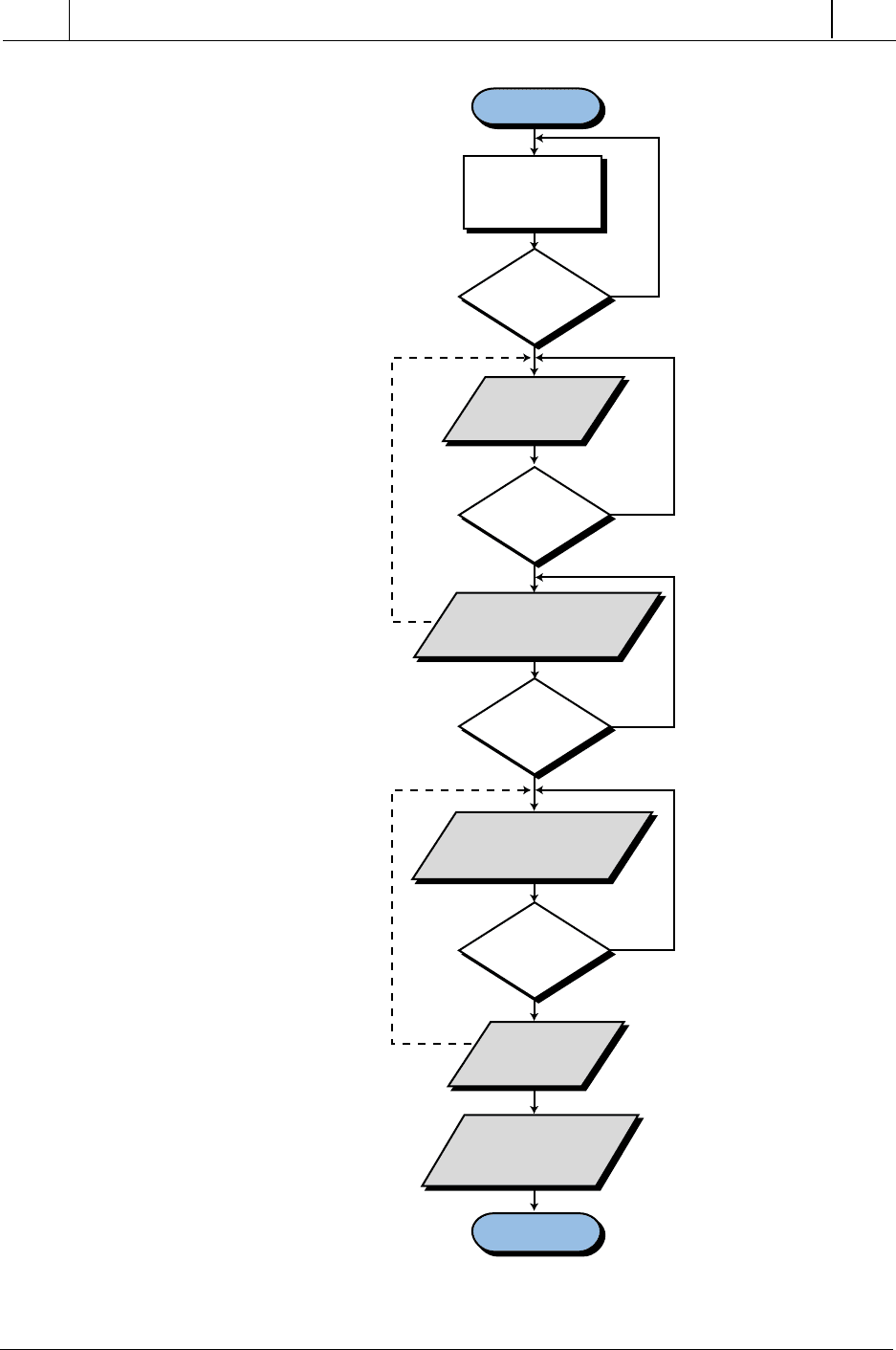
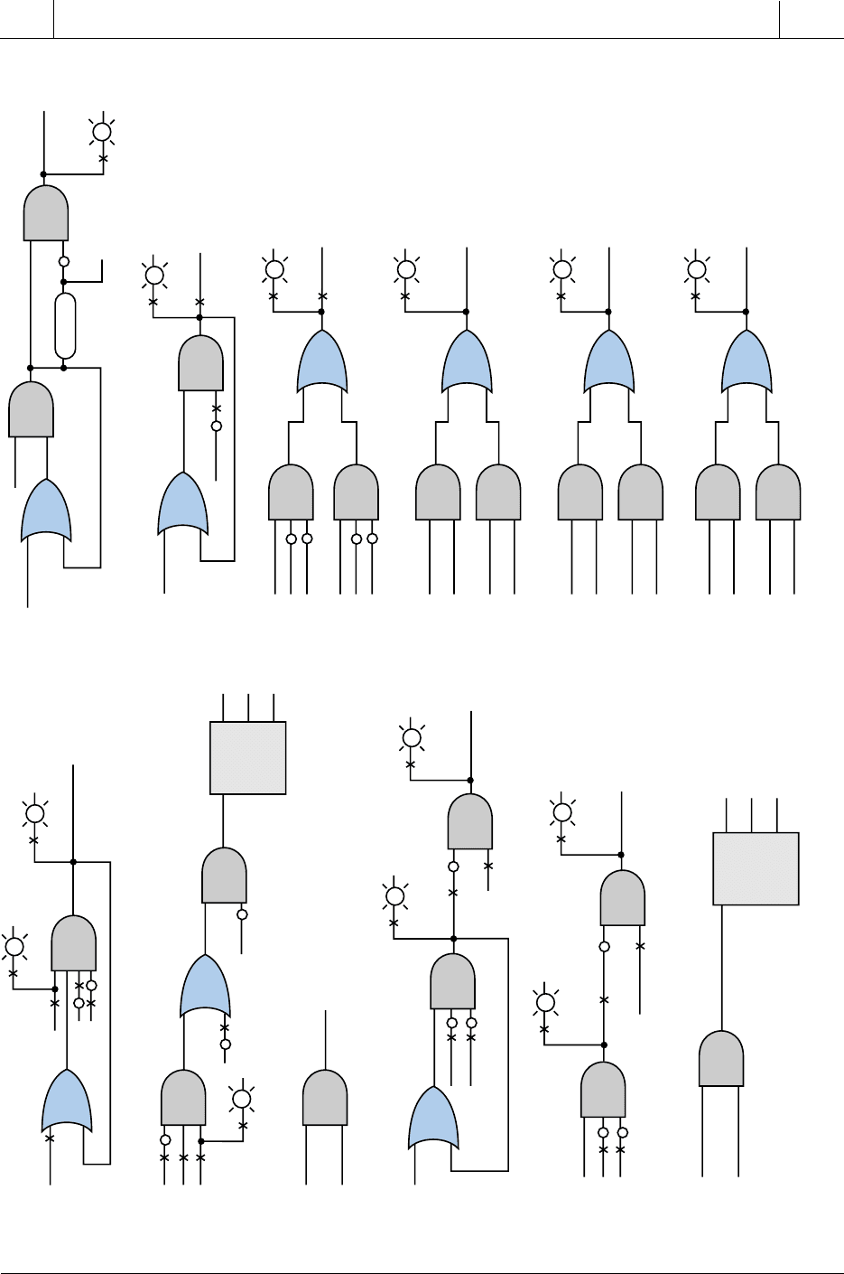
dard 110 VAC input and output modules. Figure 11-68 shows a flowchart of
this process. It illustrates what has been described in the control task
definition and serves as a preparation for the logic diagrams.
Figure 11-69 shows the logic diagrams for this example. The logic diagrams
map the initial implementation of the logic required to control each of the
process sequences. These diagrams represent the conditions required for a
rung to be energized. Real I/Os are marked with an X. The first logic diagram
shows the initial requirements for starting the process. The start push button,
when pressed, enables the Start Mix output if the following conditions are
satisfied: the tank is in position, SOL3 is closed, and the stop push button is
not pressed. Pilot lights PL1 and PL2 indicate that the tank is in position and
that the system Start Mix signal is enabled.
Logic diagram 2 in Figure 11-69 sets the initial temperature (T1) at 100°C.
The logic indicates that the mixer motor (M1) must be off, the Start Mix input
enabled, and the reactor tank empty. The Ready to Mix input in diagram 2 is
an interlock from logic diagram 6; it disables T1 when T2 is being set. Note
that the OR function uses the Empty signal with the initial Set to T1 signal to
ensure that, even when the tank is still adding ingredients, the temperature
control will maintain the temperature at T1.
Logic diagram 3 controls the Ready to Add signal, which allows ingredient
A to be added. Here, the output Temp OK1 (T1 = 100°C) indicates that the
tank is at the proper temperature. As long as the Start Mix signal is still
enabled, the process is ready to add the first ingredient.
514
SECTION
3
PLC
Programming
Industrial Text & Video Company 1-800-752-8398
www.industrialtext.com
CHAPTER
11
System Programming
and Implementation
Figure 11-68. Flowchart for the large batching application process.
START
Back To Start
Yes
Yes
No
No
No
Check For
Initial
Conditions
Finish
Ingredients
?
All
Conditions
Set?
T1 = 100˚C
?
Set Temp to
T1 = 100˚C
Yes
Yes
No
T2 = 300˚C
?
Elevate Temp to
T2 = 300˚C
Keep T2 = 300˚C
Start Mixer
For 1200 Sec
Release Mix To
Holding Tank
And Reset
Add Ingredients A & B
Keep T = 100˚C
515
CHAPTER
11
System Programming
and Implementation
Industrial Text & Video Company 1-800-752-8398
www.industrialtext.com
SECTION
3
PLC
Programming
Figure 11-69. Logic diagrams for the batching application.
Start PB
Mix
Motor
Start Mix
Start Mix
Temp
OK 1
Empty
Stop PB
SOL3
Tank In Pos
PL1
PL4
PL5
PL3
PL2
Start Mix
1
2
3
4
5
6
Empty
Ready
to Mix
Read
Temp
and Set to
100˚± 10%
High 1
OK 1
Low 1
Set to
T1 (100˚)
Ready
to Add
SOL3
LLS1
LLS1
Open
Valve
SOL 1
PL6
Open
Valve
SOL2
Ready to Add
Finish Ingr. A
PL7
Finish Ingr. B
Finish Ingr. A
LLS2
LLS2
SOL3
Finish Ingr. A
Finish Ingr. B
Read
Temp
and
Set to
300˚± 10%
High 2
OK 2
Low 2
Ready To Mix
Set to T2 (300˚)
7
8
9
Temp. OK2
Ready to Mix
Start Mixer
PL8
PL9
Set to T1
High1
OK1
Open Valve
SOL3
PL10
Heater
Coil ON
20 Min.
Finish
Mixing
M1
Mixer ON
Set to T2
High2
OK2
10
Set to T1
High1
PL11
Temp High
Temp Low
Temp OK
Set to T2
High2
11
Set to T1
Low1
PL12
Set to T2
Low2
12
Set to T1
Temp OK1
PL13
Set to T2
Temp OK2
Empty
Finish Mixing
516
SECTION
3
PLC
Programming
Industrial Text & Video Company 1-800-752-8398
www.industrialtext.com
CHAPTER
11
System Programming
and Implementation
In logic diagram 4, the Ready to Add A signal enables SOL1 to open. This
action occurs while LLS1 is still open (less than 100 gallons) and the drain
valve (SOL3) is not energized. When the liquid reaches the proper level,
LLS1 closes and, according to the logic, SOL1 de-energizes. The last part of
the logic diagram indicates that the addition of ingredient A is finished.
In logic diagram 5, SOL2 opens to add ingredient B until LLS2 closes (500
gallon level), indicating that 400 additional gallons have been added to the
reactor tank. The remainder of the logic indicates that the addition of
ingredient B is finished.
Logic diagram 6 shows that when both ingredients are in the reactor tank
(the Finish Ingredient A and Finish Ingredient B signals are both ON), the
Ready to Mix control signal is enabled. This condition will start a new
temperature control block, raising the temperature to 300°C. It will also
disable the other temperature control (T1).
In logic diagram 7, after the temperature is at 300°C and the Ready to Mix
(Set T2) signal is ON, the mixer will turn ON, enabling the timer at the same
time. After 20 minutes (1200 seconds), the timer will time out and reset the
mixer motor logic. The timer output sends the Finish Mixing signal, which is
used to energize SOL3. SOL3 opens the drain valve to discharge the mixed
ingredients (logic diagram 8). The valve remains open until the empty switch
returns to its normal state (closed).
Logic diagram 9 turns the heater ON if the temperature is low. The heater
can be turned on from either of the two temperature control function block
outputs. Sequences 10, 11, and 12 provide the operator with the status of the
temperature inside the tank.
The controller will perform the logic for reading the temperature using
compare functional block instructions. Once the command, or logic, indicates
temperature control, the compare functional block will be enabled. This block
will perform three comparisons to determine if the temperature is more than
110°C, equal to 100°C, or less than 90°C. The compare block must include
a limit (LIM) compare function, since the ingredients must be added at 100°C.
The output of this functional block will be OK1. The logic for the pilot light
tells the operator that the temperature is OK. This logic is an AND combina-
tion of the NOT greater than 110°C and NOT less than 90°C functions.
Thus, the range is within the tolerances as specified (100°C ± 10%). Figure
11-70 shows this logic. The limit instruction also applies to the control of T2
(temperature), with the exception of the set point.
Figure 11-70. Logic diagram for Temp OK signal.
CMP High
Temp. OK
CMP Low

517
CHAPTER
11
System Programming
and Implementation
Industrial Text & Video Company 1-800-752-8398
www.industrialtext.com
SECTION
3
PLC
Programming
The assignment of real I/O begins by addressing the real inputs and outputs.
Table 11-32 illustrates the assignment of I/O for this application example.
Note that the modularity for the digital I/O is four points per module. The
analog module contains two input channels, which occupy one half of a group
(four locations).
Table 11-32. I/O address assignment.
Table 11-33 shows the assignment of internals. This table lists several
internal coil addresses representing coil relay conditions related to the logic
diagram. The coils associated with the compare functional blocks are
internals, which are used to describe the temperature conditions, such as high
sserddAO/I
eludoM
epyT kcaR puorG lanimreT noitpircseD
tupnI 0 0 0 BPximtratS
0 0 1 BPpotS
0 0 2 SLnoitisopknaT
0 0 3 )CN(SLLytpmE
tupnI 0 0 4 )lag001(1SLL
0 0 5 )lag005(2SLL
0 0 6 desutoN
0 0 7 desutoN
tuptuO 0 1 0 noitisopniknatLP
0 1 1 )LPxiMtratS(metsystratS
0 1 2 knatrotcaerytpmE
0 1 3 )Atneidergni(1evlavdioneloS
tuptuO 0 1 4 nepo1evlavLP
0 1 5 AhsiniF
0 1 6 2evlavLOS
0 1 7 2evlavLP
tuptuO 0 2 0 BhsiniF
0 2 1 )1M(rexiM
0 2 2 NOreximLP
0 2 3 )niard(3evlavdioneloS
tuptuO 0 2 4 nepo3evlavLP
0 2 5 liocretaeH
0 2 6 NOretaehLP
0 2 7 hgihpmetLP
tuptuO 0 3 0 wolpmetLP
0 3 1 KOpmetLP
0 3 2 desutoN
0 3 3 desutoN
golanA 0 3 4 rettimsnartotdetcennoc43tupnI
tupnI 0 3 5 4303retsigerO/IotsdnopserroC
0 3 6 sisatfel63tupnI
0 3 7 6303retsigeR

518
SECTION
3
PLC
Programming
Industrial Text & Video Company 1-800-752-8398
www.industrialtext.com
CHAPTER
11
System Programming
and Implementation
and low. I/O register 3034 stores the analog value of the temperature. This
register will be compared to the storage registers that hold the equivalent
values of the temperature ranges.
Table 11-33. Internal output assignment.
Translating the logic diagrams into PLC diagrams is the next step after
tabulating the input and output assignments. The program coding follows the
logic diagram sequences previously specified and uses the information from
the I/O and internal tables as references for the addresses. Figure 11-71
shows the program coding for this example.
The ladder logic shown in the program coding is the implementation of each
logic diagram. The internals are assigned as specified in the internal assign-
ment table. Several storage registers, added in the compare blocks, hold preset
values. These values correspond to the equivalent temperature set points
used, including the tolerances (i.e., 110°C, 100°C, 300°C, 270°C, etc.).
The voltage received from the temperature transmitter ranges from 0 to 10 V,
representing 0 to 500°C. Thus, each volt represents a change of 50°C. The
controller used in this example receives the voltage signal and converts it to
a count ranging from 0000 to 9999. These counts are proportional to the
voltage and, therefore, to the temperature.
The first set point (register 4000) contains the count value 2200, which is
proportional to 110°C (100°C ± 10%); register 4003 contains the value 1800,
which is equivalent to 90°C (100°C ± 10%). Registers 4001 and 4002 contain
the values of 2040 (102°C) and 1960 (98°C), respectively. The controller
uses these values to detect a small range in which the temperature is very
close to 100°C, thus starting the ingredient addition. These two registers are
used in a LIM compare block that detects when the temperature is between
98 and 102°C. The PLC does not compare the value to 100°C because the
value may never be exactly 100°C during the time it is being read. The preset
values of the other compare blocks are specified in the same manner.
eciveD lanretnI noitpircseD
cigoL 0001 1TotteS
kcolbPMC 1001 1hgiHPMC
MIL 2001 1KOegnarrofPMC
kcolbPMC 3001 1woLPMC
cigoL 4001 1KOpmeT
cigoL 5001 ddaotydaeR
cigoL 6001 2Tottes/ximotydaeR
kcolbPMC 7001 2hgiHPMC
MIL 0101 2KOegnarrofPMC
kcolbPMC 1101 2woLPMC
cigoL 2101 2KOpmeT
cigoL 3101 reximtratS
remiT 0002 retsiger)ces0021(nim02teserpremiT
)1004retsigerdetalumucca(0004
