Bryan L. Programmable controllers. Theory and implementation
Подождите немного. Документ загружается.

499
CHAPTER
11
System Programming
and Implementation
Industrial Text & Video Company 1-800-752-8398
www.industrialtext.com
SECTION
3
PLC
Programming
When the start push button starts the machine, the moving piece must move
to the virtual starting position (V.P.) defined by the set of 4-digit TWS. The
TWS settings range from 00.00 to 20.00; the decimal point will be imple-
mented in the controller. When the machine finishes its cycle, the moving
piece must return to the virtual position. The machine cycle may end at either
side of the virtual starting position.
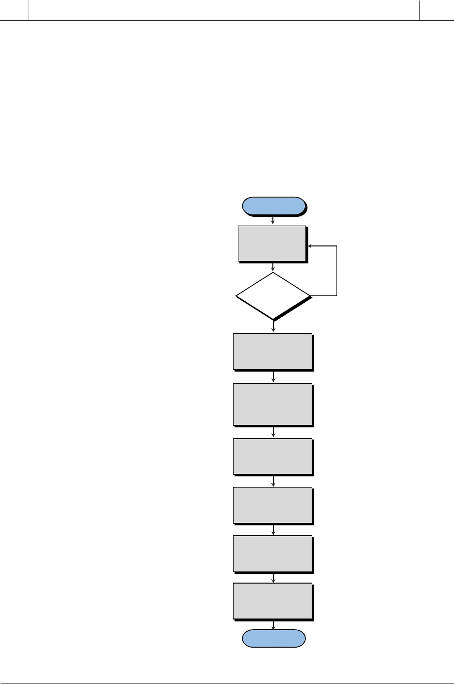
Figure 11-56 illustrates the flowchart for this system, while Tables 11-25, 11-
26, and 11-27 show the I/O address assignment, register assignment, and
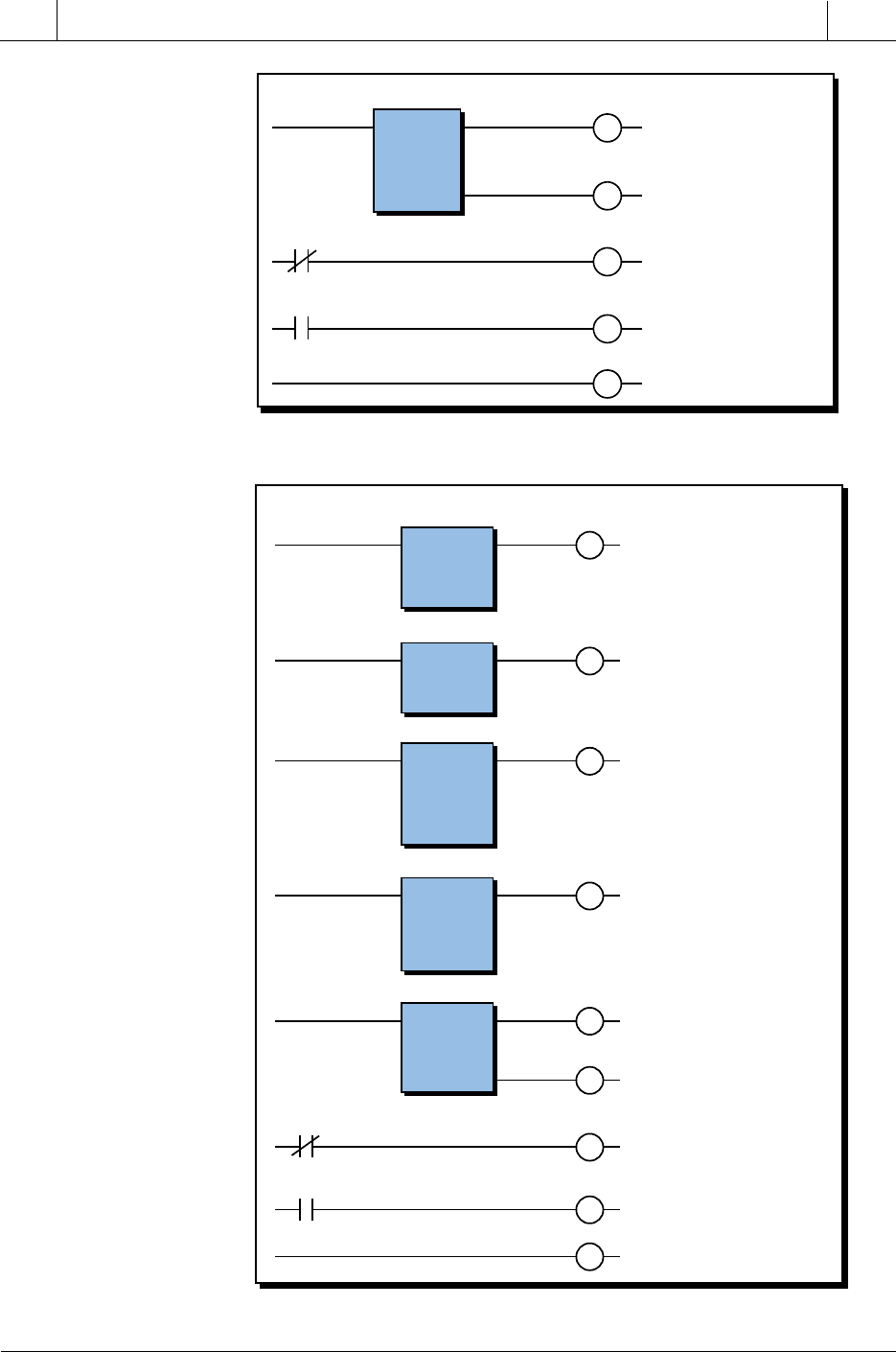
internal assignment, respectively. Figure 11-57 presents the PLC program
solution for this example.
Figure 11-56. Flowchart of the LVDT reading and virtual position calculations.
START
END
Yes
No
Read LVDT
analog input
continously.
GO SUB to ensure
that position is at
0 inches.
After V.P. is read,
start machine cycle.
Issue end of cycle.
Go back to V.P.
after end of
machine cycle.
If stop is pushed,
stop all machine
activity.
If reset is pushed,
stop activity and go
back to 0" position.
Once at 0 inches,
then go to V.P.
Read TWS and
convert to counts.
Is
Start PB1
ON?

500
SECTION
3
PLC
Programming
Industrial Text & Video Company 1-800-752-8398
www.industrialtext.com
CHAPTER
11
System Programming
and Implementation
Table 11-25. I/O address assignment.
Table 11-26. Register assignment.
Subroutines are used to implement the flowchart, to facilitate interlocking
and programming. Latch instructions enable the subroutines, allowing the
program to go to a subroutine until its operation has been performed. Once a
subroutine finishes its function, it sends an unlatch signal signifying the end
of the subroutine. This unlatch signal triggers the execution of the next
subroutine.
sserddAO/I
eludoM
epyT kcaR puorG lanimreT noitpircseD
tupnI 0 0 0 noitisoplautrivot—1BPtratS
0 0 1 )CN(enihcampots—2BPpotS
0 0 2 noitisop"0otteser—3BPteseR
0 0 3
retsigeR 0 1 0 fostigidowttnacifingistsoM
tupnI 0 1 1 noitisoplautriv(1lennahcSWT
hgih( 0 1 2 )stnioplamicedni
)etyb 0 1 3
0 1 4
0 1 5
0 1 6
0 1 7
retsigeR 0 2 0 fostigidowttnacifingistsaeL
tupnI 0 2 1 noitisoplautriv(1lennahcSWT
)etybwol( 0 2 2 )stnioplamicedni
0 2 3
0 2 4
0 2 5
0 2 6
0 2 7
tuptuO 0 3 0 dnammocdrawroF
0 3 1 dnammocesreveR
0 3 2
0 3 3
golanA 0 7 0 tupnigolanaTDVL1lennahC
tupnI 0 7 1 eraps2lennahC
0 7 2 eraps3lennahC
0 7 3 eraps4lennahC
retsigeR noitpircseD
0004 noitisoplautriv;DCBnieulavSWT
1004 noisrevnocretfayranibnieulavSWT
2004 )5904–(5904fonoitcartbuS
3004 )noitauqe(stnuocninoitisoplautriV
0014 stnuocnieulavgolanaTDVL

501
CHAPTER
11
System Programming
and Implementation
Industrial Text & Video Company 1-800-752-8398
www.industrialtext.com
SECTION
3
PLC
Programming
Table 11-27. Internal output assignment.
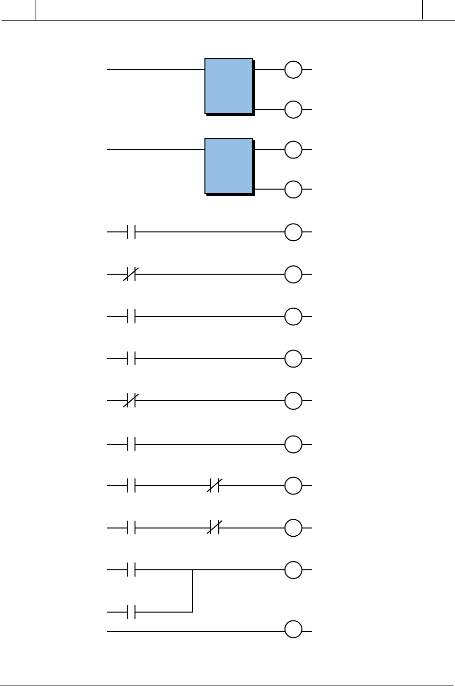
Figures 11-58, 11-59, and 11-60 present the subroutine codes. In Figure 11-
58 (check for 0-inch position), the compare instruction checks for the
LVDT count to be less than or equal to the compare constant –4090, rather
than strictly equal to the value –4095. If the instruction checked for the
value to be strictly equal to –4095, then fluctuations inherent in the
LVDT’s count output could cause the PLC to not latch this value. So, once
the LVDT passes –4090 counts, it latches this value and assumes that the
position is at 0 inches.
eciveD lanretnI noitpircseD
— 0001 dnammocenihcamtratS
— 1001 )daeRTDVL(dehsilbatsetupnigolanaTDVL
— 0011 enituorbusotogotelbanerofhctaL
— 0511 sehcni0htiwnoitisopTDVLerapmoC
— 1511 noitisop"0—dehcaernoitisoP
— 2511 bussihtmorfdnammocrotomesreverezigrenE
— 3511 dnuof"0noitisoptohs-enO
— 0021 )daeRSWT(enituorbusotogotelbaneothctaL
— 0521 )buSdaeRSWT(elbanekcolbSWTdaeR
— 1521 )lamiced(yranibotDCBmorftuptuotrevnoC
— 2521 elbane)noitauqeotgnidrocca(ylpitluM
— 3521 delbanetcartbuS
— 4521 delbaneerapmoC
— 5521 soP(NO4521—dnuof.P.V ≥ ).P.V
— 6521 bussihtmorfrotomdrawrofezigrenE
— 7521 dnuof.P.Vnoitisoptohs-enO
— 0031 .P.VotnruterotenituorbusotogotelbaneothctaL
— 0531 (.P.VhtiwTDVLerapmoC ≥ bus.P.VotnruteR—)
).P.V>soP(
— 1531 noitisoP ≥ ).P.VfodaehA(rotomesrever—.P.V
— 2531 (.P.VhtiwTDVLerapmoC ≤ ).P.V<soP()
— 3531 noitisoP ≤ ).P.VdniheB(rotomdrawrof—.P.V
— 4531 soPmorf.P.VdnuofhctaL ≥ fodaehaesreveR(.P.V
).P.V
— 5531 esrevermorf.P.VdnuoftohsenO
— 6531 soPmorf.P.VdnuofhctaL ≤ ).P.VdnihebdrawroF(.P.V
— 7531 drawrofmorf.P.VdnuoftohsenO
— 0631 bussihtmorfrotomesreveR
— 1631 bussihtmorfrotomdrawroF
— 2631 morf.P.VdnuoftohsenO ≤ morfro ≥ elcycretfa
— 0041 teserretfanoitisop"0rofbusotogotteserahctaL
— 0071 elcycenihcamotogothctaL
— 0571 elcycenihcambusoG
— 7771 )enoDelcyC(langiselcycfodnE

502
SECTION
3
PLC
Programming
Industrial Text & Video Company 1-800-752-8398
www.industrialtext.com
CHAPTER
11
System Programming
and Implementation
Figure 11-57. PLC implementation of the LVDT analog position reading example.
XFER IN
LVDT Read
1001
Rack 0
Slot 7
Reg 4100
Length 1
Start
000
Start Mach
1000
Start Mach
1000
Enable
GO SUB 1100
Start Mach
1000
Stop
001
Reset
002
Stop
001
Reset
002
Start machine–no stop, no reset.
Read analog position continu-
ously.
L
0" Found
1153
Enable Read TWS Sub
1200
L
Enable
GO SUB 1100
CMP LVDT = 0"
GO SUB 1150
0" Found
1153
1100
U
Stop
001
Reset
002
At VP Ready
1257
Cycle Ready
1700
L
Cycle Ready
1700
Cycle Machine
GO SUB 1750
Enable Read TWS Sub
1200
Read TWS Sub
GO SUB 1250
At V.P. Ready
1257
Deactivate
1200
U
After start, go to subroutine
and make sure at 0" to start.
Once at 0" position (1153 ON),
go to V.P.
Deactivate subroutine to look
for 0". System is stopped or
reset.
Deactivate read TWS sub to
look for V.P. because it is
found. System stop or reset.
Read TWS and look for V.P.
(sub 1250).
Once V.P. is achieved, start
cycle of the machine in sub-
routine 1750. The program of
subroutine 1750 (not included)
performs the machining task.
Deactivation of machine cycle
can also occur due to a stop or
reset command. Once cycle is
finished, the subroutine must
issue an OS 1777 to signify
the end of cycle from the sub-
routine. When it returns, the
machine cycle is deactivated.
Stop
001
Reset
002
Cycle Done
1777
Disable Cycle
1700
U
Stop
001
Reset
002
Found V.P. After Cycle
1362
Disable Sub
1300
U
Go Fwd 2
1361
Go Fwd 1
1256
FWD Motor
030
Go Rev 2
1360
Go Rev 1
1152
REV
031
FWD
030
REV
031
Cycle Done
1777
Back to V.P.
1300
L
Back to V.P.
1300
Sub Return to V.P.
GO SUB 1350
0" Found
1153 1400
U
Reset
002
Go to 0" after reset
1400
L
Go to 0" after reset
1400
CMP LVDT = 0"
GO SUB 1150
Once the end of cycle is
completed, return to V.P. for
next cycle. When V.P. is
achieved (1362 ON), proceed
to next cycle.
Found V.P. after cycle.
Disable subroutine to find the
V.P. after cycle. Can be
stopped because stop of
reset commands.
If reset is pushed, return to 0"
position and wait for start.
Disable looking for 0" posi-
tion after reset.
Forward Motor from com-
mands Go Fwd 1 (before cy-
cle) or Go Fwd 2 (after cycle).
Reverse motor.
503
CHAPTER
11
System Programming
and Implementation
Industrial Text & Video Company 1-800-752-8398
www.industrialtext.com
SECTION
3
PLC
Programming
Figure 11-59. Subroutine 1250 moves the part to the virtual position.
Figure 11-58. Subroutine 1150 brings moving part to 0" position.
XFER IN
Read TWS Sub
1250
Rack 0
Slot 1
Reg 4000
Length 1
V.P. Found
1255
At V.P. Ready
1257
OS
V.P. Found
1255
Go Fwd 1
1256
RET
Read TWS value in inches.
The format has two decimal
points (10
–2
).
BCD-BIN
BCD-BIN Done
1251
Reg 4000
Reg 4001
Length 1
Convert from BCD to binary
(decimal).
MUL
MUL Done
1252
Reg 4001
x
Reg K 4095
=
Reg 4002
Scale –3
Multiply decimal value
multiplier (x10
–2
because of
two decimals) with 409.5
(4095 x 10
–1
). Store in
register 4002 (counts).
Scale to 10
–3
due to both
multipliers.
SUB
SUB Done
1253
Reg 4002
–
Reg K 4095
=
Reg 4003
Subtract 4095 according to
the linearization equation.
CMP
1254
Reg 4100
≥
Reg 4003
V.P. Found
1255
Compare value of analog
input in counts with V.P. in
counts. If greater or equal,
indicate 1255 (ON).
If V.P. not found, start
motor. Move forward until
V.P. is reached.
V.P. reached. Proceed with
next operation.
≥
Ready for machine cycle.
CMP
Sub CMP LVDT = 0"
1150
Reg
4100
≤
Reg
K = –4090
0" Pos
1151
0" Pos
1151
Go Rev 1
1152
0" Pos
1151
0" Found
1153
RET
OS
Compare analog input
counts with counts for 0"
position.
Energize reverse motor
command if not at 0".
Once at 0", send signal to
main program to proceed.
≤
504
SECTION
3
PLC
Programming
Industrial Text & Video Company 1-800-752-8398
www.industrialtext.com
CHAPTER
11
System Programming
and Implementation
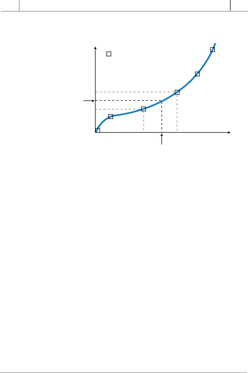
Figure 11-60. Subroutine 1350 returns the part to the virtual position at the end of cycle.
Behind V.P.
1353
≤
Ahead of V.P.
1351
≥
Return to V.P.
1350
Reg 4100
≥
Reg 4003
Ahead of V.P.
1351
Rev Ahead of PV
1354
Compare value of LVDT po-
sition with V.P. If greater or
equal, indicate 1351. If
1351 = ON, V.P. is not
found from a pos ≥ VP.
Compare value of LVDT
postion with V.P. If less or
equal, indicate 1353. If
1353 = ON, V.P. is not
found from a pos < V.P.
Found V.P. (latch signal) via
reversing motor command.
Issue a found command
(1355 ON).
OS stops reverse motor
command Go Rev 2 (1360).
Not back at V.P. from a
position greater than V.P.
Therefore, reverse motor.
Found V.P. (latch signal) via
forwarding motor command.
Issue a found command
(1357 ON).
Reverse motor until V.P. is
found.
OS stops forward motor
command Go Fwd 2 (1361).
Forward motor until V.P. is
found.
Issue command back to main
program that V.P. has been
reached after machine cycle.
Compare Done
1352
Reg 4100
≤
Reg 4001
L
Ahead of V.P.
1351
OS Found V.P. Rev
1355
OS
OS Found V.P. Rev
1355
Stop Rev Motor
1354
U
Behind V.P.
1353
Fwd Behind V.P.
1356
L
Behind V.P.
1353
OS Found V.P. Fwd
1357
OS
OS Found V.P. Fwd
1357
Stop Fwd Motor
1356
U
Rev Ahead of V.P.
1354
OS Fwd
1357
Go Rev 2
1360
Fwd Behind V.P.
1356
Go Fwd 2
1361
OS Found V.P. Rev
1355
Found V.P. After Cycle
1362
OS Found V.P. Fwd
1357
RET
OS Rev
1355

505
CHAPTER
11
System Programming
and Implementation
Industrial Text & Video Company 1-800-752-8398
www.industrialtext.com
SECTION
3
PLC
Programming
In Figure 11-59, scale multiplication allows the virtual position, which has
two decimal points (10
–2
) to be multiplied by the multiplication constant
(4095 × 10
–1
= 409.5); thus, the final scale is 10
–3
. This routine allows the
motor to move the part to the virtual position as specified by the LVDT. Once
the virtual position has been reached, the system is ready to start the machine
cycle (one-shot output 1257). The machine cycle subroutine will return an
end-of-cycle signal (output 1777) when finished, which disables the cycle
subroutine (see Figure 11-57).
When the end of cycle has occurred, the PLC will tell the motor to move either
forward or backward, depending on the moving part position at the end of
cycle. The interlocking performed by output rungs 1354 and 1355 (refer to
Figure 11-60) allow the motor to move in reverse if the part is farther than the
virtual position (current position > V.P.). Rungs 1356 and 1357 perform the
opposite function if the position of the part is closer than the virtual position
(current position < V.P.).
The one-shot circuits used in the LVDT application prevent the system from
moving the motor forward or backward until the part is at exactly the virtual
position in counts. Analog count signals may jump one or two counts in
either direction (up or down). This can result in instability, causing the
forward and reverse signals to clash. The logic that is employed in this
subroutine will detect, once the part crosses the virtual position (one-shot
outputs 1355 and 1357 in Figure 11-60), whether the part is coming from a
reverse motor or forward motor operation. Once the part is detected (i.e.,
when the one-shot is triggered), a minor jump in analog counts will not affect
the operation, since the program has already determined that the part has just
passed the virtual position. After the part stops at the virtual position, both the
forward and reverse motor commands from the subroutine are inhibited.
In some PLC applications, the analog input signal received does not have a
linear relationship with the signal being measured. That is, the ratio of
change in the measurement variable is not the same throughout the measure-
ment range. For example, a pressure transducer measuring hydraulic
pressure (see Figure 11-61) may not provide a signal that is a linear
representation of psi changes versus voltage changes (and therefore input
counts). Sometimes the system that is being controlled creates these
nonlinearities. The use of look-up tables and linear interpolation methods
based on premeasured values can circumvent nonlinearity problems. In
linear interpolation, the PLC stores known measured values in a table and
then refers to this table during the reading of every measurement (analog
counts) to determine the value of the variable (e.g., psi). It calculates this
value by interpolating between the known measured values of the variable
below and above the actual analog count reading. The more known values in
the table, the more accurate the interpolated values will be.
LINEAR INTERPOLATION OF NONLINEAR INPUTS
506
SECTION
3
PLC
Programming
Industrial Text & Video Company 1-800-752-8398
www.industrialtext.com
CHAPTER
11
System Programming
and Implementation
To provide an example of this type of application, we will use a system with
a pressure transducer that provides a 0 to +10 VDC output. The range of the
pressure measurement is from 0 to 1000 psi. Measurement tests have shown
that the relationship associated with the transducer’s measurement is nonlin-
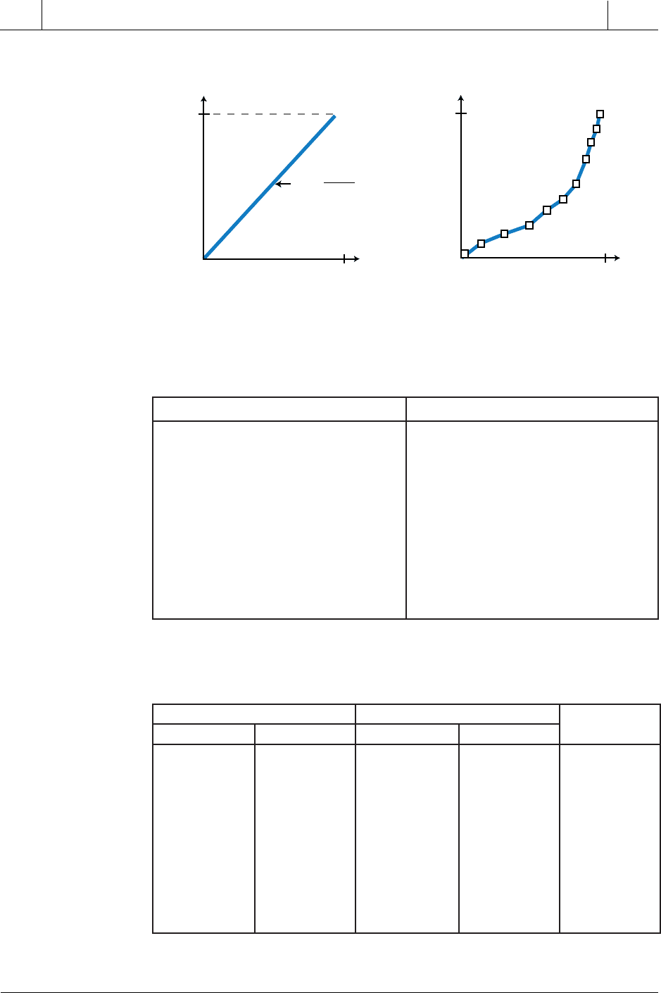
ear. Figure 11-62 illustrates the difference between a linear curve and the
actual nonlinear measurements. The analog input module transforms the 0 to
10 VDC signal into counts ranging from 0 to +4095. Table 11-28 shows the
test counts for different psi pressure values.
Let’s assume that the control algorithm requires the input measurement to
be converted to engineering units (in this case, psi). Since we cannot perform
this conversion based on a linear equation, we must obtain the psi values by
estimating a pressure according to an input count reading. The PLC
performs this linear interpolation by looking through tables (groups of
contiguous registers) for a psi value equivalent to the counts. The two tables
the PLC uses are the psi measurement table and its corresponding count value
table. The psi table starts at register 3100, and the count table starts at register
3000. Table 11-29 shows these two tables, along with the corresponding
pointer values. The pointer (register 4000) points at a register in the table
according to a specified offset (table-to-register instruction). For instance, if
the pointer value is 3 (reg 4000 = 3), then it points to psi register 3102 and
count register 3002. The contents of the pointer register are in decimal, while
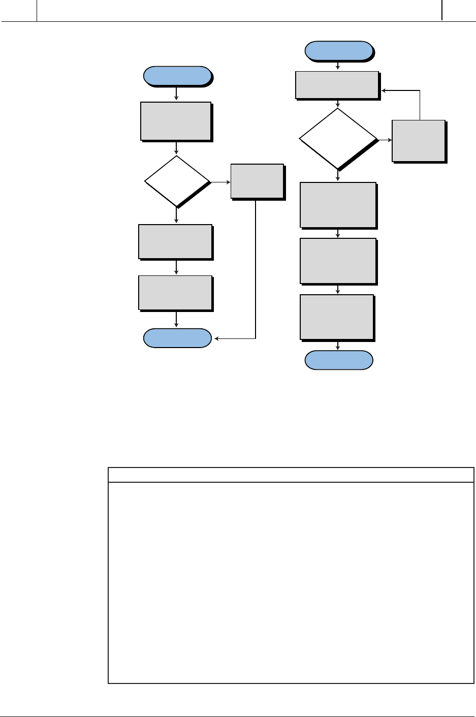
the other registers are in octal. Figure 11-63 shows the flowchart for the look-
up and interpolation procedures.
Figure 11-61. Nonlinear input signals from a pressure transducer.
Pressure
Variable
(psi)
Actual known value measurements
psi B
psi A
Interpolated
value of psi
Analog
Counts
Count A Count B
Measurement
507
CHAPTER
11
System Programming
and Implementation
Industrial Text & Video Company 1-800-752-8398
www.industrialtext.com
SECTION
3
PLC
Programming
Figure 11-62. (a) Linear behavior and (b) actual nonlinear measurements.
Table 11-28. Sample psi measurements and corresponding counts.
tnemerusaeMisp stnuoCtupnIgolanA
0 0
05 006
001 0021
051 0051
002 0591
052 0822
003 0092
004 0033
006 0073
008 0283
0001 0904
Table 11-29. Look-up tables for psi and count values.
isp elbaT stnuoC elbaT retnioP
retsigeR isp retsigeR stnuoC 0004geR
0013 0 0003 0 1
1013 05 1003 006 2
2013 001 2003 0021 3
3013 051 3003 0051 4
4013 002 4003 0591 5
5013 052 5003 0822 6
6013 003 6003 0092 7
7013 004 7003 0033 8
0113 006 0103 0073 9
1113 008 1103 0283 01
2113 0001 2103 0904 11
0 psi
1000 psi
4095
Counts
Counts
0
Linear
0 psi
1000 psi
40950
Nonlinear
(a) (b)
Y
psi
=
X
Counts
1000
4095
psi
psi
508
SECTION
3
PLC
Programming
Industrial Text & Video Company 1-800-752-8398
www.industrialtext.com
CHAPTER
11
System Programming
and Implementation
Figure 11-63. (a) Main program look-up procedure and (b) interpolation subroutine.
Table 11-30 shows the register assignment table for this example, and Table
11-31 shows the internal output assignment. The analog input module, with
address 070, is the only real input.
Table 11-30. Register assignment.
START
END
Yes
No
Read
analog input
counts
Go to subroutine
to look-up table
and interpolate
Set pointer P to
second table
location
Is
input count
= 0 ?
Then psi is
equal to 0
START
Return
Yes
No
Move value from
table to register
Save pointer (P)
position and
decrement for low
value (P–1)
Move table to
registers for P and
P–1 index for psi
and counts
Perform math
interpolation and
store in result
register
Is
table count
value > input
counts?
Increment
pointer
P for next
table value
(b)(a)
retsigeR noitpircseD
0003 )2103–0003gerstnuoc(egarotselbatpu-kooL
0013 )2113–0013gerisp(egarotselbatpukooL
0004 1–PretnioP
0504 PretnioP
0014 )erusserp(stnuoctupnigolanA
0514 )noitalopretniretfadetupmoc(retsigertluserisp
0044 RretsigerispwoL
wol-isp
0544 RretsigerisphgiH
hgih-isp
0054 retsigertnuocwoLR
wol-stnuoc
0554 RretsigertnuochgiH
hgih-stnuoc
0064 )tcartbus(retsigeryraropmeT
1064 )tcartbus(retsigeryraropmeT
2064 )ylpitlum(retsigeryraropmeT
3064 )ylpitlum(retsigeryraropmeT
4064 )edivid(retsigeryraropmeT
