Bryan L. Programmable controllers. Theory and implementation
Подождите немного. Документ загружается.

469
CHAPTER
11
System Programming
and Implementation
Industrial Text & Video Company 1-800-752-8398
www.industrialtext.com
SECTION
3
PLC
Programming
SIMPLE START/STOP MOTOR CIRCUIT
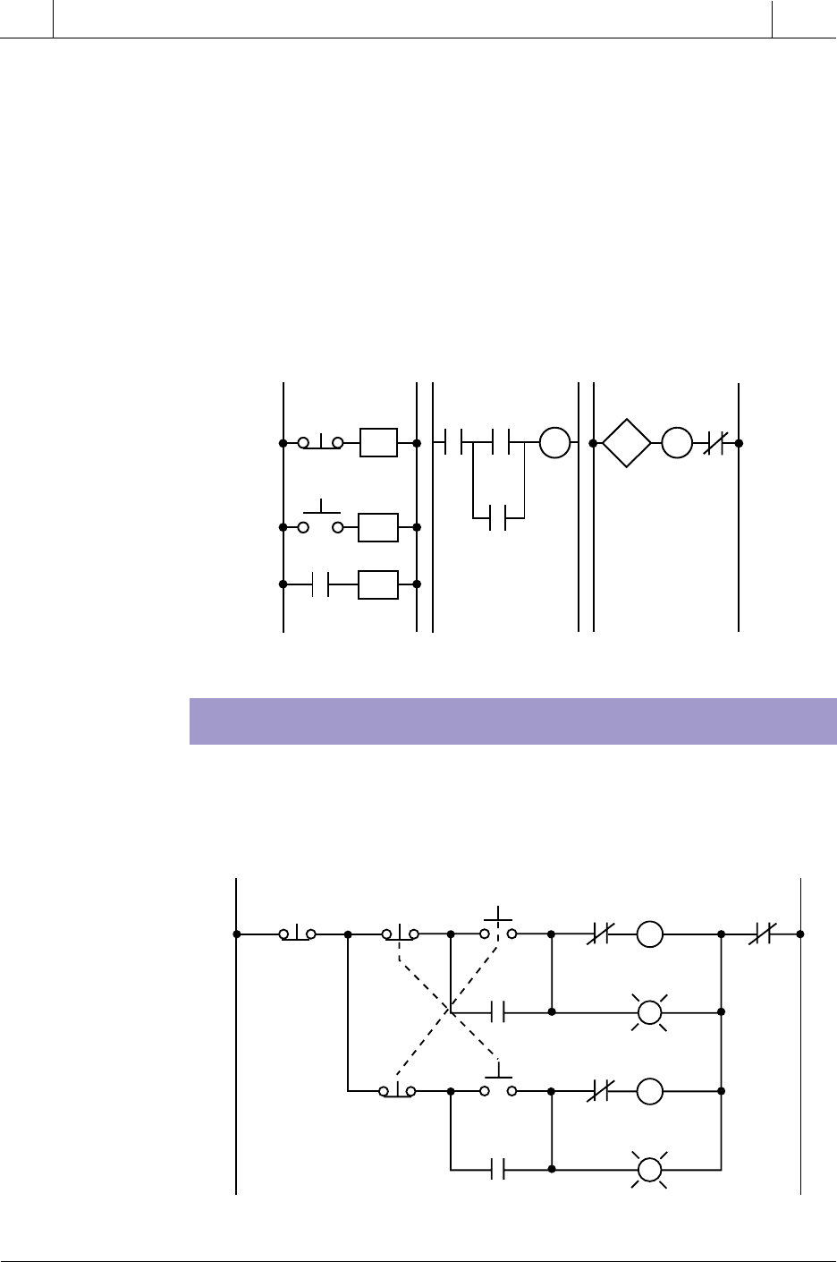
Figure 11-24. PLC implementation of the circuit in Figure 11-23.
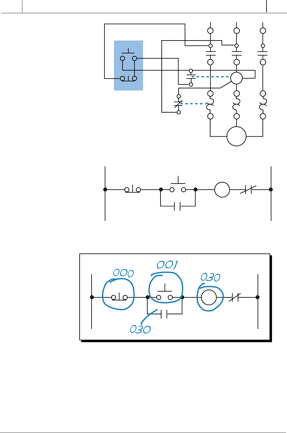
Figure 11-25 shows the wiring diagram for a three-phase motor and its
corresponding three-wire control circuit, where the auxiliary contacts of the
starter seal the start push button. To convert this circuit into a PLC program,
first determine which control devices will be part of the PLC I/O system; these
are the circled items in Figure 11-26. In this circuit, the start and stop push
buttons (inputs) and the starter coil (output) will be part of the PLC system.
The starter coil’s auxiliary contacts will not be part of the system because an
internal will be used to seal the coil, resulting in less wiring and fewer
L1 L1 L2L2
PB1
PS1
PB1
000
TMR Trap
1000
PS1
001
TMR Trap
1000
030
000
001
PS2
005
TS1
FS1
002
TS1
003
SOL1
030
TMR1
1001
SOL1
030
CR3
1003
003
FS1
TMR Trap
1000
TMR1
1001
TMR2
1002
002
TMR2
1002
PS2
005
CR3
1003
SOL3
032
TMR1
1001
SOL1
030
LS1
004
LS1
TMR1
1001
SOL1
030
LS1
004
SOL2
031
004
TMR
PR 4000
30
AR 4001
TB = 0.1
TMR
PR 4002
20
AR 4003
TB = 0.1
SOL1
031
SOL2
032
SOL3
470
SECTION
3
PLC
Programming
Industrial Text & Video Company 1-800-752-8398
www.industrialtext.com
CHAPTER
11
System Programming
and Implementation
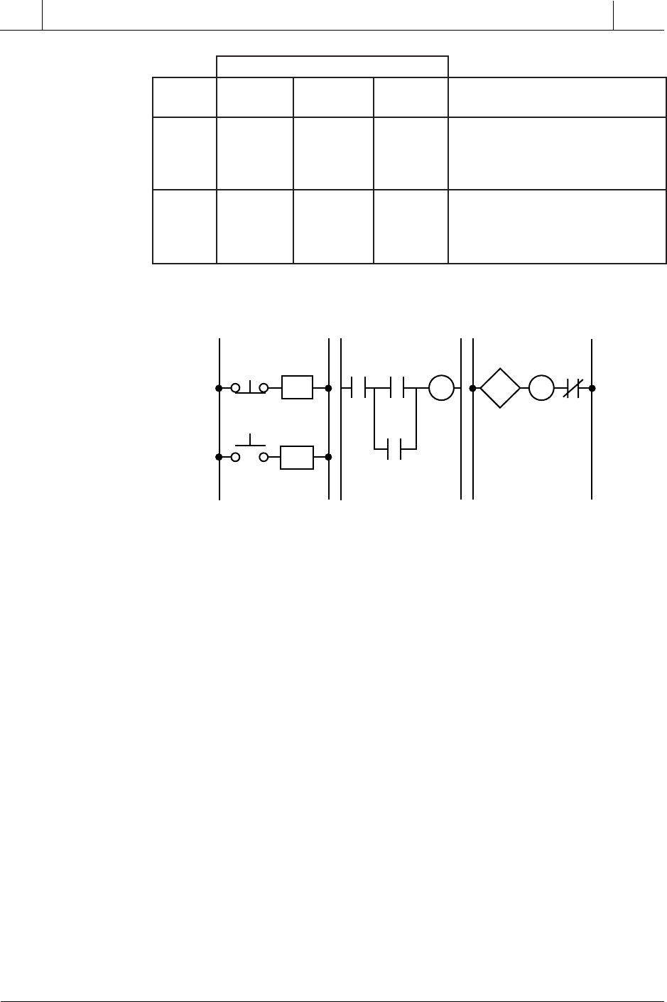
connections. Table 11-11 shows the I/O address assignment, which uses the
same addressing scheme as the circuit diagram (i.e., inputs: addresses 000
and 001, output: address 030).
To program the PLC, the devices must be programmed in the same logic
sequence as they are in the hardwired circuit (see Figure 11-27). Therefore,
the stop push button will be programmed as an examine-ON instruction
Figure 11-25. (a) Wiring diagram and (b) relay control circuit for a three-phase motor.
Figure 11-26. Real inputs and outputs to the PLC.
(a)
(b)
L1 L2
Start
Stop
M
OL
M
23
Motor
3
2
T1 T2 T3
L1 L2 L3
OL
M
Power
Start
Stop
M
(a)
Push Button
Station
(three-wire control)
L1 L2
Start
Stop
M
OL
M
23
471
CHAPTER
11
System Programming
and Implementation
Industrial Text & Video Company 1-800-752-8398
www.industrialtext.com
SECTION
3
PLC
Programming
Table 11-11. I/O address assignment.
Figure 11-27. PLC implementation of the circuit in Figure 11-25.
(a normally open PLC contact) in series with the start push button, which is
also programmed as an examine-ON instruction. This circuit will drive output
030, which controls the starter. If the start push button is pressed, output 030
will turn ON, sealing the start push button and turning the motor ON through
the starter. If the stop push button is pressed, the motor will turn OFF. Note
that the stop push button is wired as normally closed to the input module. Also,
the starter coil’s overloads are wired in series with the coil.
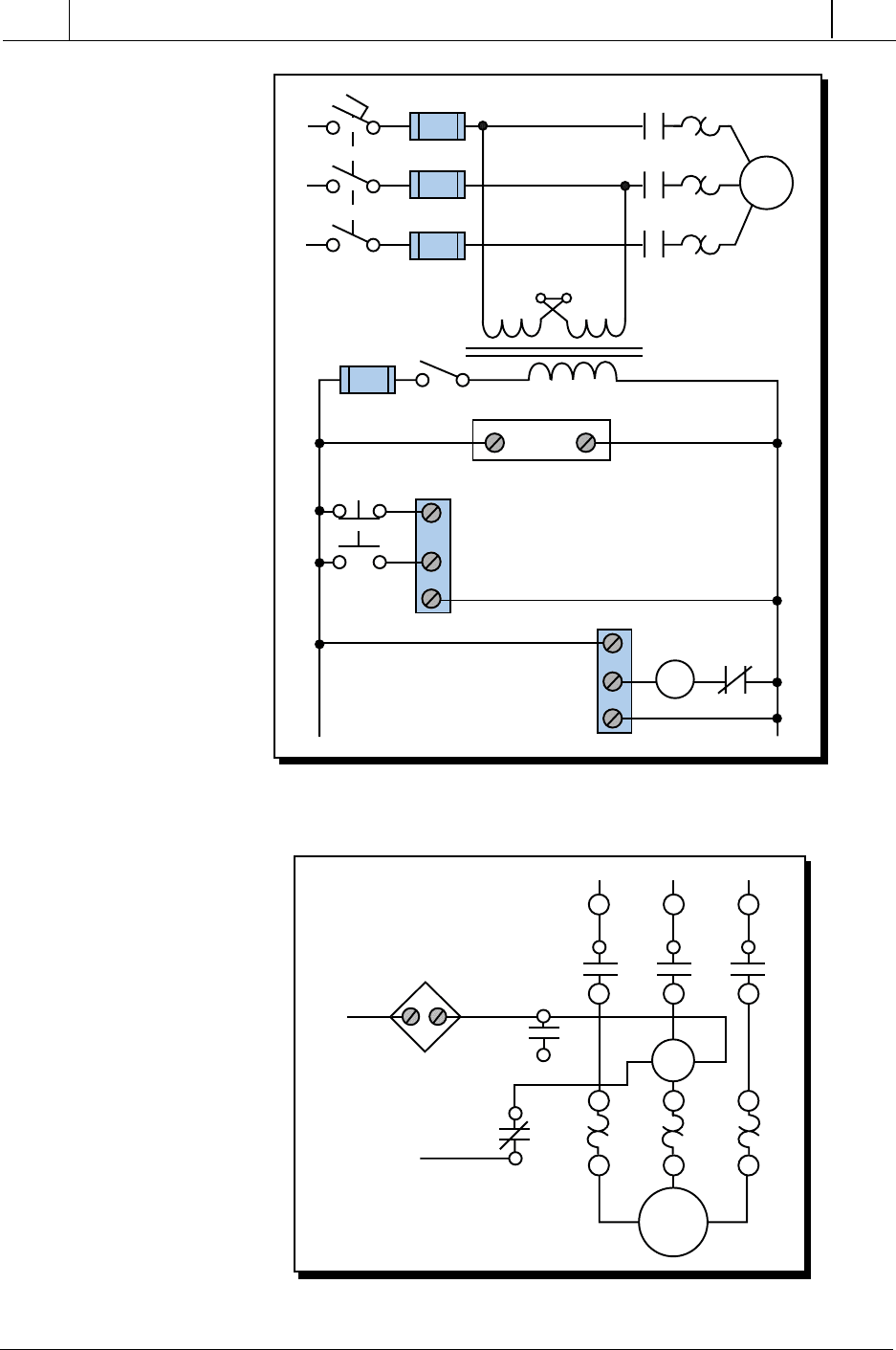
In a PLC wiring diagram, the PLC is connected to power lines L1 and L2
(see Figure 11-28). The field inputs are connected to L1 on one side and to
the module on the other. The common, or return, connection from the input
module goes to L2. The output module receives its power for switching the
load from L1. Output terminal 030 is connected in series with the starter coil
and its overloads, which go to L2. The output module also directly connects
to L2 for proper operation. Note that, in the motor control circuit’s wiring
diagram (see Figure 11-29), the PLC output module is wired directly to the
starter coil.
Although the three-phase motor has a three-wire control circuit, its corre-
sponding PLC control circuit has only two wires. This two-wire configuration
is similar to a three-wire configuration because it provides low-voltage
release; however, it does not provide low-voltage protection. Referring to
sserddAO/I
eludoM
epyT kcaR puorG lanimreT noitpircseD
tupnI 0 0 0 )CN(BPpotS
0 0 1 BPtratS
0 0 2 —
0 0 3 —
tuptuO
0 3 0 1MrotoM
0 3 1 —
0 3 2 —
0 3 3 —
L2
L1 L1
L2
001
000
Start
Stop
MOL
M
030
Start
001
Stop
000
M
030
030
472
SECTION
3
PLC
Programming
Industrial Text & Video Company 1-800-752-8398
www.industrialtext.com
CHAPTER
11
System Programming
and Implementation
Figure 11-28. PLC wiring diagram of a three-phase motor.
Figure 11-29. Motor control circuit’s wiring diagram.
Motor
3
2
T1 T2 T3
L1 L2 L3
M
OL
PLC
Output
030
From
L1
To L2
PLC
M
L1
000
001
L2
Stop
Start
Inputs
L1
L2
L3
M
OL
F
Outputs 030
Common
Common
Power
473
CHAPTER
11
System Programming
and Implementation
Industrial Text & Video Company 1-800-752-8398
www.industrialtext.com
SECTION
3
PLC
Programming
Figure 11-29, the starter’s seal-in contacts (labeled as 3—| |—2) are not used
and are shown as unconnected. If the motor is running and the overloads
open, the motor will stop, but the circuit will still be ON. Once the overloads
cool off and the overload contacts close, the motor will start again immedi-
ately. Depending on the application, this situation may not be desirable. For
example, someone may be troubleshooting the motor stoppage and the motor
may suddenly restart. Making the auxiliary contact an input and using its
address to seal the start push button can avoid this situation by making the
two-wire circuit act as a three-wire circuit (see Figure 11-30). In this
configuration, if the overloads open while the motor is running, the coil will
turn off and their auxiliary contacts will break the circuit in the PLC.
Figure 11-30. Two-wire circuit configured as a three-wire circuit.
FORWARD/REVERSE MOTOR INTERLOCKING
Figure 11-31. Hardwired forward/reverse motor circuit.
L2
L1 L1
L2
001
000
Start
M
Stop
MOL
002
M
002
Start
001
Stop
000
M
030
030
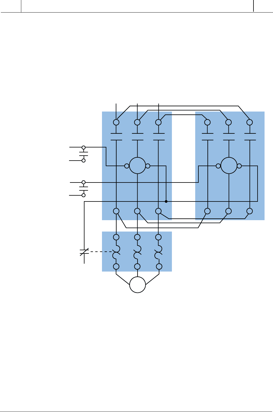
Figure 11-31 illustrates a hardwired forward/reverse motor circuit with
electrical and push button interlockings. Figure 11-32 shows the simplified
wiring diagram for this motor. The PLC implementation of this circuit
L1 L2
Stop Rev R M1
For PL1
M1
All OLs
For
F
FM2
Rev PL2
M2
R
474
SECTION
3
PLC
Programming
Industrial Text & Video Company 1-800-752-8398
www.industrialtext.com
CHAPTER
11
System Programming
and Implementation
should include the use of the overload contacts to monitor the occurrence of
an overload condition. The auxiliary starter contacts (M1 and M2) are not
required in the PLC program because the sealing circuits can be programmed
using the internal contacts from the motor outputs. Low-voltage protection
can be implemented using the overload contact input so that, if an overload
occurs, the motor circuit will turn off. However, after the overload condition
passes, the operator must push the forward or reverse push button again to
restart the motor.
Figure 11-32. Forward/reverse motor wiring diagram.
For simplicity, the PLC implementation of the circuit in Figure 11-31
includes all of the elements in the hardwired diagram, even though the
additional starter contacts (normally closed R and F in the hardwired circuit)
are not required, since the push button interlocking accomplishes the same
task. In the hardwired circuit, this redundant interlock is performed as a
backup interlocking procedure.
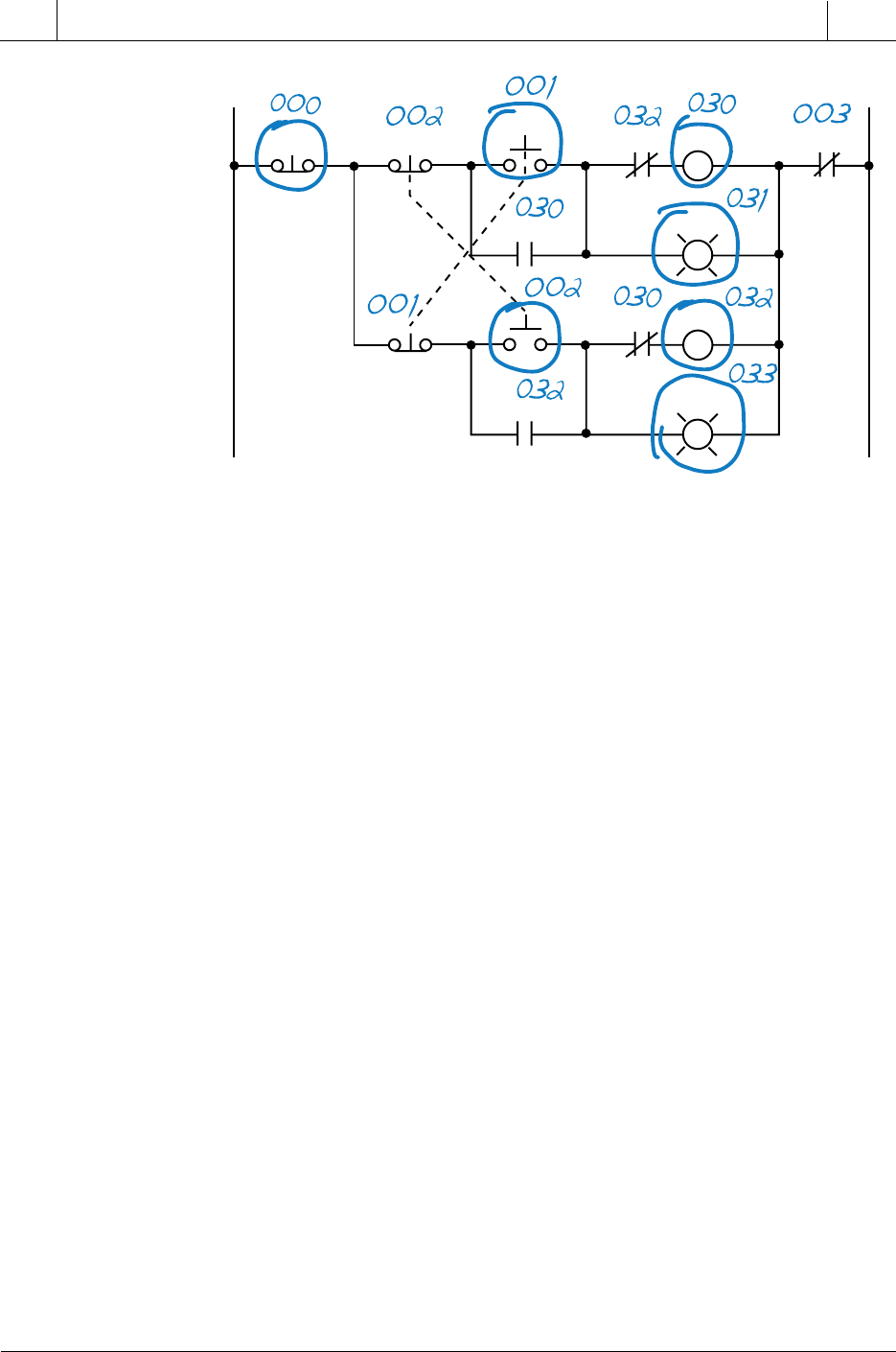
Figure 11-33 shows the field devices that will be connected to the PLC. The
stop push button has address 000, while the normally open sides of the
forward and reverse push buttons have addresses 001 and 002, respectively.
The overload contacts are connected to the input module at address 003. The
L1 L2 L3
M
F
R
123 123
T1 T3
T2
F
3
2
R
3
2
OL
475
CHAPTER
11
System Programming
and Implementation
Industrial Text & Video Company 1-800-752-8398
www.industrialtext.com
SECTION
3
PLC
Programming
output devices—the forward and reverse starters and their respective inter-
locking auxiliary contacts—have addresses 030 and 032. The forward and
reverse pilot light indicators have address 031 and 033, respectively. Addi-
tionally, the overload light indicators have addresses 034 and 035, indicat-
ing that the overload condition occurred during either forward or reverse
motor operation. The addresses for the auxiliary contact interlocking using
the R and F contacts are the output addresses of the forward and reverse
starters (030 and 032). The ladder circuit that latches the overload condition
(forward or reverse) must be programmed before the circuits that drive the
forward and reverse starters as we will explain shortly. Otherwise, the PLC
program will never recognize the overload signal because the starter will be
turned off in the circuit during the same scan when the overload occurs. If the
latching circuit is after the motor starter circuit, the latch will never occur
because the starter contacts will be open and continuity will not exist.
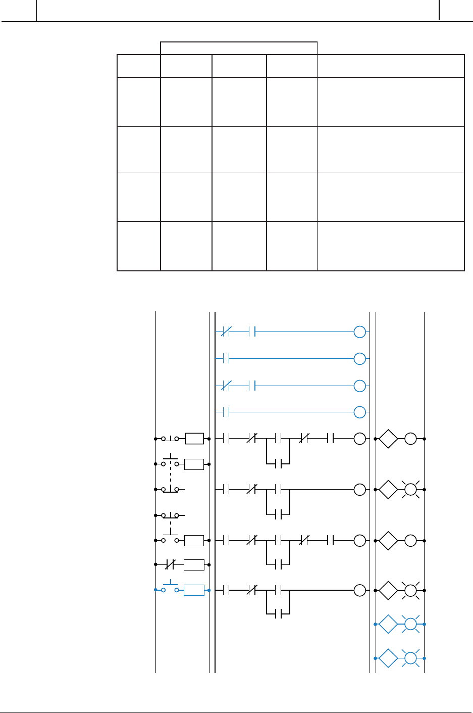
Table 11-12 shows the real I/O address assignment for this circuit. Figure
11-34 shows the PLC implementation, which follows the same logic as the
hardwired circuit and adds additional overload contact interlockings. Note
that the motor circuit also uses the overload input, which will shut down the
motor. The normally closed overload contacts are programmed as normally
open in the logic driving the motor starter outputs. The forward and reverse
motor commands will operate normally if no overload condition exists
because the overload contacts will provide continuity. However, if an
overload occurs, the contacts in the PLC program will open and the motor
circuit will turn OFF. The overload indicator pilot lights (OL Fault Fwd and
OL Fault Rev) use latch/unlatch instructions to latch whether the overload
occurred in the forward or reverse operation. Again, the latching occurs
before the forward and reverse motor starter circuits, which will turn off due
Figure 11-33. Real inputs and outputs to the PLC.
L1 L2
Stop Rev R M1
For PL1
M1
All OLs
For
F
FM2
Rev PL2
M2
R
476
SECTION
3
PLC
Programming
Industrial Text & Video Company 1-800-752-8398
www.industrialtext.com
CHAPTER
11
System Programming
and Implementation
Table 11-12. I/O address assignment.
Figure 11-34. PLC implementation of the circuit in Figure 11-31.
sserddAO/I
eludoM
epyT kcaR puorG lanimreT noitpircseD
tupnI 0 0 0 )CNderiw(BPpotS
0 0 1 )ONderiw(BPdrawroF
0 0 2 )ONderiw(BPesreveR
0 0 3 stcatnocdaolrevO
tupnI 0 0 4 BPteseR/LOegdelwonkcA
• • •
• • •
• • •
tuptuO 0 3 0 )DWF(1MretratsrotoM
0 3 1 1LPdrawroF
0 3 2 )VER(2MretratsrotoM
0 3 3 2LPesreveR
tuptuO
0 3 4 DWFnoitidnocdaolrevO
0 3 5 VERnoitidnocdaolrevO
0 3 6 —
0 3 7 —
L2L1L2
L1
030
002
000
Reverse
Stop
M
031
Fwd PL1
003
OL
M1
030
Rev
002
M1
030
Stop
000
Fwd
001
M2
032
OL
003
032
M2
032
Rev
002
M1
030
Stop
000
Fwd
001
M2
032
OL
003
M1
030
Rev
002
PL1
031
Stop
000
Fwd
001
M1
030
OL Fwd
034
OL
003
001
Forward
034
R
M2
033
M2
032
Rev
002
Stop
000
Fwd
001
PL
033
004
ACK OL Reset
Rev PL2
L
OL Fwd
034
U
M2
032
OL Rev
035
OL
003
035
L
OL Rev
035
U
OL Fault
Fwd
OL Fault
Rev
ACK OL
004
ACK OL
004
477
CHAPTER
11
System Programming
and Implementation
Industrial Text & Video Company 1-800-752-8398
www.industrialtext.com
SECTION
3
PLC
Programming
to the overload. An additional normally open acknowledge overload reset
push button, which is connected to the input module, allows the operator to
reset the overload indicators. Thus, the overload indicators will remain
latched, even if the physical overloads cool off and return to their normally
closed states, until the operator acknowledges the condition and resets it.
Figure 11-35 illustrates the motor wiring diagram of the forward/reverse
motor circuit and the output connections from the PLC. Note that the
auxiliary contacts M1 and M2 are not connected. In this wiring diagram,
both the forward and reverse coils have their returns connected to L2 and not
to the overload contacts. The overload contacts are connected to L1 on one
side and to the PLC’s input module on the other (input 003). In the event of
an overload, both motor starter output coils will be dropped from the circuit
because the PLC’s output to both starters will be OFF.
Figure 11-35. Forward/reverse motor wiring diagram.
REDUCED-VOLTAGE-START MOTOR CONTROL
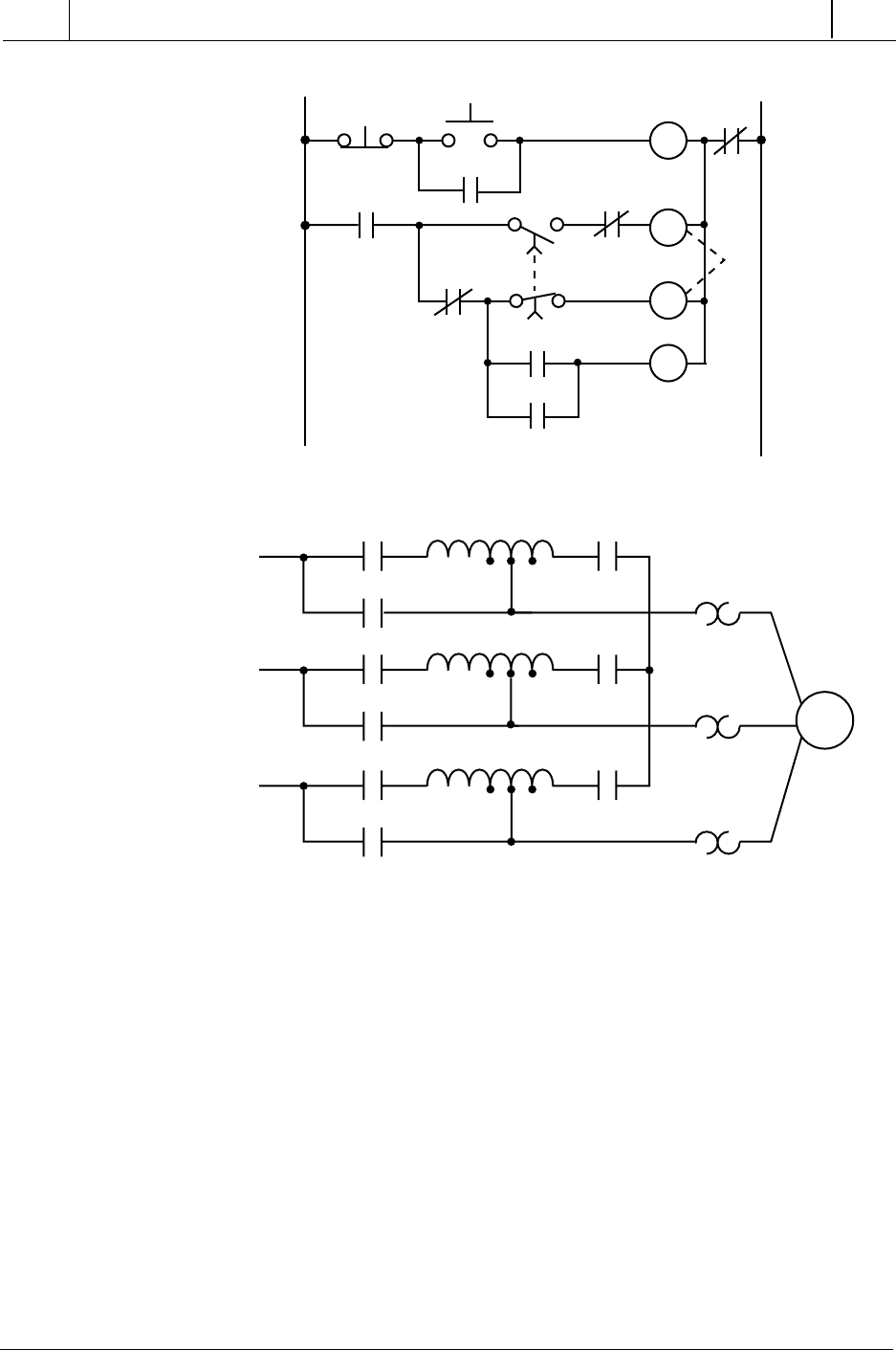
Figure 11-36 illustrates the control circuit and wiring diagram of a 65%
tapped, autotransformer, reduced-voltage-start motor control circuit. This
reduced-voltage start minimizes the inrush current at the start of the motor
(locked-rotor current) to 42% of that at full speed. In this example, the timer
must be set to 5.3 seconds. Also, the instantaneous contacts from the timer in
lines 2 and 3 must be trapped.
L1 L2 L3
L1
To PLC
Input 003
L1
L2
L1
F
M
FWD
REV
R
OL
3
2
M1
3
2
M2
478
SECTION
3
PLC
Programming
Industrial Text & Video Company 1-800-752-8398
www.industrialtext.com
CHAPTER
11
System Programming
and Implementation
Figure 11-36. (a) Hardwired relay circuit and (b) wiring diagram of a reduced-voltage-
start motor.
Figure 11-37 illustrates the hardwired circuit with the real inputs and outputs
circled. The devices that are not circled are implemented inside the PLC
through the programming of internal instructions. Tables 11-13, 11-14, and
11-15 show the I/O assignment, internal assignment, and register assignment,
respectively. Figure 11-38 illustrates the PLC implementation of the reduced-
voltage-start circuit. The first line of the PLC program traps the timer with
internal output 1000. Contacts from this internal replace the instantaneous
timer contacts specified in the hardwired control circuit. This PLC circuit
implementation does not provide low-voltage protection, since the interlock-
ing does not use the physical inputs of M1, S1, and S2. If low-voltage
protection is required, then the starter’s auxiliary contacts or the overload
contacts can be programmed as described in the previous examples. If the
auxiliary contacts or the overloads are used as inputs, they must be pro-
Stop
Start
OL
L1 L2
TR1
TR1
S1
S1
TR1
TR1
TR1
S2
S2
S1
M1
M1
T1
T2
T3
M
S1
S2
M1
S1
S2
M1
S1
S2
M1
L1
L2
L3
65%
1
2
3
4
5
6
(a)
(b)
