Blum W., Riegler W., Rolandi L. Particle Detection with Drift Chambers
Подождите немного. Документ загружается.

382 11 Existing Drift Chambers – An Overview
Fig. 11.17 Mark II drift cell
with electron trajectories
The small cell of the SLD drift chamber (Fig. 11.18) is designed to create a better
separation between the amplification region and the drift region by displacing the
field wires from their position between the sense wires to a position surrounding
them. This is done to create a uniform drift region for the slow gas employed. Here
the good diffusion properties of carbon dioxide have been combined with its low
drift velocity at high electric fields. Thus the Lorentz angle is kept near 6
◦
at the
field of 0.6 T. On the other hand, this imposes severe requirements on the electric
field uniformity, since the drift velocity under these conditions is proportional to the
electric field (‘unsaturated gas’). There are 640 drift cells in the detector. A very
favourable point-measuring accuracy of 55 μm was obtained with the prototype.
This requires that the wire displacements caused by mechanical inaccuracy, gravity,
and electrostatic forces as well as by the stereo arrangement are fully controlled to
this precision.
Fig. 11.18 SLD drift cell with
electron drift lines
11.5 Large Cylindrical Drift Chambers of Type 2 383
Fig. 11.19 A drift cell of the CDF central tracking chamber, with electron drift lines
The drift cells of the central tracking chamber of the CDF detector (Fig. 11.19)
are inclined by 45
◦
with respect to the radial direction in order to take the Lorentz
angle at the employed magnetic field of 1.5 T into account. This solution also offers
advantages for triggering and for pattern recognition. The arrangement of the drift
cells, of which there are 660, in the end plate can be seen in Fig. 11.20. The cells
are divided radially into nine superlayers which alternate between wires in the axial
direction and wires at a ±3
◦
stereo angle. Tilted drift cells are also employed for
the drift chambers of the H1 and ZEUS experiments at the HERA e-p collider.
Fig. 11.20 The end plate of
the CDF central tracking
chamber with its drift cells,
which are inclined with
respect to the radial direction
384 11 Existing Drift Chambers – An Overview
11.5.4 The UA1 Central Drift Chamber
The detector fills a cylinder, 6 m long and 2.2 m in diameter, which contains the
collider-beam pipe on its axis. Equally horizontal, but at right angles to the beam, is
the magnetic field of 0.7 T (see Fig. 11.21). Along its length, the cylinder is divided
into three cylindrical sections, each 2 m long: the central section and the two forward
ones. The wires are all parallel to the magnetic field and organized in planes accord-
ing to the following scheme: the anode planes have alternating sense (35 μmdiam)
and field (100 μm diam) wires every 5 mm; the cathode planes with 120−μmwires,
also every 5 mm, are parallel to the anode planes, leaving drift spaces of 18 cm be-
tween them. A peculiarity of the UA1 detector is the orientation of these planes –
they are vertical in the central cylinder part and horizontal in the forward parts. This
arrangement is a consequence of the horizontal magnetic field; the solution opti-
mizes the momentum-measuring accuracy, the track curvature being measured by
the drift time. The charge-division technique is used for the coordinate along the
wire direction. Filled with a gas mixture of 40% Ar and 60% C
4
H
10
at ambient
pressure, the drifting electrons reach a velocity of 5.3 cm/μs under a Lorentz an-
gle of 23
◦
in their drift field of 1500 V/cm. The total number of wires is 22 800, of
which 6110 are sense wires. A stiff vertical track is measured on 100 points and a
stiff track near the forward directions on up to 180 points.
Fig. 11.21 Geometry of the
UA1 central detector
11.5 Large Cylindrical Drift Chambers of Type 2 385
Performance figures were measured in the experiment as follows [NOR 90]: The
average point-measuring accuracy in the direction of the drift amounted to 350 μm.
The relative accuracy of momentum measurement, which depends very much on
the track orientation, was typically
δ
p/p =(0.01 GeV/c
−1
)p for isolated tracks in
a favourable direction (obviously, the curvature of tracks that emanate from the in-
teraction region under a polar angle of 90
◦
and parallel to the magnetic field cannot
be measured.) The electronic two-track resolution limit on a wire was about 5 mm.
The coordinate measurement accuracy along the wires was 3.5% r.m.s. of the wire
length after the gain reduction by a factor of three that was necessary when the de-
tector had to work in the high-luminosity environment; before this change, 2% had
been reached. These numbers illustrate the conflicting requirements of having the
smallest possible space charge in the drift region (small wire amplification) and the
best possible charge-division accuracy (large amplification) at the same time.
Ionization measurements of tracks in this complex detector were limited in accu-
racy and were not employed for particle identification.
In Fig. 11.22 we reproduce an event as reconstructed by the computer; the high
number of measured points along each track make a clear picture even for the com-
plicated events created in high-energy hadron collisions – in fact this picture is
famous because it contains the first Z
0
particle ever observed. The two arrows mark
the electron and the positron into which it decays.
11.5.5 The ATLAS Muon Drift Chambers (MDT)
The ATLAS experiment at the Large Hadron Collider (LHC) will investigate
pp-collisions with a total energy of 14 TeV; muons with transverse momenta up
to 1 TeV/c will be detected and measured in the muon spectrometer [ATL 97]. The
purpose of the muon drift chambers is to determine the momenta of the muons as
accurately as possible.
The ATLAS magnet produces a toroidal field in air (field lines going around
the beam) which offers a high bending power at much reduced Coulomb scattering
Fig. 11.22 Computer-reconstructed event in the UA1 central detector – the first Z
0
particle ever
observed is seen to decay into an e
+
and an e
−
. Only one in two wire signals is displayed
386 11 Existing Drift Chambers – An Overview
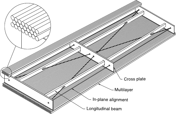
Fig. 11.23 ATLAS muon drift chamber, consisting of a pair of threefold tube layers, separated by
a spacer frame
because there is no iron yoke. The chambers consist of simple aluminium drift tubes
with a diameter of 3 cm, carrying a central wire. (The theoretical work as well as the
practical measurements that were done in order to find the best operating conditions
for these tubes were published in a series of papers in 2000 [RIE 00]). They are
mounted to form chambers as shown in Fig. 11.23; almost all chambers consist of
a pair of threefold plane layers of parallel tubes, the triple layers being separated
by a spacer. This is the basic unit, mostly 1 to 2 m wide and up to 6 m long in the
direction of the tubes. There are 1194 of them, covering a total surface of 5500 m
2
.
As the coordinate measurement of the drift tubes is perpendicular to the wires, the
chambers are oriented with the wires essentially following the magnetic field lines.
In the ‘barrel’, the chambers are arranged in three cylindrical concentric layers so
that a stiff particle track from the interaction point is measured in all three layers for
optimum momentum resolution (see Fig. 11.24). The vertical detectors in the ‘end-
caps’ measure tracks in the more forward or backward directions in a similar way.
It should be noted that the muon drift chambers can only determine one coordinate,
the one that is useful for the momentum measurement. The azimuthal coordinate of
a track is measured in other detectors of the spectrometer. The overall dimensions
are characterized by a cylindrical volume into which the muon spectrometer can be
fitted; it is 22 m in diameter and 45 m long. The barrel chambers occupy radial space
between 4.5 and 11 m, and the longitudinal space for the vertical end plates extends
from 7 to 11 m on either side of the interaction point. At the time of writing the
second edition of this book, the spectrometer is being assembled to start operation
in 2008.
The momentum measuring accuracy in the given magnetic field depends essen-
tially on three factors: (1) the track measuring accuracy of the individual tube,
(2) the accuracy with which the relative positions of the tubes are known, and
11.5 Large Cylindrical Drift Chambers of Type 2 387
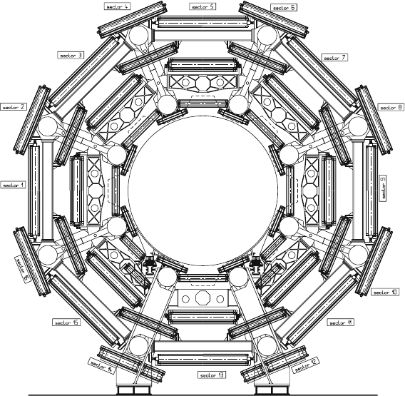
Fig. 11.24 Cross-sectional view of the barrel part of the ATLAS muon spectrometer. The cross
sections of the eight coils of the toroid magnet are visible as white circles; the chambers are located
inside and between them. The diameter of the barrel is approx. 22 m
(3) the multiple scattering in the chambers and the structural material traversed by
the particle.
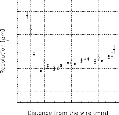
1. The accuracy achieved for an individual drift tube in the absence of a magnetic
field is depicted in Fig. 11.25 as a function of the distance between the track and
the wire. The working gas mixture for these measurements was 91%Ar + 4%N
2
+
5%CH
4
at 3 bar abs., which allows an r.m.s. measuring accuracy of approx. 75
μ
mto
be reached for drift distances above 3 mm. For smaller drift distances the accuracy
quickly becomes worse as the primary ionization fluctuation dominates. In view
of the problems of ageing in the high flux regime (cf. Sect. 12.6.4), it was later
decided to go to 93%Ar + 7%CO
2
at 3 bar abs. The unfavourable dependence of
drift velocity on the E-field of this gas had to be accepted. The resolution achieved
with the new mixture is shown in Fig. 7.19.
2. The geometrical integrity of each chamber is guaranteed by glueing the tubes
onto the frames. During the experiment, a laser calibration system will follow
the internal elastic deformations caused by changes of temperature or stress. For
the measurement of momentum it is important to know the relative positions of
the three chambers that together determine the sagitta of the particle track. For
388 11 Existing Drift Chambers – An Overview
Fig. 11.25 Measuring
accuracy of an individual drift
tube, without a magnetic
field. Full circles:
measurements; open circles:
simulation [RIE 00]
40
50
60
70
80
90
100
110
120
130
02468101214
this purpose, the chambers of this ‘tower’ are interconnected by laser rays seen
by position-calibrated detectors on the chambers.
3. The mechanical structures for the support of the magnet, the chambers, and
all the other detectors of the ATLAS experiment are almost all made of aluminium.
They represent a mass of material which causes a lot of Coulomb scattering in ad-
dition to that of the chambers proper. It may be quite different from one track to
another; on average it causes relative transverse momentum measurement errors
δ
p
T
/p
T
typically between 2 and 3%. The aluminium of the chambers themselves
contributes approx. 1%.
The overall momentum-measuring accuracy of the muon spectrometer is calcu-
lated to be roughly
δ
p
T
/p
T
= 0.1atp
T
= 1 TeV/c, dominated by (1) and (2), and
0.03 at p
T
= 10 GeV/c, dominated by (3).
11.5.6 A Large TPC System for High Track Densities
The NA49 experiment at the CERN SPS accelerator is dedicated to the study of
hadron production on fixed targets in proton-proton, proton-nucleus, and nucleus-
nucleus collisions [AFA 99]. A system of 4 large TPCs with a total sensitive volume
of 33 m
3
is the main instrument for tracking and dE/dx measurement. The incom-
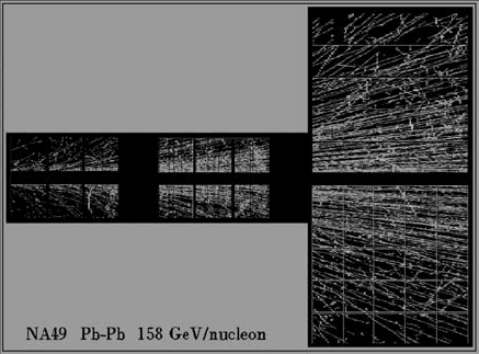
ing beam passes between them, compare Fig. 11.26. Central lead-lead collisions at
the beam momentum of 158 GeV/c per nucleon can produce more than a thousand
tracks in one event.
Of the four TPC modules, the two smaller ones are operated inside strong and
not very homogeneous vertical magnetic fields, the two larger ones outside. The
drift is vertical, the sensitive wire chamber end plates horizontal. The wire grids are
11.5 Large Cylindrical Drift Chambers of Type 2 389
Fig. 11.26 Top view of the four TPCs; the two ‘vertex chambers’ inside the magnetic field are on
the left, the two ‘main chambers’ to both sides of the beam outside the magnetic field are on the
right. A central Pb + Pb event is depicted in a slice only 7 mm high around the beam plane, in order
to be able to distinguish tracks in the projection
designed as in the ALEPH TPC but have a reduced distance between pads and sense
wires. Their total area amounts to 30 m
2
. Signals are read out only from the cathode
pads of which there are 182 000. A maximum of 234 pad rows is available for the
measurement of fully recorded tracks, but the actual number of signal clusters lies
approximately between 20 and 160, depending on track overlap and kinematics in
the given acceptance region. The authors estimate that an over-all position precision
of about ±0.20 mm has been achieved for isolated tracks, varying with the drift
length between ±0.15 and ±0.28 mm.
The separation of neighbouring tracks is a major challenge in this experiment.
The diffusion properties of the gas and the other detector parameters have been
designed with the aim to reach a charge distribution within typically 5 mm FWHM.
The authors show that track pairs with average distances above 1.6 cm are fully
detected, those with distances of 1.0 cm are detected with 50% efficiency. Further
improvements seem to be in reach. It is remarkable that the TPC technique can be
extended to record tracks in such high particle densities.
This was made possible by an increased density of cathode pads and the associ-
ated electronic channels. The entire front-end electronics up to the digital outputs is
mounted on the TPC readout chambers, the pad widths being not more than 3.5 or
5.5 mm.
The high particle density is a challenging environment also for particle identifi-
cation using dE/dx measurements. It is difficult to control the pulse height variation
with drift time which is partly caused by the baseline shift of the electronic signals,
partly by the widening of the measured charge clusters at the required threshold,
but only to a smaller degree by electron attachment. It is also not easy to correct for
electronic cross-talk at these high particle densities. Despite of these severe condi-
tions, the authors are able to report an r.m.s. resolution for the dE/dx measurement

390 11 Existing Drift Chambers – An Overview
of
σ
I
= 38%/
√
N
c
where the number N
c
of signal clusters lies between 20 and 160.
The method of charge estimation applied is the one of the truncated mean at the
50% level. The relativistic plateau is IR = 56% above minimum ionization.
Using the ratio
σ
I
/IR as a measure for the ability of particle identification one
can say that the NA49 TPC system reaches a similar level of identification ability as
the detectors listed in Tables 10.3 and 10.4, once the losses of signal clusters from
track overlap and acceptance limitation are taken into account.
11.6 Small Cylindrical Drift Chambers of Type 2
for Colliders (Vertex Chambers)
Vertex detectors are needed for the measurement of the (primary) interaction vertex
or any secondary vertices that may occur in an event from the decay of short-lived
particles. The charm, bottom and
τ
particles have lifetimes of the order of 10
−13
to
10
−12
s, so the tracks from the secondary vertices will miss the primary vertex by
correspondingly small distances, which are of the order of 30 to 300 μm. Ideally,
vertex chambers should have even better measurement accuracies.
This is the field where the fine-grained solid-state particle detectors with their su-
perb spatial resolution are often a better choice than gas drift chambers. These have
in their favour the simplicity of a proven technique and a somewhat better resis-
tance against high-radiation background. Also they are more easily extended over
large sensitive areas. Being closer to the interaction point they can often be built
smaller and with shorter wires than the large axial chambers, so that the wire posi-
tion can be extremely well defined. This is a prerequisite for the high measurement
accuracy achieved in the vertex chambers. When measuring the position of a vertex
inside the vacuum tube, multiple scattering in the wall of the tube is often a limiting
factor, which depends on the momentum of the extrapolated particle as well as on
the tube radius and the thickness of the wall.
In order to reach the best possible point-measuring accuracy and double-track
resolution, the sense wires have to be as close as possible to each other (cf. the
discussion in Sect. 11.8). The limit imposed by electrostatic stability depends on
the wire length and the detailed electrostatic pattern, and it becomes more severe at
higher gas pressures because of the corresponding higher voltages.
To find the correct gas, one has to balance the consequences of a slow ‘cool’
gas (see Sects. 2.2.4, 12.1) – slower electronics, high drift field with low diffu-
sion, sensitivity to field inhomogeneity through unsaturated drift velocity – with
the consequences of a fast ‘hot’ gas – faster electronics, lower sensitivity to field,
temperature and pressure variations.
These questions have been studied in detail for the more recent vertex detec-
tors. The chambers listed in Table 11.3 are again intended to represent the different
choices in the field. They are all axial drift chambers of type 2. The ones that reach
the highest precision are operated with slow cool gas at an elevated pressure. Hayes
has compared vertex drift chambers for the LEP and SLC detectors [HAY 88]. The

11.6 Small Cylindrical Drift Chambers of Type 2 for Colliders 391
Table 11.3 Some small drift chambers of type 2 (vertex chambers)
Name of experiment UA2 MARK J MARK II OPAL MAC ALEPH
Name of chamber JVD TEC DCVD VCH straw-VC ITC
Method of z measurement Charge division – – Time difference – Time difference
+stereo
Reference [BOS 89] [AND 86] [ALE 89] [CAR 90] [ASH 87] [DEL 90]
[AND 88a] [DUR 90] [OPA 91] [NEL 87] [BAR 89]
[AND 88b]
Geometry
Outer/inner radius (cm) 13/4 12/5 17/5 22/10 9/3.5 28/13
Length (cm) 100 58 55 100 43 200
No. of wires 1232 2750 1800 324 5136
No. of sense wires 208 168 190 648 324 960
No. of sense wires per cell (6) 13 14 19 12(6) 1 1
Sense-wire diameter (μm) 25 20 20 20 30 30
No. of measured points per track 13 14 19 18 6 8
Radial distance between sense wires (mm) (6) 6.4 2.4 2.9 5.0 (5.3) 6–10 11–19
Max. drift distance (cm) 2.5 1.3–2.6 3 0.8–1.9 0.35 0.47–0.65
Stereo angle (
◦
) 000400
Radial tilt of sense wire plane (
◦
) 0 ± 4150 – –