Blum W., Riegler W., Rolandi L. Particle Detection with Drift Chambers
Подождите немного. Документ загружается.


392 11 Existing Drift Chambers – An Overview
Table 11.3 (continued)
Gas and fields
Gas (percentage concentrations) Ar(60) CO
2
(80) CO
2
(92) Ar(00) Ar(49.5) Ar(50)
+C
2
H
6
(40)+i-C
4
H
10
(20)+C
2
H
6
(8)+CH
4
(10)+CO
2
(49.5)+C
2
H
6
(50)
+i-C
4
H
10
(2)+CH
4
(1)
Gas pressure (bar) 1 1.9 2 4 4 1
Electric drift field (kV/cm) 1 1.6 1.5 2.7 2–7 (70%) 3–5
Magnetic field (T) 0 0 0.47 0.4 0.6 1.5
Drift velocity (cm/μs) 5.2 0.7 0.6 4.0 1–3 (70%) 5.0
Approx. value of
ωτ
0 0 0.02 0.1 small small
Performance (1)
Point measuring accuracy 150 (b) 35 (b) 30 (b) 50 (b) 70 (c) (4) 100 (b)
σ
r
ϕ
(μm) 180 (c) (3) 40 (c) 50 (c) 55 (c) 45 (c) (3) 150 (c)
300 (c) (5)
Charge division or time difference 10 (b) – – 45 (c) – 30 (b)
accuracy
σ
z
(mm) 25 (c) (3)
35 (c) (5)
Double-track resolution
Δ
r
ϕ
(mm) 2 (b) 0.3 (b) (7) 0.5 (c) (8) 2.0 (c) 6.9 11 (a)
Impact-parameter accuracy (2) 87 (c) (3) 130 (c)
σ
t
(μm) 400 (c) 80 (b) 30 (c) 30 (c) 200 (c) (4)
1. The performance figures are based on (a) calculation and laboratory tests; (b) prototype, cosmic-ray or test-beam measurements; (c) measurements in the
running experiment.
2. Vertex chamber plus main tracking chamber – high-momentum tracks.
3. Isolated tracks.
4. Multihadron events, including multiple scattering.
5. Multihadron events, average multiplicity 31 to 35.
6. Numbers in brackets refer to the OPAL stereo cell.
7. Track separation at which 50% of the tracks are correctly resolved.
8. Track separation at which approx. 100% of the tracks are resolved.
11.6 Small Cylindrical Drift Chambers of Type 2 for Colliders 393
proceeding of a workshop dedicated mostly to advanced vertex detectors [VIL 86]
offers some more material that describes the state of the art in 1986. A short review
on straw chambers was given by Toki [TOK 90].
Among the more recent vertex detectors we find the drift chambers with the best
measuring accuracy that are integrated into particle experiments. Higher accuracy
has only been achieved with more specialized devices. These will be briefly dis-
cussed in Sect. 11.8.
11.6.1 Six Representative Chambers
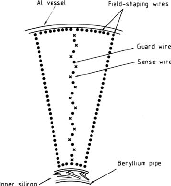
The JDV of the UA2 experiment had to work in severe background conditions at the
¯
pp collider. The drift cell, shown in Fig. 11.27, has a geometry similar to that of the
OPAL chamber; it operates in a fast gas at atmospheric pressure, and at the saturated
drift velocity. The point-measuring accuracy achieved in the test beam (150 μm)
deteriorated a lot (300 μm) in the large-multiplicity events of the real experiment.
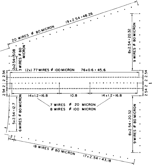
The vertex detector of the MARK-J experiment is built according to the principle
of the ‘time expansion chamber’, or ‘TEC’. Introduced by Walenta [WAL 79], it is
characterized by a wire amplification region strictly separated from the drift region
by a dense wire grid or wire mesh. The drift cell of the MARK-J TEC is shown in
Fig. 11.28 and represents one twelfth of the entire chamber. One recognizes the two
wedge-shaped drift spaces on either side of the 4 mm wide amplification region; they
are not symmetrical because the sense/field wire planes are inclined alternatively by
± 4
◦
in the service of pattern recognition. The gas is a slow and cool mixture of
80% CO
2
and 20% i-C
4
H
10
. The sense wires are read out by 100 MHz analogue-
to-digital converters (flash-ADCs). An average point-measuring accuracy of 40 μm
was determined with Bhabha events.
Fig. 11.27 Drift cell of the
UA2 JVD chamber
394 11 Existing Drift Chambers – An Overview
Fig. 11.28 Drift cell of the TEC of the MARK J experiment
The MARK II vertex chamber was designed for the SLAC Linear Collider with
its small beam pipe, which has a radius of 2.5 cm. The inner wall of the chamber
and the beam pipe represent a total of 0.6% of a radiation length, thus contributing
only 45 μmGeV/c to the Coulomb scattering limit S
c
discussed in Sect. 8.4.2.
The wires run parallel to the axis, and they are organized in cells that each span
the full radial range between 5 and 17 cm (see Fig. 11.29). In the middle of each cell
is the sense/field-wire plane, inclined by an azimuthal tilt angle of 15
◦
; it contains 41
field wires, spaced out by 2.9 mm, and 40 sense wires between them. Two planes of
grid wires, 1.8 mm on either side, separate the amplification region from the drift re-
gion and provide a certain amount of focussing for the electron drift paths, similar to
what happens in the ‘TEC’. The cathode planes with 59 wires, spaced out by 2 mm,
bisect the angle between the sense/field-wire planes of two adjacent cells. Each drift
cell is thus limited by the two cathode planes at radially increasing potentials and
additional potential wires at the cylindrical surfaces. They complete the field cage
which provides a uniform field despite the wedge of drift space it encloses.
The OPAL vertex chamber is constructed for LEP whose beam pipe is much
larger than the one at the SLC. With its radius of 7.8 cm and its thickness of 0.86%
radiation lengths the OPAL pipe contributes a Coulomb scattering limit S
c
= 110
GeV/c to the impact-parameter resolution.
11.6 Small Cylindrical Drift Chambers of Type 2 for Colliders 395
Fig. 11.29 Drift cell of the
VCDV of the MARK II
experiment
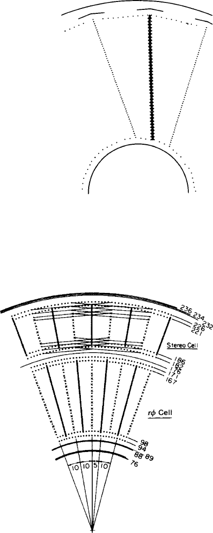
The wire pattern is shown in Fig. 11.30. The chamber is 100 cm long. It has one
axial and one stereo layer at 20
◦
. The axial layer between radii of 9.4 and 17.1 cm
is of the ‘jet chamber’ type and has 36 radial planes of sense/field wires, each con-
taining 12 sense wires spaced out by 5 mm, and the field wires between them. The
left–right ambiguity, which does not occur when the sense-wire plane is tilted with
Fig. 11.30 Wire pattern of the
OPAL vertex chamber
396 11 Existing Drift Chambers – An Overview
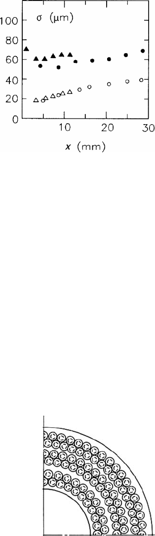
Fig. 11.31 Measured
prototype vertex chamber
resolutions
σ
as a function of
the drift distance x after
[HAY 86]. Triangles:OPAL;
circles: MARK II. Open
symbols: slow gas (CO
2
(80%) + i-C
4
H
10
(20%) at 2.5
bar for OPAL, CO
2
(92%) +
i-C
4
H
10
(8%) at 3 bar for
MARK II); full symbols:fast
gas Ar (50%) + C
2
H
4
(50%)
at 3 bar for both chambers
respect to the radial direction, is resolved by staggering alternative sense wires by
± 41μm which increases to ± 80μm in the middle of the wires, owing to their
electrostatic forces. The 10
◦
in azimuth between two neighbouring sense/field-wire
planes are bisected by the radial-wire-cathode planes, so that the maximal drift dis-
tance varies with radius from 9 to 15 mm. There is a double layer of potential wires
to close the field cage of each cell. This produces a field that is uniform and at right
angles to the sense/field-wire plane by grading the cathode voltages appropriately.
The stereo layer occupies the radial space between 18.2 and 22.6 cm; it is orga-
nized in the same fashion, but there are only half as many sense wires in this layer.
The maximal drift distances are now between 1.6 and 1.9 cm.
Each of the 648 sense wires is read out at both ends and is timed with a
constant-fraction discriminator and a time-to-digital converter (TDC). Thus, there
is a coordinate measurement along the wire direction from the time difference, in
addition to the azimuthal coordinate determined from the average of the two times.
The OPAL vertex detector is operated with the slow mixture CO
2
(92%) +
i-C
4
H
10
(8%) at 2.5 bar. The space resolution achieved with the drift-time mea-
surement is depicted in Fig. 11.31 as as function of the drift distance, both for the
OPAL and the MARK II vertex detector prototypes. The resolution has reached the
remarkable range between 20 and 40 μm for drift distances up to 3 cm. With fast gas
and the same electronics, the resolutions were two or three times worse [HAY 88].
Fig. 11.32 One quarter of the
end plate of the MAC straw
vertex chamber (for
dimensions, consult
Table 11.3)
11.7 Drift Chambers of Type 3 397
Fig. 11.33 Drift cells of the
ALEPH Inner Track Chamber
The drift chambers of the last two examples in our list are again constructed
from cells that are built around the individual sense wires. The vertex chamber of
the MAC detector consists of many thin tubes of aluminized Mylar foil with the
proportional wire in the centre. These ‘straws’ provide exact cylindrical symmetry
and a high degree of electrical shielding between sense wires. Their inner diameter
is 6.9 mm, and the wall thickness 50 μm. In Fig. 11.32 we see the layout of the
vertex chamber end plate.
The cylindrical geometry produces a drift field that increases with the inverse
distance from the wire. The drift velocity therefore also changes, depending on the
gas used. In Table 11.3 we have indicated ranges for the field and the velocity that
are valid in the outer 70% of the drift region. In a similar design for the MARK III
experiment [ADL 89], the gas mixture was argon–ethane with a more uniform, and
higher, velocity; the achieved point-measuring accuracy was comparable. Toki has
recently reviewed straw chambers [TOK 90].
The purpose of the ALEPH-ITC is the production of an early trigger signal as
well as precise tracking (a solid-state microstrip detector is mounted in addition).
The drift cell is a group of six field wires around each proportional wire, in a flat
hexagonal arrangement, which is depicted in Fig. 11.33. Each hexagon is character-
ized by two shape parameters, the diameters in the radial and in the circumferential
directions; both vary with the wire layer. A time-difference measurement is the basis
for a determination of the axial coordinate. It takes 0.5 μs for a trigger decision in
r −
φ
and 2.5 μsinr −
ϕ
−z.
11.7 Drift Chambers of Type 3
An ionization track created in the sensitive gas volume of a type 3 chamber drifts
to one of the end faces that delimit the volume. It is there that the amplification and
signal generation take place. Large chambers have drift lengths of one or several
metres. If a magnetic field is present in a TPC, it is parallel to the drift field, and
in this orientation it can greatly improve the transverse diffusion of the travelling
electrons, on account of the magnetic anisotropy of diffusion; see Sect. 2.2.6.
With the length of the drift path we have a correspondingly high drift time – often
many tens of microseconds for electrons and several seconds for ions. This makes
long type 3 chambers unsuited for measuring events at very high rates because the
398 11 Existing Drift Chambers – An Overview
space charge from previous events in the drift space will distort the tracks. Ion shut-
ters (‘gating grids’ – see Chap. 9) are suitable tools for reducing the amount of ion
current that flows back into the drift volume from the amplification region.
The length of the drift path also sets severe requirements on the uniformity of the
electric and magnetic fields: a non-uniformity of one per cent may cause transverse
displacements of the order of one per cent of the drift length.
Finally we mention gas purity. Electrons may be attached to gas components that
are present even in extremely low concentrations, the result being a signal loss that
increases with the drift path. We have described electron attachment in Sect. 2.2.7.
Still a TPC can be a very powerful universal track detector. If all the above-
mentioned problems have been overcome, one profits from its advantages: with its
wires strung on the inner surface of the end-plates rather than through the volume
the construction can be modular and technically very convenient. For every track
segment one achieves an intrinsically three-dimensional coordinate determination –
two coordinates being given by the position in the end plate of the pick-up electrodes
that collect the segment, the third being measured through the drift time.
Furthermore, with a TPC one can totally avoid the dilemma of the Lorentz an-
gle: if one puts B and E parallel in the drift volume, there is no shift of the drift
direction, and the magnetic field may be increased as far as technically feasible, the
gas pressure can be kept low, and the diffusion may be dramatically reduced; cf. the
discussion in Chap. 12.
11.7.1 Double-Track Resolution in TPCs
The measurement of a track produces a dead region around this track where the
chamber is insensitive to the measurement of other tracks. In a TPC with cathode
pads, this dead region is a tube around the track, whereas in axial wire chambers and
in TPCs with wire measurement it is a flat region that extends along the full length
of the wire.
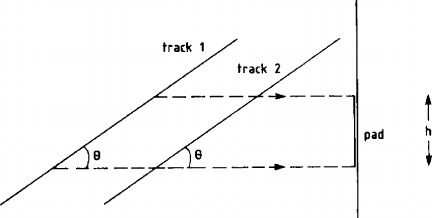
Concerning track measurements with pads, overlap occurs on the pad when it is
still occupied with the pulse of a first track at a time when the pulse of a second
track begins. The pulse length T is given by the intrinsic electronic pulse length t
e
plus the drift-time difference t
d
of the electrons from one track that reach the pad
at different times, because of a track inclination
θ
and the size h of the pad. With
reference to Fig. 11.34 we have an overlap region
Δ
z in the drift direction, equal to
Δ
z = ut
e
+ ut
d
= ut
e
+ h/tan
θ
, (11.1)
where u is the drift velocity and
θ
the angle between the track and the normal to the
pad (typically the polar angle). In Table 11.4 double-track resolutions are quoted for
two polar angles.
In the azimuthal direction, two tracks will have to be 2 or 3 pad widths apart in
order to be separable; a practical average may be 2.5 pad widths.
11.7 Drift Chambers of Type 3 399
Fig. 11.34 Two inclined
tracks; the first electrons from
track 1 arrive on the pad at
thesametimeasthelast
electrons from track 2
11.7.2 Five Representative TPCs
There are four large cylindrical TPCs that have been built around the interaction
points of e
+
e
−
colliders (PEP-4, TOPAZ, ALEPH, DELPHI); see Table 11.4. They
are all very similar because their construction followed closely the principles estab-
lished by the pioneers in this field, the designers of the PEP-4 TPC. These chambers
are cylinders around the colliding beams; the drift direction is parallel to the mag-
netic field and to the direction of the incoming particles. The drift volume is divided
in the middle by the high-voltage membrane which is set at a negative potential so
that the circular end plates with their detection electrodes can be kept at earth po-
tential (Fig. 11.35). The disposition of the various layers of electrodes in the end
plates is seen in Fig. 11.36a, and Fig. 11.36b shows the arrangement of the pads in
the cathode plane in the example of the ALEPH TPC. The inner and outer cylin-
der mantles that delimit the gas volume also carry the high-voltage electrode rings,
which shape the axial, homogeneous electric drift field.
The four large TPCs differ among each other in two respects: the PEP-4 and
TOPAZ TPCs are constructed to work at higher gas pressure and with straight pad
rows; the ALEPH and DELPHI TPCs have ambient pressure and circular pad rows.
The gas pressure is an important choice for any drift chamber (see the discussion in
Sect. 12.5), but for TPCs one must consider in addition the magnetic anisotropy of
diffusion – the transverse width of the diffusion cloud increases with the pressure.
The circular pad rows in the two TPCs at CERN are an improvement over the (ear-
lier) straight rows, since for stiff radial tracks they do not cause the measurement
error that was called the ‘angular pad effect’ in Sect. 7.2.
Whereas the width of the pad determines the number of electronic channels and
hence the cost of the project, the length of the pads (extent in the radial direction)
is chosen as a balance between the largest possible signal and a loss of accuracy
of lower-momentum tracks, owing to the angular pad effect (cf. Sect. 7.3.3). Also,
long pads deteriorate the two-track separation for steep tracks (Sect. 11.7.1). The
long pads in the ALEPH TPC reflect a choice in favour of a larger signal.
The problem of track overlap may be quantified as a loss of tracks rather than
points specifying the minimum opening angle
Δ
α
measured between two tracks at
the vertex, below which losses are observed. The minimum opening angle is smaller
for pairs with opposite curvature because the magnetic field bends them apart. Such

400 11 Existing Drift Chambers – An Overview
Table 11.4 Some TPCs built around colliders
Name of experiment PEP 4 TOPAZ ALEPH DELPHI CDF(1)
Reference [LYN 87] [KAM 86] [DEC 90] [BRA 89] [SNI 88]
[AVE 89] [SHI 88] [ATW 91] [AAR 90]
[SIE 90]
Geometry
Outer/inner radius (cm) 100/20 127/30 180/31 116/32 21/7
Drift length (cm) 2 × 100 2 × 122 2 × 220 2 × 134 2 × 15
Number of sense wires 2196 2800 6336 1152 384
Sense-wire spacing (mm) 4 4 4 4 6.3
Number of pads 13824 8192 41004 20160 384
Pad dimensions (r ×r
ϕ
) (mm
2
)7× 7.5 12 × 10 (4) 30 × 68× 741× 14
Max. no. of measured points per outgoing track
On pads 15 10 21 16 3
On wires 183 175 338 192 24
Gas and fields
Gas (percentage fractions) Ar(80)
+ CH
4
(20)
Ar(90)
+ CH
4
(10)
Ar(90)
+ CH
4
(10)
Ar (80)
+ CH
4
(20)
Ar(50)
+ C
2
H
6
(50)
Gas pressure (bar) 8.5 3.5 1 1 1
Electric drift field (kV/cm) 0.55 0.35 0.12 0.15 0.25
Magnetic field (T) 1.32 1.0 1.5 1.2 1.5
Drift velocity (cm/μs) 5 5.3 5.0 6.7 4.3
Approx. value of
ωτ
1.5 4.9 7 5.4 3.5

11.7 Drift Chambers of Type 3 401
Table 11.4 (continued)
Performance (2)
Point-measurement error radial tracks
On pads:
σ
r
ϕ
(mm) 0.15 (c) 0.20 (c) 0.17 (c) 0.18 (c) 0.4
σ
z
(mm) at 90
◦
/30
◦
0.16/(c) 0.3/1.0 (c) 0.74/2 (c) 0.9 (c) –
On wires:
σ
z
(mm) 0.3/1.0(c) 2 (b) 0.9 (c) 0.4–1
Double-track resolution 2.4 (c) 2.5 (a) 1.5 (b) 1.5 (c) –
On pads:
Δ
r
φ
(cm)
Δ
z
(cm) at 90
◦
/30
◦
3/3 (a) 2/6 (b) 1.5 (c) –
Δ
α
(mrad) 25–40 (c) 35 (c)
On wires:
Δ
z
(cm) 3 (a) 2 (b) 1.5 (c) 0.5–1.5
Accuracy of momentum measurement (3) 0.009 (c) 0.015 (c) 0.0012 (c) –
δ
p
t
/p
2
t
(GeV/c)
−1
Accuracy of momentum measurement (5) 0.0065 (c) 0.0008 (c) 0.0015 (c) –
δ
p
t
/p
2
t
(GeV/c)
−1
1. Numbers are given for each one of the 8 TPCs (‘modules’), each having two halves with opposite drift directions.
2. The performance figures are based on (a) calculation and laboratory tests; (b) prototype and test-beam measurements; (c) measurements in the running
experiment
3. High p
t
, full track length, TPC alone.
4. Zig-zag shape along r
ϕ
,depth± 2 mm.
5. High p
t
, full track length, TPC plus other detectors.