Bird R.B., Stewart W.E., Lightfoot E.N. Transport Phenomena
Подождите немного. Документ загружается.

s10.7
Heat Conduction in a Cooling Fin
307
Region 23:
At the two fluid-solid interfaces we can write Newton's law of cooling:
Surface
0:
Surface 3:
Addition of the preceding five equations gives an equation for
T,
-
T,.
Then the equation is
solved for
qo
to give
We now define an "overall heat transfer coefficient based on the inner surface"
Uo
by
Combination of the last two equations gives, on generalizing to
a
system with
n
annular
layers,
The
subscript
"0"
on
Uo
indicates that the overall heat transfer coefficient is referred to the
radius
ro.
510.7
HEAT
CONDUCTION IN A COOLING FIN'
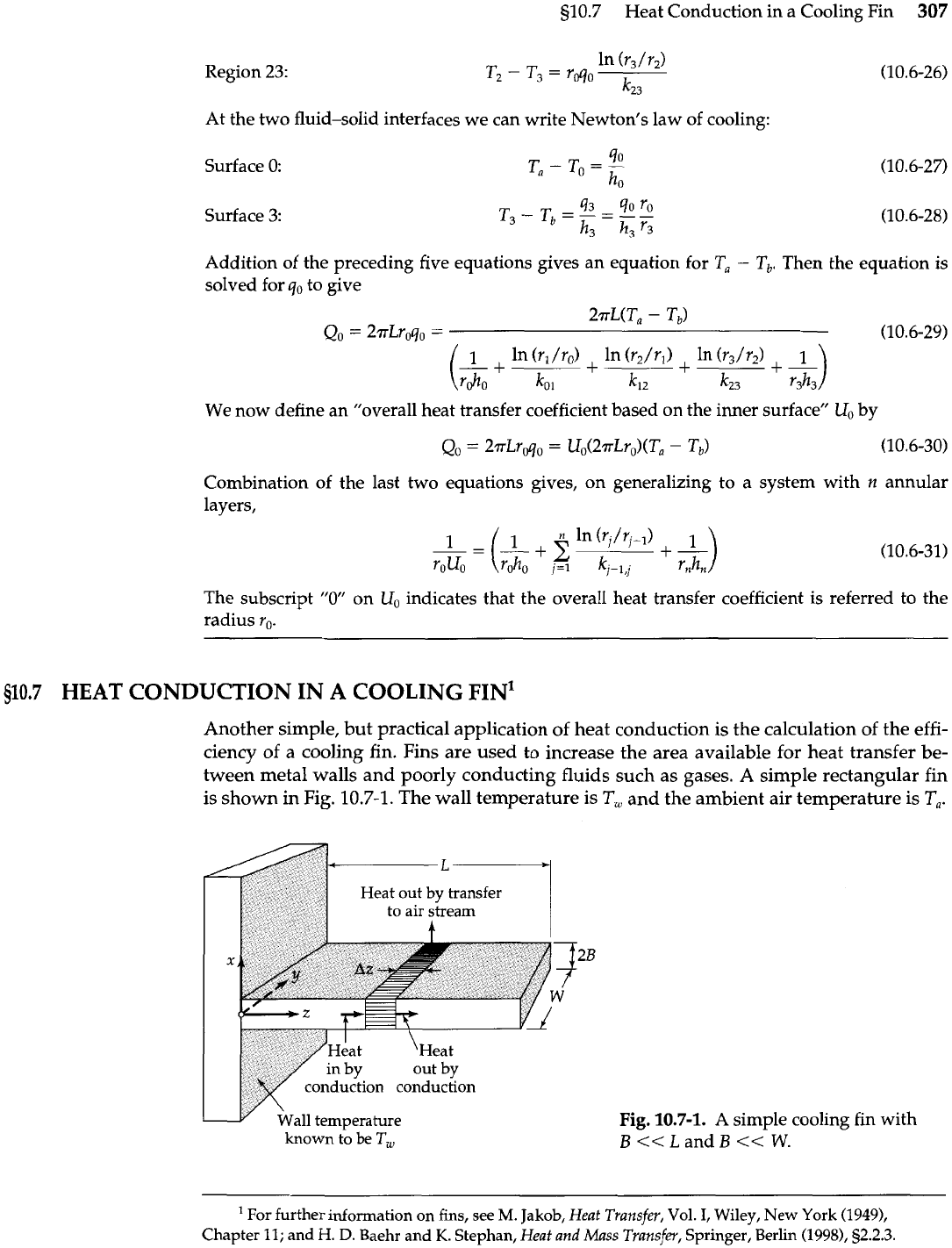
Another simple, but practical application of heat conduction is the calculation of the effi-
ciency of a cooling fin. Fins are used to increase the area available for heat transfer be-
tween metal walls and poorly conducting fluids such as gases. A simple rectangular fin
is shown
in
Fig.
10.7-1.
The wall temperature is
T,
and the ambient air temperature is
T,.
wall temperature
known to be
T,
Fig.
10.7-1.
A simple cooling fin with
B<<LandB<<
W.
For further information
on
fins,
see
M.
Jakob,
Heat Transfer,
Vol.
I,
Wiley, New York
(19491,
Chapter
11;
and
H.
D.
Baehr and
K.
Stephan,
Heat and Mass Transfeu,
Springer, Berlin
(1998),
52.2.3.
308
Chapter
10
Shell Energy Balances and Temperature Distributions in Solids and Laminar Flow
A
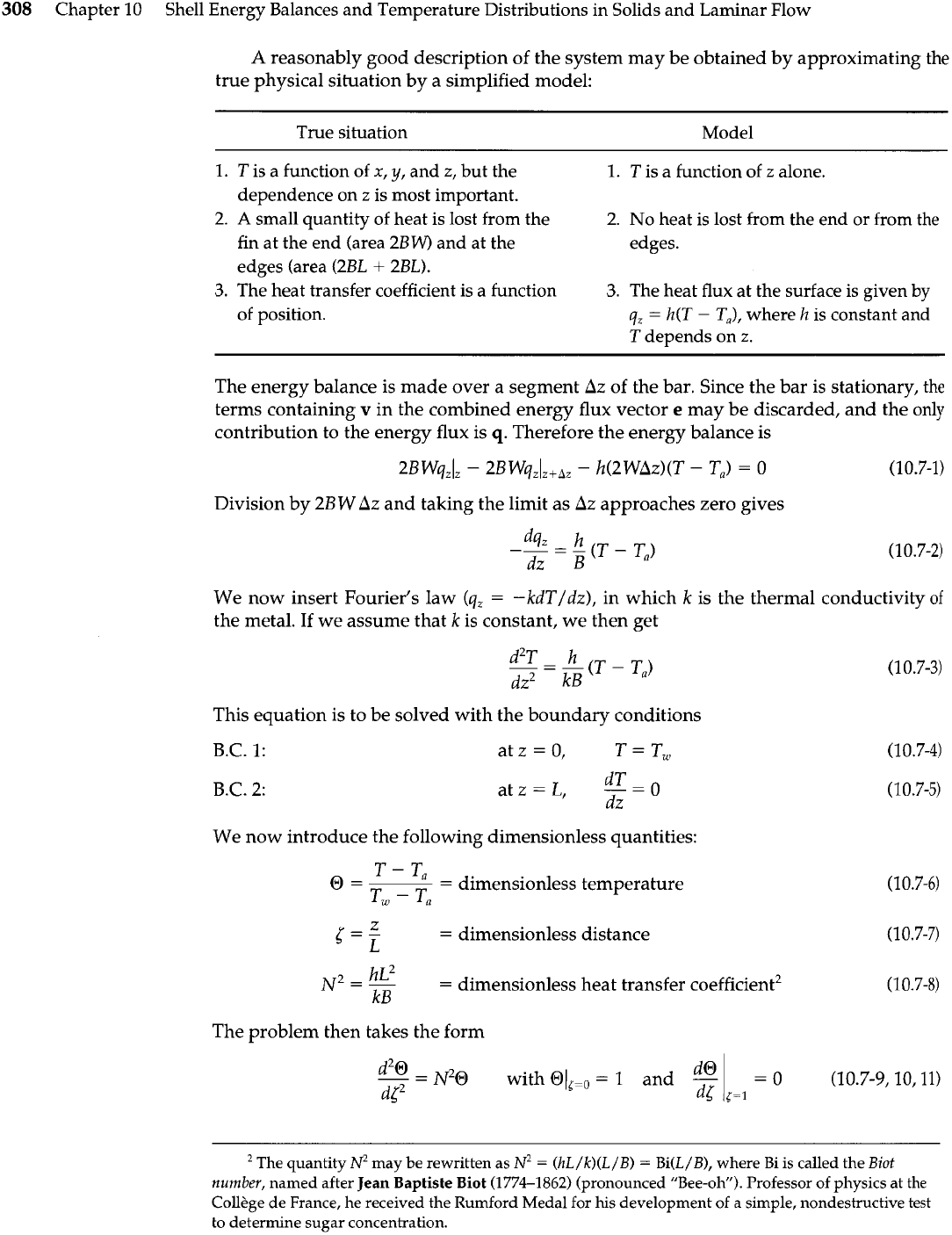
reasonably good description of the system may be obtained by approximating the
true physical situation by a simplified model:
True situation Model
1.
T
is a function of
x,
y,
and z, but the
1.
dependence on
z
is most important.
2.
A
small quantity of heat is lost from the
2.
fin at the end (area 2BW) and at the
edges (area (2BL
+
2BL).
3.
The heat transfer coefficient is a function
3.
of position.
T is a function of z alone.
No
heat is lost from the end or from the
edges.
The heat flux at the surface is given
by
q,
=
h(T
-
T,), where
h
is constant and
T
depends on z.
The energy balance is made over a segment
Az
of the bar. Since the bar is stationary, the
terms containing
v
in the combined energy flux vector
e
may be discarded, and the only
contribution to the energy flux is
q.
Therefore the energy balance is
Division by
2BW
Az
and taking the limit as
Az
approaches zero gives
We now insert Fourier's law
(q,
=
-kdT/dz), in which
k
is the thermal conductivity
of
the metal. If we assume that
k
is constant, we then get
This equation is to be solved with the boundary conditions
B.C.
1: at
z
=
0, T
=
T,
B.C.
2: atz=L,
--
dTO
dz
We now introduce the following dimensionless quantities:
T
-
T,
@=--
-
dimensionless temperature
Tw
-
T',
Z
5
=
-
L
=
dimensionless distance
2
-
hL2
N
-
-
=
dimensionless heat transfer coefficient2
kB
(10.7-8)
The problem then takes the form
--
d2@
-
N20
with
@Ii=.
=
1
and
-
(10.7-9,10,11)
dl2
The quantity may be rewritten as
N2
=
(hL/k)(L/B)
=
Bi(L/B), where Bi is called the Biot
number,
named after Jean Baptiste Biot
(1774-1862)
(pronounced "Bee-oh"). Professor of physics at
the
CollPge de France, he received the Rumford Medal for his development of
a
simple, nondestructive test
to determine sugar concentration.
s10.7 Heat Conduction in a Cooling Fin
309
Equation 10.7-9 may be integrated to give hyperbolic functions (see Eq. C.l-4 and
9C.5).
When the two integration constants have been determined, we get
O
=
cosh
N{
-
(tanh
N)
sinh
N{
(10.7-12)
This may be rearranged to give
cosh N(1
-
5)
cosh
N
This result is reasonable only if the heat lost at the end and at the edges is negligible.
The "effectiveness" of the fin surface is defined3 by
actual rate of heat loss from the
fin
"
=
rate of heat loss from an isothermal fin at
T,.
(10.7-14)
For the problem being considered here
is then
in which
N
is the dimensionless quantity defined in Eq. 10.7-8.
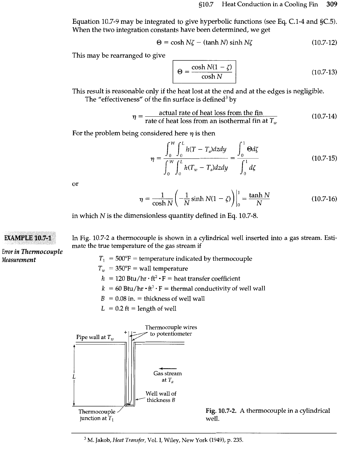
In
Fig.
10.7-2 a thermocouple is shown in a cylindrical well inserted into a gas stream. Esti-
mate the true temperature of the gas stream if
Error
in
Thermocouple
Measurement
TI
=
500°F
=
temperature indicated by thermocouple
T,
=
350°F
=
wall temperature
h
=
120 Btu/hr. ft2
F
=
heat transfer coefficient
k
=
60 Btu/hr ft3
.
F
=
thermal conductivity of well wall
B
=
0.08 in.
=
thickness of well wall
L
=
0.2 ft
=
length of well
Thermocouvle wires
Pipe wall
at
T,.
+
to potentlometer
Well wall of
-
thickness
B
-
Thermocouple
Fig.
10.7-2.
A
thermocouple in a cylindrical
junction at
well.
M.
Jakob,
Heat Transfer,
Vol.
I,
Wiley, New York
(19491,
p.
235.
310
Chapter 10
Shell Energy Balances and Temperature Distributions in Solids and Laminar Flow
SOLUTION
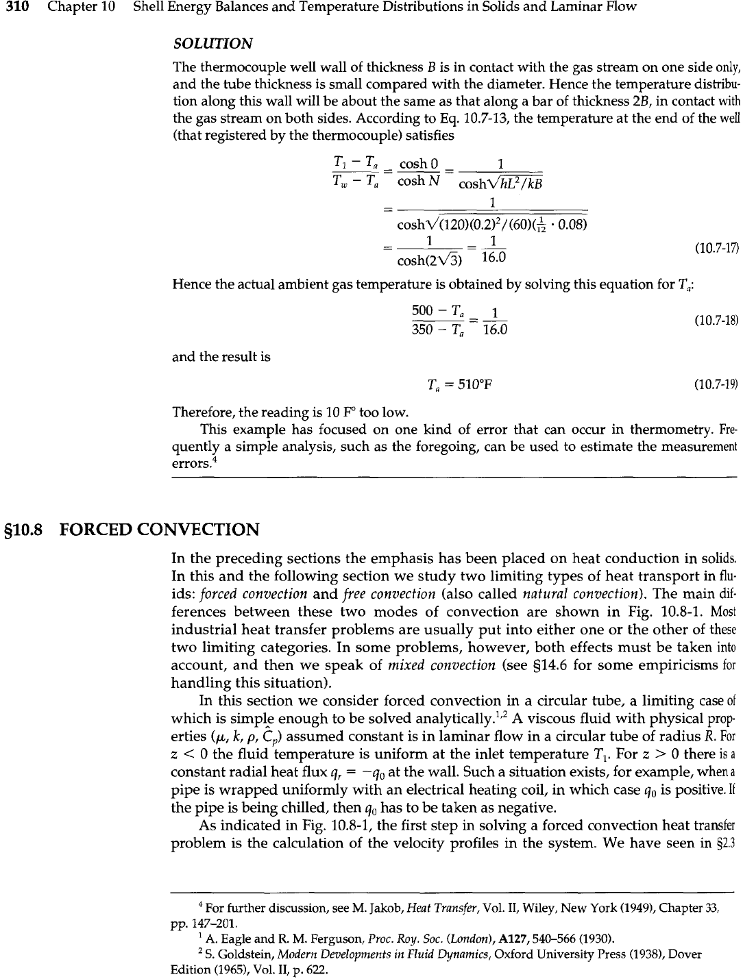
The thermocouple well wall of thickness
B
is in contact with the gas stream on one side
only,
and the tube thickness is small compared with the diameter. Hence the temperature distribu-
tion along this wall will be about the same as that along a bar of thickness 2B, in contact
with
the gas stream on both sides. According to
Eq.
10.7-13, the temperature at the end of the well
(that registered by the thermocouple) satisfies
Hence the actual ambient gas temperature is obtained by solving this equation for
T,:
and the result is
Therefore, the reading is 10
I?'
too low.
This example has focused on one kind of error that can occur in thermometry.
Fre-
quently a simple analysis, such as the foregoing, can be used to estimate the measurement
errors4
510.8
FORCED CONVECTION
In the preceding sections the emphasis has been placed on heat conduction in solids.
In this and the following section we study two limiting types of heat transport in
flu-
ids:
forced convection
and
free convection
(also called
natural
convection).
The main
dif-
ferences between these two modes of convection are shown in Fig.
10.8-1.
Most
industrial heat transfer problems are usually put into either one or the other
of
these
two limiting categories. In some problems, however, both effects must be taken
into
account, and then we speak of
mixed convection
(see 514.6 for some empiricisms
for
handling this situation).
In this section we consider forced convection in a circular tube, a limiting case
of
which is simple enough to be solved analyti~all~.',~
A
viscous fluid with physical prop-
erties
(p,
k,
p,
Cp)
assumed constant is in laminar flow in a circular tube of radius
R.
For
z
<
0
the fluid temperature is uniform at the inlet temperature
TI.
For
z
>
0
there
is
a
constant radial heat flux
q,
=
-qo
at the wall. Such a situation exists, for example, when
a
pipe is wrapped uniformly with an electrical heating coil, in which case
qo
is positive.
If
the pipe is being chilled, then
q,,
has to be taken as negative.
As indicated in Fig. 10.8-1, the first step in solving a forced convection heat transfer
problem is the calculation of the velocity profiles in the system. We have seen in
52.3
For further discussion, see
M.
Jakob,
Heat Transfer,
Vol.
11,
Wiley, New York (1949), Chapter
33,
pp. 147-201.
A.
Eagle and
R.
M.
Ferguson,
Proc. Roy. Soc. (London),
A127,540-566 (1930).
S.
Goldstein,
Modern Developments in
Fluid
Dynamics,
Oxford
University
Press (1938), Dover
Edition (1965),
Vol.
11,
p.
622.
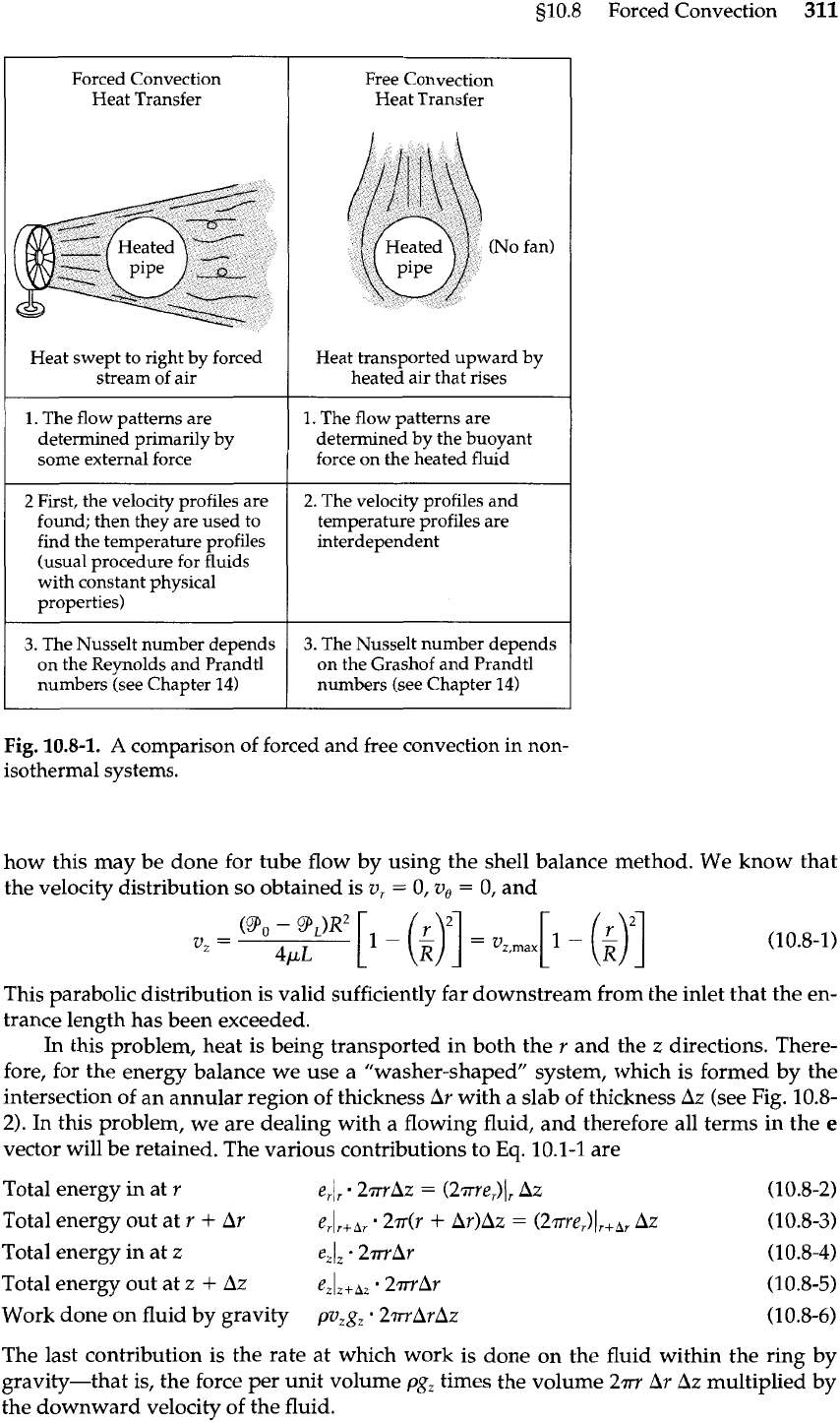
510.8
Forced Convection
311
Forced Convection
Heat Transfer
Heat swept to right by forced
stream of air
1.
The flow patterns are
determined primarily by
some external force
2
First, the velocity profiles are
found; then they are used to
find the temperature profiles
(usual procedure for fluids
with constant physical
properties)
3.
The Nusselt number depends
on the Reynolds and Prandtl
numbers (see Chapter
14)
Free Convection
Heat Transfer
Heat transported upward by
heated air that rises
1.
The flow patterns are
determined by the buoyant
force on the heated fluid
2.
The velocity profiles and
temperature profiles are
interdependent
3.
The Nusselt number depends
on the Grashof and Prandtl
numbers (see Chapter
14)
Fig.
10.8-1.
A
comparison of forced and free convection
in
non-
isothermal systems.
how this may be done for tube flow by using the shell balance method. We know that
the velocity distribution so obtained is v,
=
0,
v,
=
0, and
This parabolic distribution is valid sufficiently far downstream from the inlet that the en-
trance length has been exceeded.
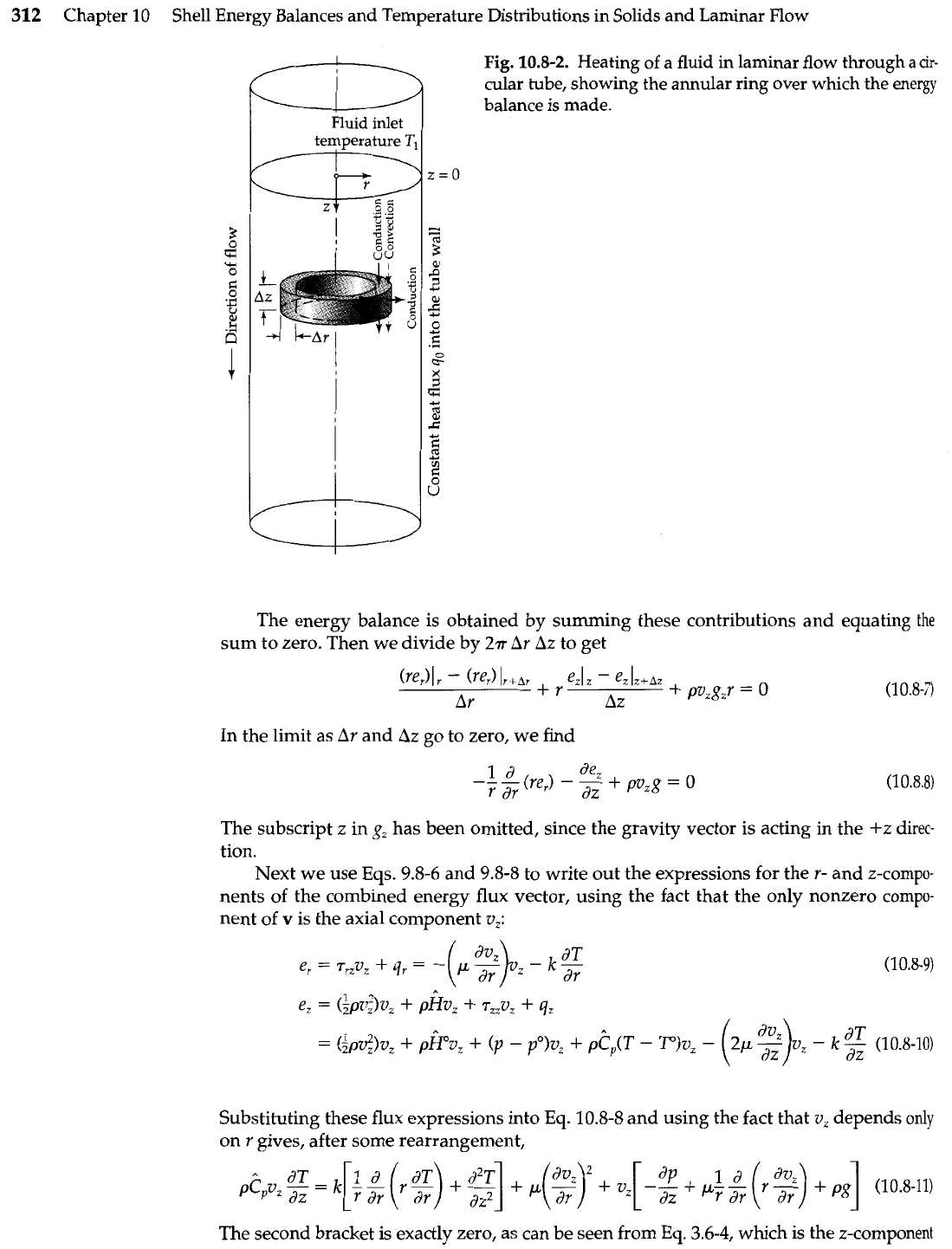
In this problem, heat is being transported in both the r and the z directions. There-
fore, for the energy balance we use
a
"washer-shaped" system, which is formed by the
intersection of an annular region of thickness Ar with a slab of thickness Az (see Fig. 10.8-
2). In this problem, we are dealing with a flowing fluid, and therefore all terms in the
e
vector will be retained. The various contributions to
Eq.
10.1-1 are
Total energy in at r
e,l,
2mAz
=
(2me,)Jr Az (10.8-2)
Total energy out at
r
+
Ar
erlr+hr 27dr
+
Ar)Az
=
(2~re,)),+~~
AZ
(10.8-3)
Total energy in at z ezlZ -2mAr (10.8-4)
Total energy out at z
+
Az
eZlz+~,
2m.A~
(10.8-5)
Work done on fluid by gravity pv,g,
2.rruArA.z (10.8-6)
The last contribution is the rate at which work is done on the fluid within the ring by
gravity-that is, the force per unit volume
pg,
times the volume 2m Ar Az multiplied by
the downward velocity of the fluid.
312
Chapter
10
Shell Energy Balances and Temperature Distributions in Solids and Laminar Flow
I
u
Fluid
inlet
temperature
T:
Fig.
10.8-2.
Heating of a fluid in laminar flow through
a
cir-
cular tube, showing the annular ring over which the energy
balance is made.
The energy balance is obtained by summing these contributions and equating
the
sum to zero. Then we divide by
2v
Ar Az
to get
In
the limit as
Ar
and
Az
go to zero, we find
The subscript z in
g,
has been omitted, since the gravity vector is acting in the
+z
direc-
tion.
Next we use Eqs. 9.8-6 and 9.8-8 to write out the expressions for the
r-
and z-compo-
nents of the combined energy flux vector, using the fact that the only nonzero compo-
nent of
v
is the axial component
v,:
Substituting these flux expressions into Eq. 10.8-8 and using the fact that
v,
depends
only
on
r
gives, after some rearrangement,
The second bracket is exactly zero, as can be seen from Eq. 3.6-4, which is the z-component
s10.8
Forced Convection
313
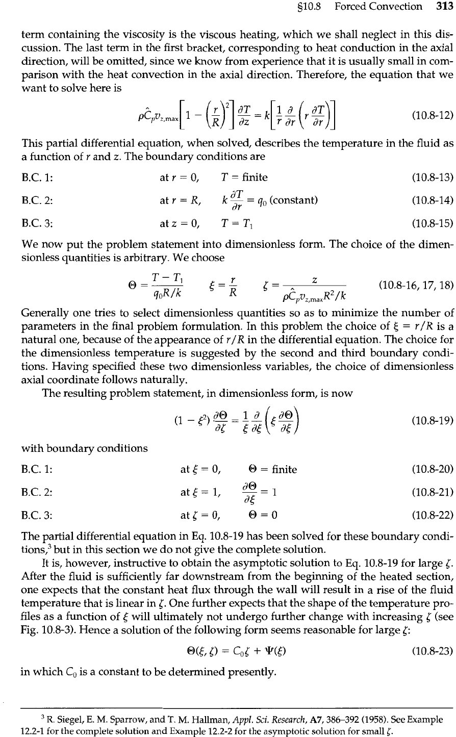
term containing the viscosity is the viscous heating, which we shall neglect in this dis-
cussion. The last term in the first bracket, corresponding to heat conduction in the axial
direction, will be omitted, since we know from experience that it is usually small in com-
parison with the heat convection in the axial direction. Therefore, the equation that we
want to solve here is
This partial differential equation, when solved, describes the temperature in the fluid as
a function of r and
z.
The boundary conditions are
B.C. 1: at
r
=
0,
T
=
finite (10.8-13)
B.C. 2:
dT
at r
=
R,
k
-
=
qo
(constant)
dr
(10.8-14)
B.C. 3: at
z
=
0,
T
=
TI
(10.8-15)
We now put the problem statement into dimensionless form. The choice of the dimen-
sionless quantities is arbitrary. We choose
Generally one tries to select dimensionless quantities so as to minimize the number of
parameters in the final problem formulation. In this problem the choice
of
5
=
r/R is a
natural one, because of the appearance of r/R in the differential equation. The choice for
the dimensionless temperature is suggested by the second and third boundary condi-
tions. Having specified these two dimensionless variables, the choice of dimensionless
axial coordinate follows naturally.
The resulting problem statement, in dimensionless form, is now
with boundary conditions
B.C. 1: at
t
=
0,
(3
=
finite (10.8-20)
B.C. 2:
-
1
at(= I,
---
at
(10.8-21)
B.C. 3: at
5
=
0,
a
=
o
(10.8-22)
The partial differential equation in Eq. 10.8-19 has been solved for these boundary condi-
tions: but in this section we do not give the complete solution.
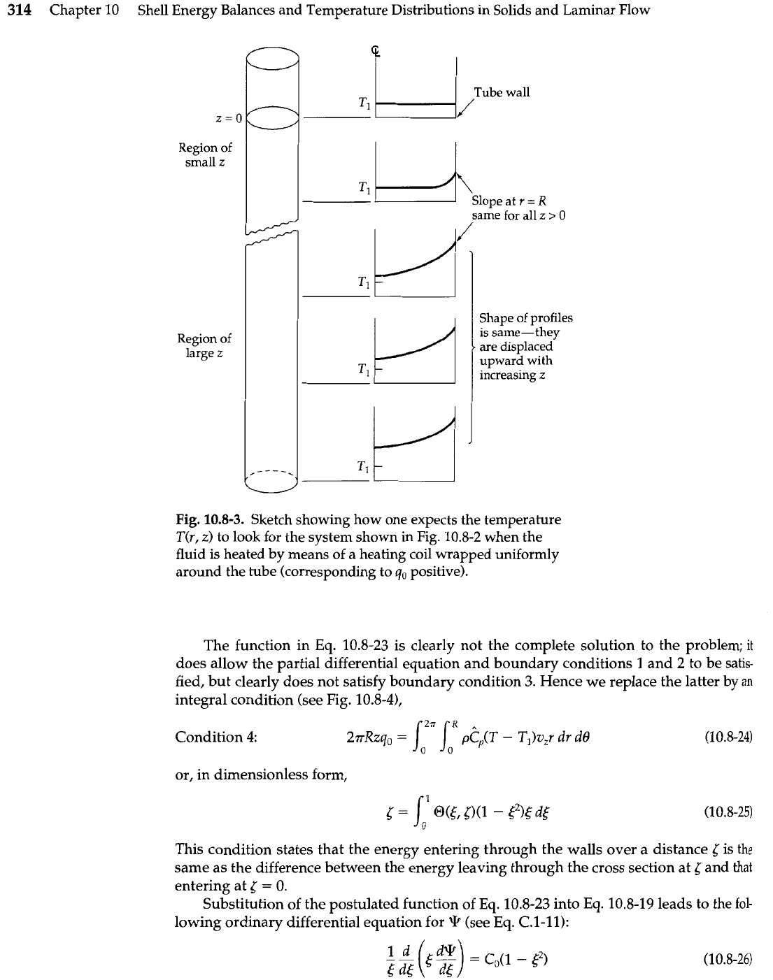
It is, however, instructive to obtain the asymptotic solution to Eq. 10.8-19 for large
5.
After the fluid is sufficiently far downstream from the beginning of the heated section,
one expects that the constant heat flux through the wall will result in a rise of the fluid
temperature that is linear in
5.
One further expects that the shape of the temperature pro-
files as a function of
,$
will ultimately not undergo further change with increasing (see
Fig. 10.8-3). Hence a solution of the following form seems reasonable for large 6:
in which
C,
is a constant to be determined presently.
%.
Siegel, E.
M.
Sparrow, and
T. M.
Hallman,
Appl.
Sci.
Research,
A7,386-392
(1958).
See
Example
12.2-1
for
the
complete solution and Example
12.2-2
for
the
asymptotic solution for small
5.
314
Chapter 10
Shell Energy Balances and Temperature Distributions in Solids and Laminar Flow
Tube
wall
z=o
Region of
small
z
Region
of
large
z
-
slope at
r
=
R
same for all
z
Shape of profiles
is same-they
are
displaced
upward with
increasing
z
Fig.
10.8-3.
Sketch showing how one expects the temperature
T(r,
z)
to look for the system shown in Fig. 10.8-2 when the
fluid is heated by means of a heating coil wrapped uniformly
around the tube (corresponding to
qo
positive).
The function in Eq. 10.8-23 is clearly not the complete solution to the problem;
it
does allow the partial differential equation and boundary conditions
1
and
2
to be satis-
fied, but clearly does not satisfy boundary condition 3. Hence we replace the latter by
an
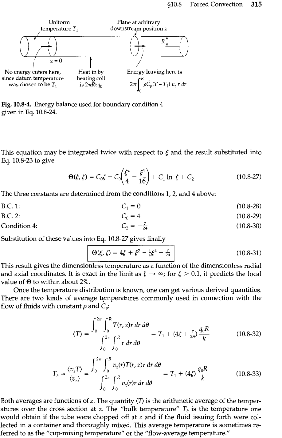
integral condition (see Fig. 10.8-41,
Condition
4:
21~Xzq~
=
/021
loR
-
T,)u,r dr
dB
(1
0.8-24)
or, in dimensionless form,
This condition states that the energy entering through the walls over a distance
5
is
the
same as the difference between the energy leaving through the cross section at
5
and that
entering at
5
=
0.
Substitution of the postulated function of Eq. 10.8-23 into Eq. 10.8-19 leads to the
fol-
lowing ordinary differential equation for
(see Eq. C.l-11):
s10.8
Forced Convection
315
Uniform
Plane at arbitrary
temperature
TI
downstream position
z
No energy enters here, ~eat'in by Energy leaving here is
since datum temperature heating coil
was chosen to be
TI
is
2rRzqO
Fig.
10.8-4.
Energy balance used for boundary condition 4
given in
Eq.
10.8-24.
This equation may be integrated twice with respect to
5
and the result substituted into
Eq.
10.8-23 to give
The three constants are determined from the conditions 1,2, and
4
above:
B.C. 1:
B.C. 2:
Condition
4:
Substitution of these values into
Eq.
10.8-27 gives finally
Both averages are functions of
z.
The quantity
(T)
is the arithmetic average of the temper-
atures over the cross section at
z.
The "bulk temperature"
Tb
is the temperature one
would obtain if the tube were chopped off at
z
and if the fluid issuing forth were col-
lected in a container and thoroughly mixed. This average temperature is sometimes re-
ferred to as the "cup-mixing temperature" or the "flow-average temperature."
O(&[)
=
45
+
3
-
at4
-
5
(10.8-31)
This result gives the dimensionless temperature as a function of the dimensionless radial
and axial coordinates. It is exact in the limit as
5
+
m;
for
5
>
0.1, it predicts the local
value of O to within about
2%.
Once the temperature distribution is known, one can get various derived quantities.
There are two kinds of average t$mperatures commonly used in connection with the
flow of fluids with constant
p
and
C,:
316
Chapter 10
Shell Energy Balances and Temperature Distributions in Solids and Laminar Flow
Now let us evaluate the local heat transfer driving force,
To
-
Tb, which is the differ-
ence between the wall and bulk temperatures at a distance
z
down the tube:
where
D
is the tube diameter. We may now rearrange this result in the form of a dimen-
sionless wall heat flux
which, in Chapter 14, will be identified as a
Nusselt
number.
Before leaving this section, we point out that the dimensionless axial coordinate
l
in-
troduced above may be rewritten in the following way:
Here
D
is the tube diameter, Re is the Reynolds number used in Part I, and Pr and
Pi.
are
the Prandtl and Pkclet numbers introduced in Chapter
9.
We shall find in Chapter 11 that
the Reynolds and Prandtl numbers can be expected to appear in forced convection
prob-
lems. This point will be reinforced in Chapter
14
in connection with correlations for heat
transfer coefficients.
510.9
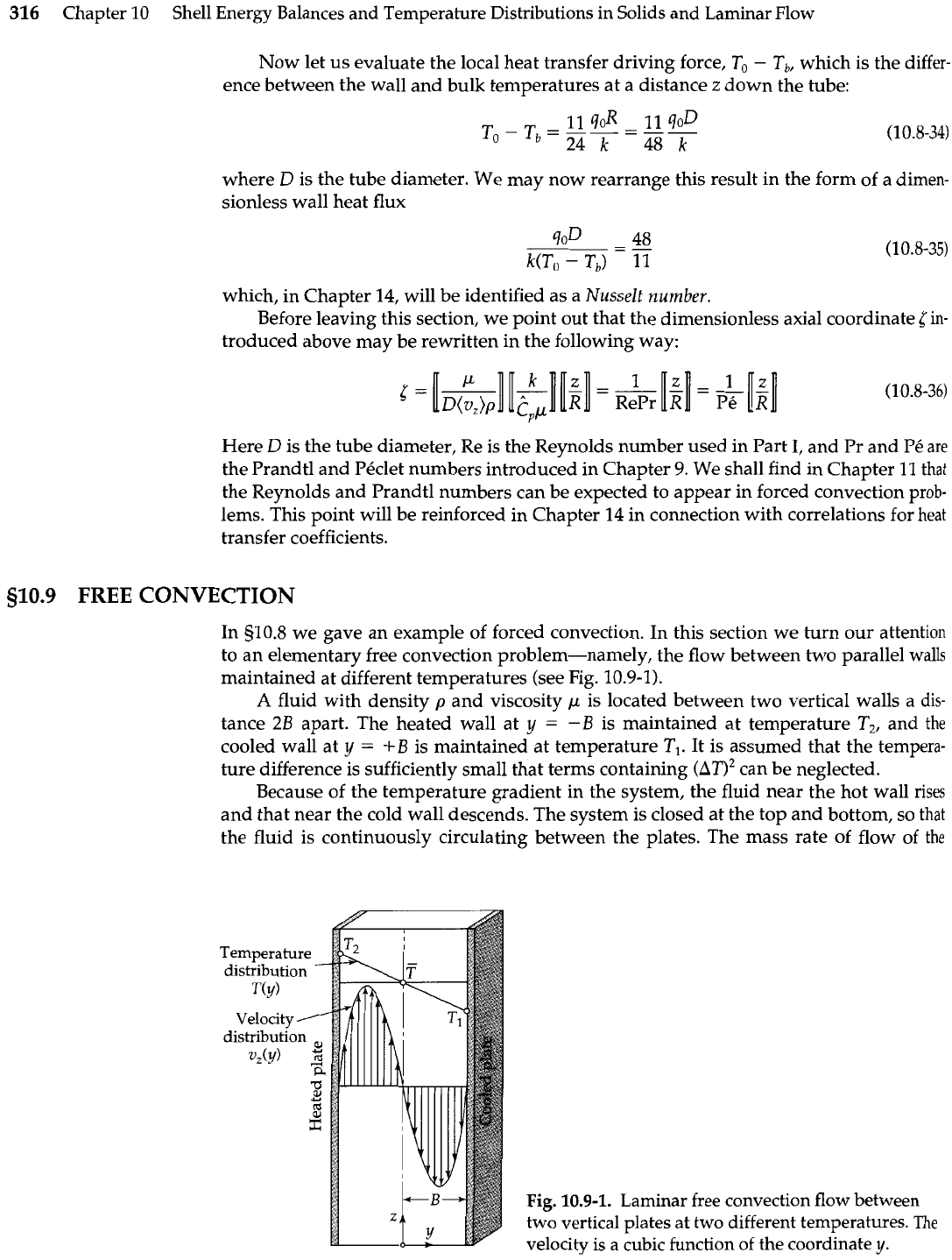
FREE
CONVECTION
In 510.8 we gave an example of forced convection. In this section we turn our attention
to an elementary free convection problem-namely, the flow between two parallel walls
maintained at different temperatures (see Fig. 10.9-1).
A
fluid with density
p
and viscosity
p
is located between two vertical walls
a
dis-
tance
2B
apart. The heated wall at
y
=
-B
is maintained at temperature
T,,
and the
cooled wall at
y
=
+
B
is maintained at temperature
TI.
It is assumed that the tempera-
ture difference is sufficiently small that terms containing
(An2
can be neglected.
Because of the temperature gradient in the system, the fluid near the hot wall rises
and that near the cold wall descends. The system is closed at the top and bottom,
so
that
the fluid is continuously circulating between the plates. The mass rate of flow of
the
Fig.
10.9-1.
Laminar free convection flow between
two vertical plates at two different temperatures.
The
velocity is a cubic function of the coordinate
y.
