Bichop R.H. (Ed.) Mechatronic Systems, Sensors, and Actuators: Fundamentals and Modeling
Подождите немного. Документ загружается.


20-104 Mechatronic Systems, Sensors, and Actuators
Active Stereoscopic
Due to the computationally intensive complexities and associated resources required for establishing
correspondence, passive stereoscopic methods were initially limited in practical embodiments to very
simple scenes (Blais et al., 1988). One way around these problems is to employ an active source in
conjunction with a pair of stereo cameras. This active illumination greatly improves system performance
when viewing scenes with limited contrast. Identification of the light spot becomes a trivial matter; a
video frame representing a scene illuminated by the source is subtracted from a subsequent frame of the
same image with the light source deactivated. Simple thresholding of the resultant difference image
quickly isolates the region of active illumination. This process is performed in rapid sequence for both
cameras, and the lateral displacement of the centroid of the spot is then determined.
Alignment between the source and cameras is not critical in active stereoscopic ranging systems; in
fact, the source does not even have to be located on board the robot. For example, Kilough and Hamel
(1989) describe two innovative configurations using external sources for use with the robot HERMIES
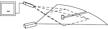
IIB, built at Oak Ridge National Laboratory. A pair of wide-angle black-and-white CCD cameras are
mounted on a pan-and-tilt mechanism atop the robot’s head, as shown in Figure 20.83. Analog video
outputs from the cameras are digitized by a frame grabber into a pair of 512 by 384-pixel arrays, with
offboard image processing performed by a Hypercube at a scaled-down resolution of 256 by 256. The
initial application of the vision system was to provide control of a pair of robotic arms (from the Heathkit
HERO-1 robot) employed on HERMIES.
To accomplish this task, a near-infrared LED is attached to the end of the HERO-1 arm near the
manipulator and oriented so as to be visible within the field of view of the stereo camera pair. A sequence
of images is then taken by each camera, with the LED first on and then off. The off representations are
subtracted from the on representations, leaving a pair of difference images, each comprised of a single
bright dot representing the location of the LED. The centroids of the dots are calculated to precisely
FIGURE 20.83 HERMIES IIB employed an active stereoscopic ranging system with an external laser source that
could be used to designate objects of interest in the video image. (Courtesy Oak Ridge National Laboratory.)
9258_C020_Sect_7-9.fm Page 104 Tuesday, October 9, 2007 9:09 PM
Sensors 20-105
determine their respective coordinates in the difference-image arrays. A range vector to the LED can
then be easily calculated, based on the lateral separation of the dots as perceived by the two cameras.
This technique establishes the actual location of the manipulator in the reference frame of the robot.
Experimental results indicated a 2-in. accuracy with a 0.2-in. repeatability at a distance of approximately
2 ft (Kilough and Hamel, 1989).
A near-infrared solid-state laser mounted on a remote tripod was then used by the operator to designate
a target of interest within the video image of one of the cameras. The same technique described above
was repeated, only this time the imaging system toggled the laser power on and off. A subsequent
differencing operation enabled calculation of a range vector to the target, also in the robot’s reference
frame. The difference in location of the gripper and the target object could then be used to effect both
platform and arm motion. The imaging processes would alternate in near-real-time for the gripper and
the target, enabling the HERMIES robot to drive over and grasp a randomly designated object under
continuous closed-loop control.
Structured Light
Ranging systems that employ structured light are a further refined case of active triangulation. A pattern of
light (either a line, a series of spots, or a grid pattern) is projected onto the object surface while the camera
observes the pattern from its offset vantage point. Range information manifests itself in the distortions
visible in the projected pattern due to variations in the depth of the scene. The use of these special lighting
effects tends to reduce the computational complexity and improve the reliability of three-dimensional
object analysis (Jarvis, 1983b; Vuylsteke et al., 1990). The technique is commonly used for rapid extraction
of limited quantities of visual information of moving objects (Kent, 1985), and thus lends itself well to
collision avoidance applications. Besl (1988) provides a good overview of structured-light illumination
techniques, while Vuylsteke et al. (1990) classify the various reported implementations according to the
following characteristics:
•
The number and type of sensors
•
The type of optics (i.e., spherical or cylindrical lens, mirrors, multiple apertures)
•
The dimensionality of the illumination (i.e., point or line)
•
Degrees of freedom associated with scanning mechanism (i.e., zero, one, or two)
•
Whether or not the scan position is specified (i.e., the instantaneous scanning parameters are not
needed if a redundant sensor arrangement is incorporated)
The most common structured-light configuration entails projecting a line of light onto a scene, originally
introduced by P. Will and K. Pennington of IBM Research Division Headquarters, Yorktown Heights,
NY (Schwartz, undated). Their system created a plane of light by passing a collimated incandescent
source through a slit, thus projecting a line across the scene of interest. (More recent systems create the
same effect by passing a laser beam through a cylindrical lens or by rapidly scanning the beam in one
dimension.) Where the line intersects an object, the camera view will show displacements in the light
stripe that are proportional to the depth of the scene. In the example depicted in Figure 20.84, the lower
the reflected illumination appears in the video image, the closer the target object is to the laser source.
The exact relationship between stripe displacement and range is dependent on the length of the baseline
FIGURE 20.84 A common structured-light configuration used on robotic vehicles projects a horizontal line of
illumination onto the scene of interest and detects any target reflections in the image of a downward-looking CCD
array.
TV Image
Laser
Camera
9258_C020_Sect_7-9.fm Page 105 Tuesday, October 9, 2007 9:09 PM
20-106 Mechatronic Systems, Sensors, and Actuators
between the source and the detector. Like any triangulation system, when the baseline separation
increases, the accuracy of the sensor increases, but the missing parts problem worsens.
Three-dimensional range information for an entire scene can be obtained in relatively simple fashion
through striped lighting techniques. By assembling a series of closely spaced two-dimensional contours,
a three-dimensional description of a region within the camera’s field of view can be constructed. The
third dimension is typically provided by scanning the laser plane across the scene. Compared to single-
point triangulation, striped lighting generally requires less time to digitize a surface, with fewer moving
parts because of the need to mechanically scan only in one direction. The drawback to this concept is
that range extraction is time consuming and difficult due to the necessity of storing and analyzing many
frames.
An alternative structured-light approach for three-dimensional applications involves projecting a
rectangular grid of high-contrast light points or lines onto a surface. Variations in depth cause the grid
pattern to distort, providing a means for range extraction. The extent of the distortion is ascertained by
comparing the displaced grid with the original projected patterns as follows (LeMoigue & Waxman, 1984):
•
Identify the intersection points of the distorted grid image.
•
Label these intersections according to the coordinate system established for the projected pattern.
•
Compute the disparities between the intersection points and/or lines of the two grids.
•
Convert the displacements to range information.
The comparison process requires correspondence between points on the image and the original pattern,
which can be troublesome. By correlating the image grid points to the projected grid points, this
problem can be somewhat alleviated. A critical design parameter is the thickness of the lines that make
up the grid and the spacing between these lines. Excessively thin lines will break up in busy scenes,
causing discontinuities that adversely affect the intersection points labeling process. Thicker lines will
produce less observed grid distortion resulting in reduced range accuracy (LeMoigue and Waxman,
1984). The sensor’s intended domain of operation will determine the density of points required for
adequate scene interpretation and resolution.
Magnetic Position Measurement Systems
Magnetic tracking uses a source element radiating a magnetic field (three axes) and a small sensor (three
axes) that reports its position and orientation with respect to the source. Competing systems provide
various multi-source, multi-sensor systems that will track a number of points at up to 100 Hz in ranges
from 3 to 20 ft (Polhemus Incorporated, and Ascension Technologies). They are generally accurate to
better than 0.1 in. in position and 0.1° in rotation. Magnetic systems do not rely on line-of-sight from
source to object, as do optical and acoustic systems, but metallic objects in the environment will distort
the magnetic field, giving erroneous readings. They require cable attachment to a central device (as do
LEDs and acoustic systems). Current technology is quite robust and widely used for single or double
hand-tracking, head-mounted devices, biomechanical analysis, graphics (digitization in 3D), stereotaxic
localization, etc.
Magnetic field sources can be AC or DC. DC sources may emit pulses rather than continuous radiation
in order to minimize interference from other magnetic sources. Using pulsed systems allows measurement
of existing magnetic fields in the environment during the inactive period. Knowledge of these magnetic
fields external to the system is used to improve accuracy and to overcome sensitivity to metals.
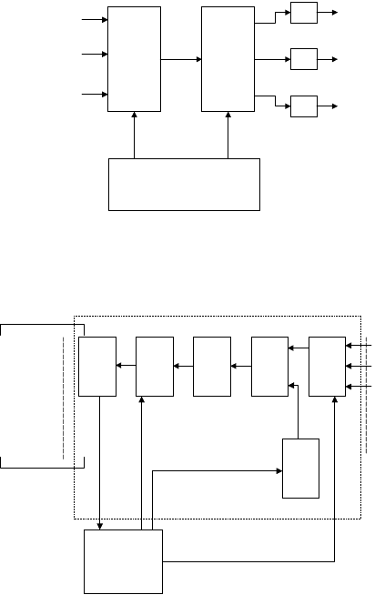
Figure 20.85 shows a typical transmitter-drive electronics (courtesy of Ascension Technologies). It
provides DC current pulses to each antenna of the transmitter, one antenna at a time. The transmitter
consists of a core about which the X, Y, and Z antennae are wound. While a given transmitter antenna
is activated with current, readings are taken from all three antennae of the sensor. Initially the transmitter
is shut off so that the sensor can measure the x, y, and z components of the earth’s magnetic field. During
operation, the computer sends to the digital-to-analog (D/A) converter a number that represents the
amplitude of the current pulse to be sent to the selected transmitter antenna. The D/A converter converts
9258_C020_Sect_7-9.fm Page 106 Tuesday, October 9, 2007 9:09 PM
Sensors 20-107
this amplitude to an analog control voltage. This control voltage goes to the multiplexer (MUX), which
connects it to the X, Y, or Z transmitter current source.
The sensor consists of three orthogonal antennae sensitive to DC magnetic fields. Many technologies
can be used to implement the DC sensor. The Flock (Ascension Technologies) uses a three-axis fluxgate
magnetometer. The output from the sensor goes to the signal processing electronics. As detailed in
Figure 20.86, the sensor signal processing electronics consists of a multiplexer (MUX), which, on command
from the computer, switches the desired X, Y, or Z sensor antenna signal, one at a time, to the differential
amplifier (DIFF). The differential amplifier subtracts from this antenna signal the previously measured
component of the earth’s magnetic field. It outputs only that part of the received signal that is due to the
transmitted field. The output from the differential amplifier is then filtered to remove noise and amplified.
The analog-to-digital converter converts the DC signal to a digital format that can be read by the computer.
20.7.1.3 Other Distance Measuring Methods
The following methods are used to measure displacement, and thus can be used to infer distance travelled
for certain applications.
Odometry
This is one of many methods to measure position and it is an indirect method of determining range.
Range is determined by measuring the rotation of a wheel as it traverses from the reference to the target
location. Wheel rotation is measured using angular encoders that may be digital or analog in nature.
FIGURE 20.85 Magnetic positioning system: transmitting circuit. (Courtesy of Ascension Technologies.)
FIGURE 20.86 Magnetic positioning system: receiving circuit. (Courtesy of Ascension Technologies.)
X
Y
Z
D/A
MUX
Transmitter
axes
Current
sources
CPU
SENSOR
AXES
SIGNALS
MUX
AMP A/D FILTER
+
–
DIFF
D/A
X
Y
Z
COMPUTER
9258_C020_Sect_7-9.fm Page 107 Tuesday, October 9, 2007 9:09 PM
20-108 Mechatronic Systems, Sensors, and Actuators
Angular Optical Encoders
These devices encompass a light source, optics to shape and guide the light, a coded wheel with transparent
and opaque sections, and a light detector array. There are two types of optical encoders: incremental and
absolute.
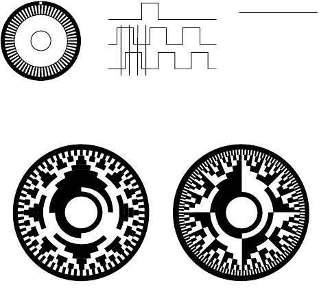
Incremental Angular Optical Encoders. A schematic is shown in Figure 20.87. The wheel is opaque except
for the slots along the circumference. Two rows of slots displaced by a 90° phase are used to determine
rotation and direction. As the wheel rotates, two pulse chains 90° out of phase with each other are
generated (Channels A and B). Distance is determined by counting the number of pulses (and quarter
pulses for increased resolution) from the initial arbitrary zero position. The reference is lost when power
is interrupted. The direction of motion is defined by determining which pulse chain leads the other.
An index pulse that appears once per revolution is also usually available (Channel Z). The resolution
depends upon the number of slots around the circumference. Larger wheels can accommodate higher
resolution. The total distance traveled depends upon the system used to count pulses. Since pulse counting
is done outside the sensor, distances in the meters may be measured.
Decoding of the pulses (Channels A, B, and Z) to obtain angular displacement is done using specialized
chips (Hewlett Packard makes a family of chips), or full-fledged integrated circuit boards. Data acquisition
boards with counters may also be programmed to decode range from these sensors.
Commercially available units have a maximum operating speed of about 6000 rpm, maximum counts
per revolution of about 360,000, a maximum resolution of 0.001°, and a frequency response of up to
150 kHz.
Absolute Angular Optical Encoders.
These encoders have a wheel which is coded in such a way that each
angular slot represents a number of bits that may be either
on
(transparent) or
off
(opaque) (Figure 20.88).
Therefore, the angular position of the wheel has an absolute value given by the code of the angular slot
currently aligned with the optics. Its position is known even after turning the power
off
and
on
again.
When the optics crosses the line between two slots, the pattern changes to indicate an increment of one
unit. However, the position is uncertain if the wheel stops with the optics right on the line. To decrease
this uncertainty, the patterns are defined according to the Grey Code. In this coding scheme, only one
bit of the pattern changes from one slot to the next. Thus, the uncertainty is minimized to one unit.
FIGURE 20.87 Optical incremental angular encoder.
FIGURE 20.88 Absolute optical encoder.
High Low
High High
HighLow
Low Low
Ch A
Ch B
State
B
412
3
S
4
A
I
S
3
S
2
S
1
AB
9258_C020_Sect_7-9.fm Page 108 Tuesday, October 9, 2007 9:09 PM
Sensors 20-109
These sensors are suitable to measure small ranges, in the order of hundreds of millimeters. Larger wheels
can accommodate more slots and more bits per slot. Commercial units of 11 bits are available, with a
resolution of ±1/2 of the least significant bit, and a frequency response of 100 K 11-bit words per second.
Linear Optical Encoders. These are the same as angular encoders, except that instead of a coded wheel,
they have a coded bar and a slider that carries the optical and electronic components. Distance is measured
along the bar. In commercial units, the maximum measuring distance is about 2.150 m, the maximum
resolution 0.08
µ
m, and the maximum operating speed 508 mm/s.
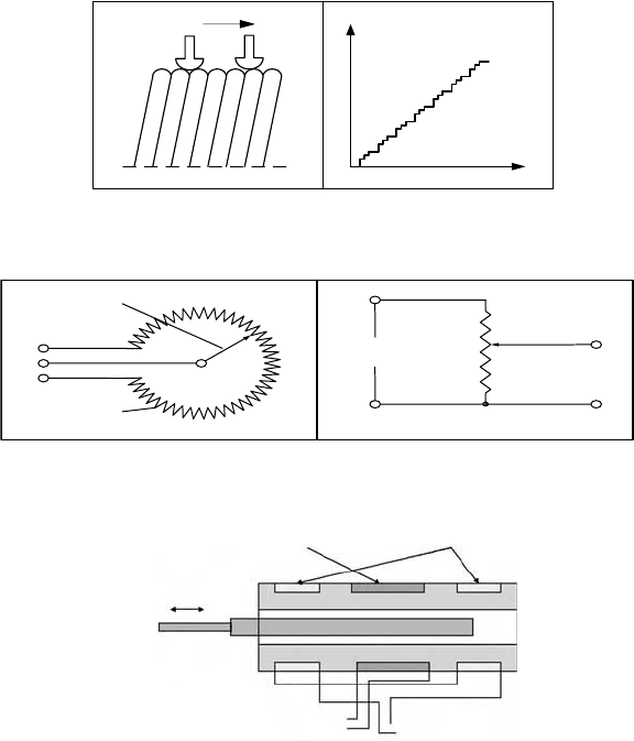
Potentiometers
Potentiometers are variable electrical resistance transducers. They consist of a winding and a sliding
contact. As the sliding contact moves along the winding, the resistance changes in linear relationship
with the distance from one end of the potentiometer (Figure 20.89). The variable resistance is wired as
a voltage divider so that the output voltage is proportional to the distance traveled by the wiper
(Figure 20.90). The resolution is defined by the number of turns per unit distance, and loading effects
of the voltage divider circuit should be considered.
Linear Variable Differential Transformers
The linear variable differential transformer (LVDT) generates an AC signal whose magnitude is related
to the displacement of a moving core (Figure 20.91). As the core changes position with respect to the
coils, it changes the magnetic field, and thence the voltage amplitude in the secondary coil.
FIGURE 20.89 Potentiometer: principle of operation.
FIGURE 20.90 Potentiometer: circuit representation.
FIGURE 20.91 Linear variable differential transformer.
Potentiometer wires
(a)
Wiper
Displacement
(b)
Output
voltage
(a)
1
2
3
Movable
slider
Resistance
element
(b)
3
3
Reference
soltage
1
Variable
voltage
output
2
Secondary coils
Measured output
volta
g
e
Measured
displacement
Constant
AC volta
g
e
Primary coil
9258_C020_Sect_7-9.fm Page 109 Tuesday, October 9, 2007 9:09 PM
20-110 Mechatronic Systems, Sensors, and Actuators
LVDT resolution depends on the instruments used to measure voltage. 25-
µ
m resolution can
be achieved. Stationary (low frequency) signals may be measured using an AC meter. High frequency
signals require specialized electronics for demodulation or a data acquisition system to process the signal
using a PC.
A rotary variable differential transformer (RVDT) operates under the same principle as the LVDT and
is available with a range of approximately ±40°.
20.7.2 Proximity Sensors
Proximity sensors, used to determine the presence (as opposed to actual range) of nearby objects, were
developed to extend the sensing range beyond that afforded by direct-contact tactile or haptic sensors.
Recent advances in electronic technology have significantly improved performance and reliability, thereby
increasing the number of possible applications. As a result, many industrial installations that historically
have used mechanical limit switches can now choose from a variety of alternative noncontact devices for
their close (between a fraction of an inch and a few inches) sensing needs. Such proximity sensors are
classified into several types in accordance with the specific properties used to initiate a switching action:
•
Magnetic
•
Inductive
•
Ultrasonic
•
Microwave
•
Optical
•
Capacitive
The reliability characteristics displayed by these sensors make them well suited for operation in harsh
or otherwise adverse environments, while providing high-speed response and long service lives. Instru-
ments can be designed to withstand significant shock and vibration, with some capable of handling forces
over 30,000 Gs and pressures of nearly 20,000 psi (Hall, 1984). Burreson (1989) and Peale (1992) discuss
advantages and tradeoffs associated with proximity sensor selection for applications in challenging and
severe environments. In addition, proximity devices are valuable when detecting objects moving at high
speed, when physical contact may cause damage, or when differentiation between metallic and nonme-
tallic items is required. Ball (1986), Johnson (1987), and Wojcik (1994) provide general overviews of
various alternative proximity sensor types with suggested guidelines for selection.
20.7.2.1 Magnetic Proximity Sensors
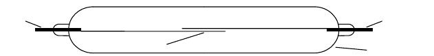
The simplest form of magnetic proximity sensor is the magnetic reed switch, schematically illustrated in
Figure 20.92. A pair of low-reluctance ferromagnetic reeds are cantilevered from opposite ends of a
hermetically sealed tube, arranged such that their tips overlap slightly without touching. The extreme
ends of the reeds assume opposite magnetic polarities when exposed to an external magnetic flux, and
the subsequent attractive force across the gap pulls the flexible reed elements together to make electrical
contact (Hamlin, 1988).
Available in both normally open and normally closed configurations, these inexpensive and robust devices
are commonly employed as door- and window-closure sensors in security applications. Some problems
FIGURE 20.92 The hermetically sealed magnetic reed switch, shown here with normally open contacts, is filled with
inert gas and impervious to dust and corrosion.
External
connection
Glass envelope
Contacts
External
connection
9258_C020_Sect_7-9.fm Page 110 Tuesday, October 9, 2007 9:09 PM
Sensors 20-111
can be encountered with this type of sensor due to contact bounce, structural vibration, and pitting of
the mating surfaces in the case of inductive or capacitive loads (Burreson, 1989), prompting most designers
to opt instead for the more reliable solid-state Hall-effect magnetic sensor.
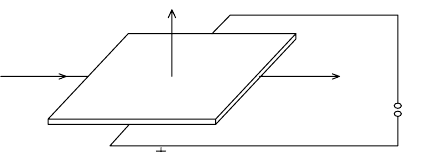
The Hall effect, as it has come to be known, was discovered by E.H. Hall in 1879. Hall noted a very
small voltage was generated in the transverse direction across a conductor carrying a current in the
presence of an external magnetic field (Figure 20.93), in accordance with the following equation (White,
1988):
where
V
h
= Hall voltage,
R
h
= material-dependent Hall coefficient,
I = current in amps,
B = magnetic flux density (perpendicular to I) in Gauss, and
t = element thickness in centimeters.
It was not until the advent of semiconductor technology (heralded by the invention of the transistor
in 1948) that this important observation could be put to any practical use. Even so, early silicon imple-
mentations were plagued by a number of shortcomings that slowed popular acceptance, including high
cost, temperature instabilities, and otherwise poor reliability (McDermott, 1969). Subsequent advances
in integrated circuit technology (i.e., monolithic designs, new materials, and internal temperature com-
pensation) have significantly improved both stability and sensitivity. With a 100-mA current flow through
indium arsenide (InAs), for example, an output voltage of 60 mV can be generated with a flux density
(B) of 10 kG (Hines, 1992). Large-volume applications in the automotive industry (such as distributor
timing in electronic ignition systems) helped push the technology into the forefront in the late 1970s
(White, 1988). Potential robotic utilization includes position and speed sensing, motor commutation
(Manolis, 1993), guidepath following, and magnetic compasses.
The linear relationship of output voltage to transverse magnetic field intensity is an important feature
contributing to the popularity of the modern Hall-effect sensor. To improve stability, linear Hall-effect
sensors are generally packaged with an integral voltage regulator and output amplifier. The output voltage
V
o
fluctuates above and below a zero-field equilibrium position (usually half the power supply voltage
V
cc
), with the magnitude and direction of the offset determined by the field strength and polarity,
respectively (White, 1988). (Note also that any deviation in field direction away from the perpendicular
will also affect the magnitude of the voltage swing.) Frequency responses over 100 kHz are easily achieved
(Wood, 1986).
The addition of a Schmitt-trigger threshold detector and an appropriate output driver transforms the
linear Hall-effect sensor into a digital Hall-effect switch. Most commercially available devices employ
transistor drivers that provide an open-circuit output in the absence of a magnetic field (Wood, 1986).
FIGURE 20.93 In 1879, E.H. Hall discovered a small transverse voltage was generated across a current-carrying
conductor in the presence of a static magnetic field, a phenomenon now known as the Hall effect. (Adapted from
Lenz, 1990.)
Output
voltage
Magnetic
field
Current
flow
I
V
h
R
h
IB
t
-----------
=
9258_C020_Sect_7-9.fm Page 111 Tuesday, October 9, 2007 9:09 PM
20-112 Mechatronic Systems, Sensors, and Actuators
The detector trip point is set to some nominal value above the zero-field equilibrium voltage, and when
this threshold is exceeded, the output driver toggles to the on state (source or sink, depending on whether
PNP or NPN transistor drivers are employed). A major significance of this design approach is the resulting
insensitivity of the Hall-effect switch to reverse magnetic polarity. While the mere approach of the south
pole of a permanent magnet will activate the device, even direct contact by the north pole will have no
effect on switching action, as the amplified output voltage actually falls further away from the Schmitt-
trigger setpoint. Switching response times are very rapid, typically in the 400-ns range (Wood, 1986).
20.7.2.2 Inductive Proximity Sensors
Inductive proximity switches are today the most commonly employed industrial sensors (Moldoveanu,
1993) for detection of ferrous and nonferrous metal objects (i.e., steel, brass, aluminum, copper) over
short distances. Cylindrical configurations as small as 4 mm in diameter have been available for over a
decade (Smith, 1985). Because of the inherent ability to sense through nonmetallic materials, these sensors
can be coated, potted, or otherwise sealed, permitting operation in contaminated work areas, or even
submerged in fluids. Frequency responses up to 10 kHz can typically be achieved (Carr, 1987).
Inductive proximity sensors generate an oscillatory RF field (i.e., 100 kHz to 1 MHz) around a coil of
wire typically wound around a ferrite core. When a metallic object enters the defined field projecting
from the sensor face, eddy currents are induced in the target surface. These eddy currents produce a
secondary magnetic field that interacts with field of the probe, thereby loading the probe oscillator. The
effective impedance of the probe coil changes, resulting in an oscillator frequency shift (or amplitude
change) that is converted into an output signal proportional to the sensed gap between probe and target.
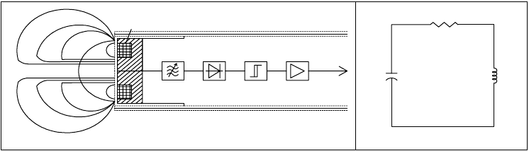
A block diagram of a typical inductive proximity sensor is depicted in Figure 20.94(a). The oscillator
comprises an active device (i.e., a transistor or IC) and the sensor probe coil itself. An equivalent circuit
(Figure 20.94(b)) representing this configuration is presented by Carr (1987), wherein the probe coil is
modeled as an inductor L
p
with a series resistor R
p
, and the connecting cable between the coil and the
active element shown as a capacitance C. In the case of a typical Collpitts oscillator, the probe-cable
combination is part of a resonant frequency tank circuit.
As a conductive target enters the field, the effects of the resistive component R
p
dominate, and resistive
losses of the tank circuit increase, loading (i.e., damping) the oscillator (Carr, 1987). As the gap becomes
smaller, the amplitude of the oscillator output continues to decrease, until a point is reached where
oscillation can no longer be sustained. This effect gives rise to the special nomenclature of an eddy-
current-killed oscillator (ECKO) for this type of configuration. Sensing gaps smaller than this minimum
threshold (typically from 0.005 to 0.020 in.) are not quantified in terms of an oscillator amplitude that
correlates with range, and thus constitute a dead-band region for which no analog output is available.
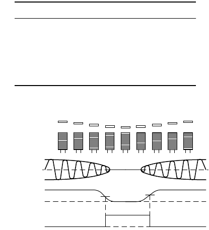
Monitoring the oscillator output amplitude with an internal threshold detector creates an
inductive
proximity switch
with a digital
on/off
output (Figure 20.95). As the metal target approaches the sensor face,
the oscillator output voltage falls off as shown, eventually dropping below a preset
trigger level
, whereupon
the threshold comparator toggles from an
off
state to an
on
state. Increasing the gap distance causes the
FIGURE 20.94 (a) Block diagram of a typical ECKO-type inductive proximity sensor. (Adapted from Smith, 1985.),
and (b) equivalent oscillator circuit. (Adapted from Carr, 1987.)
Oscillator coil
Response field
Oscillator
(b)(a)
C
Oscillator
L
p
R
p
Epoxied resin
Demodulator
Amplifier
Trigger
Threaded cylinder
Equivalent
circuit
9258_C020_Sect_7-9.fm Page 112 Tuesday, October 9, 2007 9:09 PM
Sensors 20-113
voltage to again rise, and the output switches
off
as the
release level
is exceeded. The intentional small
difference between the trigger level and the release level, termed
hysteresis
, prevents output instabilities
near the detection threshold. Typical hysteresis values (in terms of gap distance) range from 3% to 20%
of the maximum effective range (Damuck & Perrotti, 1993).
Effective sensing range is approximately equal to the diameter of the sensing coil (Koenigsburg, 1982)
and is influenced by target material, size, and shape. The industry standard target (for which the nominal
sensing distance is specified) is a 1-mm-thick square of mild steel of the same size as the diameter of the
sensor, or three times the nominal sensing distance, whichever is greater (Flueckiger, 1992). For ferrous
metals, increased target thickness has a negligible effect (Damuck & Perrotti, 1993). More conductive
nonferrous target materials such as copper and aluminum result in reduced detection range, as illustrated
in Table 20.4. For such nonferrous metals, greater sensing distances (roughly equivalent to that of steel)
can be achieved with thin-foil targets having a thickness less than their internal field attenuation distance
(Smith, 1985). This phenomenon is known as the foil effect and results from the full RF field penetration
setting up additional surface eddy currents on the reverse side of the target (Damuck & Perrotti, 1993).
There are two basic types of inductive proximity sensors: (1) shielded (Figure 20.96a) and (2) unshielded
(Figure 20.96b). If an unshielded device is mounted in a metal surface, the close proximity of the
surrounding metal will effectively saturate the sensor and preclude operation altogether (Swanson, 1985).
To overcome this problem, the shielded configuration incorporates a coaxial metal ring surrounding the
core, thus focusing the field to the front and effectively precluding lateral detection (Flueckiger, 1992).
There is an associated penalty in maximum effective range, as shielded sensors can only detect out to
about half the distance of an unshielded device of equivalent diameter (Swanson, 1985).
Mutual interference between inductive proximity sensors operating at the same frequency can result if
the units are installed with a lateral spacing of less than twice the sensor diameter. This interference typically
manifests itself in the form of an unstable pulsing of the output signal, or reduced effective range, and is
most likely to occur in the situation where one sensor is undamped and the other is in the hysteresis range
(Smith, 1985). Half the recommended 2d lateral spacing is generally sufficient for elimination of mutual
TABLE 20.4 Nominal Sensing Ranges for Material
Other Than Mild Steel Must Be Adjusted Using the
Above Attenuation Factors
Material Attenuation Factor
Cast Iron 1.10
Mild Steel 1.00
Stainless Steel 0.70–0.90
Brass 0.45
Aluminum 0.40
Copper 0.35
Source: Smith, 1985.
FIGURE 20.95 A small difference between the trigger and release levels (hysteresis) eliminates output instability as
the target moves in and out of range. (Adapted from Moldoveanu, 1993.)
Magnitude of
oscillations
Binar
y
output
Output voltage
Off
Trigger level
Sensor
Metal target
Release level
On
Off
9258_C020_Sect_7-9.fm Page 113 Tuesday, October 9, 2007 9:09 PM