Bichop R.H. (Ed.) Mechatronic Systems, Sensors, and Actuators: Fundamentals and Modeling
Подождите немного. Документ загружается.


20-74 Mechatronic Systems, Sensors, and Actuators
definition for the discussion of temperature measuring techniques presented here. While this definition
may help us understand the concept of temperature, it does not help us assign a numerical value to
temperature or provide us with a convenient method for measuring temperature. The zeroth law of
thermodynamics, formulated in 1931 more than half a century after the first and second laws, lays the
foundation for all temperature measurement. It states that if two bodies are in thermal equilibrium with
a third body, they are also in thermal equilibrium with each other. By replacing the third body with a
thermometer, we can state that two bodies are in thermal equilibrium if both have the same temperature
reading even if they are not in contact.
The zeroth law does not enable the assignment of a numerical value for temperature. For that we must
refer to a standard scale of temperature. Two absolute temperature scales are defined such that the
temperature at zero corresponds to the theoretical state of no molecular movement of the substance. This
leads to the Kelvin scale for the SI system and the Rankine scale for the English system. There are other
two-point scales derived by identifying two arbitrary defining points for temperature. These are usually
defined as the temperature at which a pure substance undergoes a change in phase. Familiar defining
points are the freezing and boiling point of water for 0°C and 100°C, respectively. A wide range of
such phase changes, many of them triple points where all three phases are in equilibrium, have been
accepted as the defining points of the International Practical Temperature Scale of 1990 (ITS
90
) shown
in Table 20.4. These can be used directly as calibration points for temperature monitors as long as the
substances are pure and the other conditions, such as pressure, which are included in the defining points
are met. Within the ITS
90
guidelines are standard means of interpolating temperatures between the
defined points. For example, platinum resistors are used in the range from 13.8 to 1235 K. The resistance
is fitted to the temperature through a higher-order polynomial that may be simplified for more limited
ranges between defined temperature points. The difference between a linear interpolation of resistance
between the defined points and the higher-order polynomial interpolation never exceeds 2 mK (Magnum
and Furukawa, 1990).
Another complication that is encountered in any discussion of temperature measurement is the fact
that temperature is an intrinsic rather than an extrinsic property. Thus, temperature can not be added,
subtracted, and divided in the same way that measured extrinsic properties such as length or voltage can
be manipulated.
Any property that changes predictably in response to temperature can be used in a temperature sensor.
The discussion of temperature measuring devices given here subdivides the devices based on the mea-
suring principle. Discussion will begin with a series of thermometers that rely upon the differential
expansion coefficients of the materials, be they solid, liquid, or gas. Mercury thermometers, perhaps the
most well known and widely used of all temperature measuring devices, belong to this category. We will
then move on to devices that rely upon phase change. Next we will discuss electrical temperature sensors
and transducers. Included in this category are thermocouples, RTDs, and thermistors, as well as integrated
TABLE 20.4 Fixed Points Used in ITS
90
∗
Triple point of hydrogen 13.8033 K
Triple point of neon 24.5561 K
Triple point of oxygen 54.3584 K
Triple point of argon 83.8058 K
Triple point of mercury 234.3156 K
Triple point of water 273.16 K
Melting point of gallium 302.9146 K
Freezing point of indium 429.7485 K
Freezing point of tin 505.078 K
Freezing point of zinc 692.677 K
Freezing point of aluminum 933.573 K
Freezing point of silver 1234.93 K
Freezing point of gold 1337.33 K
Freezing point of copper 1357.77 K
∗
Magnum (1990) includes the full definition of these points.
9258_C020_Sec_4-6.fm Page 74 Tuesday, October 9, 2007 9:09 PM
Sensors 20-75
circuit temperature sensors. The final category of temperature sensors will be noncontact sensors. A
separate discussion of temperature measurements on the microscale is provided at the end. Many of the
techniques discussed in the microscale section will be derivatives of those introduced earlier in the
discussion, but alterations, ranging from minor to quite major, must be made to enable small-scale and/or
quick response temperature measurements.
20.6.2 Thermometers That Rely Upon Differential Expansion Coefficients
Thermometers that rely upon differential expansion coefficients are by far the most common and familiar
direct reading temperature monitors. These thermometers can be divided into categories depending on
the state of the materials used. Each of these deserves a separate discussion.
20.6.2.1 Gas versus Solid
The gas bulb thermometer, which is used to determine absolute zero from extrapolation of the change
in pressure of a simple gas in a metal sphere with a change in temperature, is an example of a gas versus
solid thermometer. If the metal bulb had the same expansion coefficient as the fill gas, the pressure inside
would remain constant and it would not be a thermometer. Instead, the gas follows the ideal gas law,
which indicates that, at a constant volume, the pressure is linearly related to the temperature and the
vessel containing the gas changes linearly with the volumetric expansion coefficient of the metal making
up the bulb. The thermal expansion coefficient of the metal is usually ignored unless very precise
predictions of absolute zero are required.
While a large metal sphere with a pressure gage attached is not a very convenient means of measuring
temperature, except as a demonstration or research tool, the bulb can be made quite small and connected
via a small capillary tube to a remote pressure gage. In this miniaturized configuration the gas bulb
thermometer becomes a practical means of measuring temperature. As long as the device operates in the
ideal gas region, the pressure gage can be graduated to read temperature directly, since pressure is linearly
related to temperature.
Some major limitations on gas bulb thermometers are that the instrument should be calibrated
specifically for a particular installation since the length of the heated capillary, as well as the ambient
pressure and temperature at the pressure gage, will influence the accuracy of the device. These limitations
can be overcome at the expense of complication by using bimetallic elements in the pressure gage to
compensate for the temperature at that point or by having a parallel capillary with no bulb follow the
main capillary up to the point of measurement and have the parallel capillary equipped with a pressure
gage linked to subtract its effects from the main gage. Also, any damage that changes the volume of the
bulb, such as a dent, will shift the calibration. This style of instrument should not be confused with vapor
pressure thermometers that can take on an identical exterior form, but instead of being filled with an
ideal gas, they contain a two-phase fluid and the saturation pressure of the fluid is measured. This type
of temperature sensor is discussed in further detail in another section.
20.6.2.2 Liquid versus Solid
The common mercury and glass thermometer is an example of a liquid versus solid temperature sensor.
The thermal expansion of liquids, although not as great as gasses, is generally much greater than that of
solids and for many applications the expansion coefficient of the glass can be ignored. However, for
precision measurements, the expansion of the glass can introduce significant errors. There are two
common means of dealing with the glass expansion coefficient. Thermometers intended for reading the
temperature of a liquid bath might have a specified submergence depth indicated by a mark on the stem.
It is assumed that the rest of the thermometer is at standard lab conditions. This is not always a good
assumption, however, and a more precise way of handling the glass expansion coefficient compared to
that of mercury is to use a pair of total submergence thermometers. One measures the temperature of
the liquid and the other measures the temperature in the immediate vicinity of the exposed stem. A
simple stem correction formula supplied by the thermometer manufacturer can then be applied to
determine the temperature of the bath.
9258_C020_Sec_4-6.fm Page 75 Tuesday, October 9, 2007 9:09 PM
20-76 Mechatronic Systems, Sensors, and Actuators
The ratio of the volume of the bulb to the bore of the capillary determines the resolution of the
thermometer. The amount of liquid initially in the thermometer determines its range. The accuracy of the
bore and graduation markings determines its precision. The temperature read from a liquid-glass ther-
mometer is only valid if the liquid in the bore is continuous from the bulb to the point of reading.
Separations can be eliminated by either contracting the fluid entirely into the bulb or, in some cases, by
expanding it into a reservoir at the top of the thermometer. Mercury is useful from near its freezing
temperature (about −40°C) to around 500°C. The boiling point of mercury is only 357°C at standard
pressure, so mercury thermometers designed for very high temperatures must be pressurized with an
inert cover gas when sealed. Alcohol or other liquids can be used in place of mercury, but the accuracy
is generally not as great. The temperature range of alcohol extends from about −200°C to +250°C.
An alternative means of using the difference in expansion coefficients of liquids and solids to measure
temperature is to use a system filled completely with a liquid and to monitor the change in the volume
of the liquid by the position of a bourdon tube or bellows. If the volume-measuring element has a high
spring constant, the compressibility of the liquid might have to be considered (Doebelin, 1990). This
scheme has the same disadvantages as the gas bulb thermometer discussed above, as well as the same
compensation means for overcoming these disadvantages.
20.6.2.3 Gas, Liquid, and Solid
Some early thermometers consisted of a gas bulb connected to a sealed U-tube containing mercury or
another liquid. This, in effect, is really a gas pressure thermometer using a mercury manometer to indicate
pressure. To be accurate, the various coefficients of expansion of all three phases must be considered.
These instruments are rarely used where accuracy is important. The only example still widely used is a
style of minimum-maximum thermometer for ambient air measurements where a small metal fiber is
displaced in either leg of the manometer by the mercury. The fiber has enough friction in the tube and
is not wetted by the mercury so that it remains free in the glass tube after the mercury shifts. The indicator
on the gas bulb side stays at the minimum temperature while the indicator on the other leg stays at the
maximum temperature as the mercury recedes. Once the minimum and maximum temperatures are
observed, the fibers can be repositioned to the top of the two mercury columns by either centrifugal
force (slinging the whole thermometer) or with a magnet if iron fibers are used.
20.6.2.4 Solid versus Solid
Bimetallic thermometers consist of two metals with differing temperature expansion coefficients bonded
together. As the temperature varies from the temperature at which the metals were initially bonded, the
metals expand by differing amounts and the composite experiences a shearing force. The most common
means of monitoring the shearing is to allow the metal composite to bend in response to temperature
changes. The form of the composite can take on many configurations varying in complexity from a
simple leaf fixed at one end with a pointer on the other to a small helix fixed at one end and a turning
shaft at the other that is linked to a pointer, possibly through a gear train. The shaft is supported on fine
bearings with the pointer as much as a meter away from the bimetallic helix. Stick thermometers with
a dial at one end are an example of the latter.
Since the temperature variations produce a force, there must always be some gradated restoring force
applied to the bimetallic strip. The most common application is to use the bimetallic strip itself as a
restoring spring. The final position of the strip is a balance between the shear imposed by the differing
temperature coefficients and the spring constant of the strip. There are instances when bimetallic ther-
mometers are required to actuate a switch. In these cases the load imposed by the switch must be overcome
by the shear forces in the strip and the designer must consider it as an external load. The temperature
range of bimetallic thermometers is limited by the annealing temperature or phase transformation of
the metals. Bimetallics are thus mainly used well below 700°C, and they can be permanently damaged
if the metals change their properties or the bonding between the different metals fails. A common pair
of metals is a nickel steel, such as Invar with a very low thermal expansion coefficient, bonded to a brass
alloy with a high thermal expansion coefficient.
9258_C020_Sec_4-6.fm Page 76 Tuesday, October 9, 2007 9:09 PM
Sensors 20-77
20.6.3 Thermometers That Rely Upon Phase Changes
Phase transitions of pure substances at specified pressures are used in the ITS
90
to define several of the
temperature points. This concept of a phase change being a function of temperature, as well as pressure
and the type of material, can be exploited in several forms as a means of determining the temperature
of a system by observing either the phase change itself or the conditions at which the two phases are in
equilibrium. Several useful applications of this are discussed below.
20.6.3.1 Liquid to Gas
A common remote thermometer consists of a bulb containing a liquid-gas two-phase fluid connected
via a capillary tube to a pressure gage. As long as both phases are present, the pressure read on the gage
yields the saturation pressure of the fluid. This arrangement overcomes many of the disadvantages of
the gas versus solid thermometers with the same outward appearance described in section “Gas versus
Solid” above. By monitoring the saturation pressure, the indicated temperature is independent of the
temperature of the rest of the system and is insensitive to the actual volume of the bulb and capillary.
The fluid is typically an organic solvent such as ethane selected for the particular temperature range
desired. To keep the two-phase fluid entirely in the bulb, the pressure can be transmitted through the
capillary using a single-phase fluid such as oil. Few fluids have a linear saturation curve. Therefore, most
pressure gages have a notably nonlinear scale when graduated into units of temperature. Special compen-
sation springs within the pressure gage can be used to allow for a nearly linear temperature scale, but the
extra complication is rarely warranted.
The temperature range of liquid to gas thermometers is limited by the two phases of the fluid and
they are typically useful from −40°C to 300°C, although a single instrument rarely will operate over more
than about a 150°C span. If the saturation pressure of the fluid is very much greater than 100 kPa, a
simple pressure gage referenced to atmospheric pressure can be used. Otherwise best accuracy is obtained
using an absolute pressure gage. The volume of the bulb must be large compared to the change in volume
of the capillary and bourdon tube in the pressure gage so that both phases are always present in the bulb.
The size of the bulb keeps these thermometers from being used for point measurements.
20.6.3.2 Reversible Phase Change Thermostats
Fixed-point thermostats may be constructed based upon the phase change of a particular sensing element.
An example is used in mechanical ice-point references where the sudden expansion of water as it freezes
is sensed to cycle the cooling system to maintain a two-phase bath. The actual melting and freezing of
the ice maintains the reference temperature. Waxes of various melting points can be used in a similar
manner.
Another example is a magnetic switch held closed by a permanent magnet until the Curie temperature
is reached at which point the magnet loses its magnetism, or more properly, changes from a ferromagnetic
material to a paramagnetic material, and the switch opens. When the material cools, it regains its
ferromagnetism, which closes the heater switch. The magnetic material can be selected to have the
appropriate Curie temperature.
20.6.3.3 Fixed Temperature Indicators
Any substance that changes phase at a fixed temperature can be used as a temperature indicator. Numer-
ous examples exist, the most common being a crayon made of a wax with a defined melting point. A mark
is made on the object whose temperature needs to be monitored, and if the wax melts, its temperature
is higher than the crayon point. These fixed temperature indicators are generally irreversible and can
take on many forms in addition to crayons.
A variation that can be either reversible or irreversible is a paint containing suspended solids of the
wax or similar material that melts at the desired indication temperature. As long as the particles are
solid and scatter light, the paint appears opaque, but when they melt and turn into a liquid with a
refractive index close to that of the base paint, it appears clear. These indicators can be made in a series
of spots with varying temperature points to help monitor actual temperature attained rather than just
9258_C020_Sec_4-6.fm Page 77 Tuesday, October 9, 2007 9:09 PM
20-78 Mechatronic Systems, Sensors, and Actuators
a go, no-go indication. The spots can be made reversible for real-time indications or irreversible to
indicate the maximum temperature reached over the monitoring period, although the irreversible ones
are much more common than the reversible kind.
Although waxes are widely used, any material that has a distinct phase change at a defined temperature
can be used in such a monitor. Imaging techniques other than visual can also be used to determine the
phase change. One such application involves using gadolinium or another element that readily absorbs
neutrons in a suitable form and observing the melting within the interior of an assembly by means of
neutron radioscopy. The temperature range for systems based upon observing melting solids ranges
from near ambient to several thousand Kelvin.
20.6.4 Electrical Temperature Sensors and Transducers
A sensor in this context is an element that varies an electrical parameter as a function of temperature.
This electrical parameter is then converted to a useful electrical function, such as linear voltage to
temperature, with added electronics. The sensor and added electronics make up a transducer. The
variation of electrical characteristics with temperature is both a source of measurement possibilities as
well as the bane of all electrical measuring systems, since the unwanted change of such things as the gain
of an amplifier with temperature causes thermal errors to occur. More effort is expended on eliminating
temperature induced electrical variations than is spent exploiting them for temperature measurement.
20.6.4.1 Thermocouples
There is a relationship between the temperature of a conductor and the kinetic energy of the free
electrons. Thus, when a metal is subjected to a temperature gradient, the free electrons will diffuse from
the high temperature region to the low temperature region where they have a lower kinetic energy. The
electron concentration gradient creates a voltage gradient since the lattice atoms that constitute the
positive charges are not free to move. This voltage gradient will oppose the further diffusion of electrons
in the wire and a stable equilibrium will be established with no current flow.
The “thermal power” of a material relates the balance of thermal diffusion of the electrons to the
electrical conductivity of the metal and is unique for every conductor and usually varies with temperature.
The electrical conductivity of the material has a strong influence on the thermal power since it defines
the ability of a material to support a voltage gradient. Thus, a SINGLE conductor with its ends at differing
temperatures will have a voltage difference between the ends. The trick is to be able to measure the voltage
at both ends of the conductor and thus determine the temperature difference between those ends. If we
use the same type of wire to measure the voltage across the original wire, the second wire will develop
exactly the same voltage difference when its ends are exposed to the same temperatures as the original
wire. Therefore, this effect cannot be measured with a pair of similar wires. But because the voltage
gradient is a function of the thermal power, which is different for each type of metal, a second conductor
of a different type of wire can be used to measure the original voltage gradient. Only a conductor with
either no electron mobility or infinite conductivity could be used to measure the absolute voltage gradient
associated with the temperature gradient of the original conductor. This is not a practical proposition,
so only the difference in the temperature-induced electron gradient between two conductors can ever be
measured. This is the basis of thermocouples.
In practical terms, whenever two metals are joined together and the junction is at a different temper-
ature than the free ends of the conductors, the free ends will have a potential difference between them,
that is a function of the absolute temperature at the junction and the temperature of the free ends. The
relationship between voltage difference and temperature difference will be characteristic of the chosen
pair of conductors. Rather than speak of the free ends of the two wires, it is normal to refer to a second
junction in the circuit. This is valid and reminds us that there is always a second junction to consider
even if the two wires from the thermocouple are attached to a metering circuit. Somewhere within the
meter, the circuit is completed and the second junction is formed.
From the previous explanation, all of the classic thermocouple laws can be derived. These laws can be
summarized and find application as follows:
9258_C020_Sec_4-6.fm Page 78 Tuesday, October 9, 2007 9:09 PM
Sensors 20-79
Law 1. A third metal introduced in the circuit with both ends of the third metal at an isothermal point
does not affect the thermally induced voltage of the original pair.
There are two important implications associated with this law. The first means that the nature of the
electrical contact between the wires at the junction is not critical, and that the thermocouple itself can
be made up of two wires that are soldered, brazed, welded, or swaged together. In all these cases, a third
metal is present at the junction whether it is the filler in soldered and brazed connections, the intermediate
alloy produced by welding dissimilar metals, or the metal swage holding the ends of the wire together.
This does not mean that there are not other concerns involved with how the junction is formed. It will
obviously not do to solder wires together and then use the junction above the melting point of the solder.
Most commercially prepared thermocouples are welded for that reason. This law also allows for a metallic
item whose temperature is being measured to serve as the actual junction by attaching the thermocouple
leads directly to it. This might be done to avoid the time needed to transfer energy between the object
and an independent thermocouple assembly. The second implication of this law allows a measuring
circuit made of conductors other than those used in the thermocouple to be inserted in the circuit as
long as both connections between the measuring circuit and the two thermocouple wires are at the same
temperature.
Law 2. The temperatures along the wires do not affect the thermally induced voltage characteristic of the
temperature of the two junctions.
This means that the thermocouple leads can be conveniently routed through various temperature regions,
and that only the temperatures at the junction and the monitoring location are important in determining
the voltage.
Law 3. Each metal has its own voltage gradient for a given temperature gradient independent of the wire
used to monitor that voltage.
This means that each type of metal can be calibrated against a standard and that the calibration is valid
for each type of thermocouple that can be made from this wire.
Thus far the discussion has been limited to open circuits because this avoids the complications of
energy being carried away from a hot junction by the electrons or the I
2
R losses in the conductors that
both produce heat and reduce the measured voltage. Using high-impedance amplified voltmeters or
differential voltmeters having infinite impedance when balanced, allows the practical open circuit voltage
to be measured and eliminates these sources of error. However, since the wires used in thermocouples
are usually metals with reasonable heat conduction, energy may be inadvertently removed from the
measured system by simple heat conduction along the wires.
To actually use a thermocouple the temperature at one junction must be known and some sort of
calibration table or polynomial curve fit must be used to convert the measured voltage to temperature
at the junction. There are published tables and polynomials for common pairs of metals used in thermo-
couples referenced to the ice point of water (Croarkin et al., 1993). These are based upon an average
alloy but the alloy actually purchased cannot be precisely the same as the one represented by the table.
This unavoidable variation of alloy content and application of standard tables is the major source of
error in thermocouple readings. Despite the best efforts of the manufacturers, this variation can lead to
as much as 2% error in the reported voltage for a given temperature measurement. Individual spools of
wire or assembled thermocouples can be calibrated to minimize this source of error.
The temperature of the reference junction must be known to determine the temperature of the
measuring junction from the measured voltage. If the temperature of one of the reference junctions is
not the same as the reference temperature of the calibration table, the voltage associated with the known
temperature of the reference junction can be algebraically added to the measured voltage to determine
the voltage that would have been measured if the reference junction were, in fact, at the defined temperature
of the table. This is not as difficult as it first appears. If the reference junction is kept in an ice bath, no
correction is needed when using the normal calibration tables. To make this easy, there are commercial
9258_C020_Sec_4-6.fm Page 79 Tuesday, October 9, 2007 9:09 PM
20-80 Mechatronic Systems, Sensors, and Actuators
ice reference refrigerators specifically designed to be used for thermocouple measurements. There are also
electronic sensors that give a voltage or current output that is proportional to its absolute temperature
that can be incorporated in a measuring system. These can be used to measure the temperature of the
isothermal terminal block of the instrument and then, by either analog circuitry or computer software,
the thermocouple voltage associated with that temperature is added to the appropriate measured voltage.
This scheme allows direct reading of the voltage associated with the unknown temperature. The require-
ment that the electronic sensor be at the same temperature as the terminals for the thermocouple cannot
be over-emphasized. A multichannel scanner or strip chart recorder may have a terminal board extending
over several hundred millimeters in length. If the temperature is electronically measured at one point
along this length and a power supply or other heat source in the scanner causes a temperature gradient
across the terminal board, serious errors might occur. Care must be taken to assure that what is called an
isothermal block is truly isothermal. In the case of the scanner mentioned above, the terminal board and
multiplexer had to be removed from its parent instrument and wrapped in insulation before accurate
measurements could be obtained.
There are a wide variety of commercial thermocouples in various configurations and materials available
depending upon the measuring requirements encountered. As well as thermocouples, a whole industry
exists to provide readers, controllers, connectors, wires, and all else that is needed for use. Typical ther-
mocouple readers will have an electronic reference temperature and accommodations for the nonlinear
relation between voltage and temperature built in so that it is a simple matter to plug in the matching
type of thermocouple and read the temperature. Wires for the standard types are color coded with the
outer jacket indicating the wire pair and the color of the individual wires indicating polarity.
It is unfortunate that there is almost a perverse nonuniformity of standards across the world. For
example, in the United States (ANSI/MC96-1, 1982) a yellow thermocouple wire sheath indicates a
Chromel–Alumel pair with the red lead indicating the negative side when reading elevated temperatures.
(In the U.S. system, red is uniformly the negative lead.) Whereas in Japan (JIS-C 1610, 1981), a yellow
sheath indicates Iron–Constantan with the red lead representing the positive side.
Oxidation or contamination by unintentional alloying of the wire at high temperature can cause the
calibration to shift. The calibration can also shift if the alloy changes along the length of the thermocouple
after being subjected to steep temperature gradients at high temperature, which will allow the metals of
the alloy to diffuse through one another. For normal uses, however, thermocouples are quite stable, easy
to use, and reliable, with types suitable for use from near absolute zero to over 2000°C.
The physical size and thermal mass of the thermocouples define their spatial resolution and time
constant, but they can be made with extremely fine wires or films to limit their size down to the micron
range at the expense of ruggedness and actual power output. Unlike other electrical thermal sensors,
thermocouples can be mounted in direct electrical contact with the measured surface, thereby further
improving the time response of the measurement. This concept can be extended by having the actual
junction formed by a third metal that is vapor deposited to bridge the insulation between the measuring
wires. The junctions then consist of the thin film of metal, which can theoretically reduce the time
constant to less than 1
µ
s (Deobelin, 1990). The main disadvantages of thermocouples are their nonlinear
voltage to temperature response, the requirement to know the reference temperature by means other
than using a thermocouple, and their relatively low accuracy unless specifically calibrated.
20.6.4.2 Resistance Temperature Devices
Most materials show a variation in electrical resistance with temperature. For metals, the resistance
goes up with temperature in nearly a linear manner. Platinum is the preferred metal for practical
resistance temperature measurements and indeed is the specified means of interpolating between the
many defined points on the ITS
90
scale. Metals other than platinum can be used for specific applications.
For example, one way of measuring the temperature of the windings in motors or generators is to
measure their resistance while operating under load. The copper windings themselves act as resistance
temperature devices (RTDs) in this case. The discussion that follows is specifically for platinum RTDs,
but the concepts apply to all metals.
9258_C020_Sec_4-6.fm Page 80 Tuesday, October 9, 2007 9:09 PM
Sensors 20-81
For precise measurements over a wide temperature range, a higher order polynomial should be applied
to determine temperature from resistance. For practical measurements over a narrow range of a few
hundred degrees, the resistance can be treated as linear with temperature. The platinum resistors specified
by ITS
90
are not the same as commercially available in probes. ITS
90
specifies pure, unstrained platinum
wire made into sensors, typically with a resistance of 25.5 Ω at 0°C (Mangum and Furukawa, 1990).
Most RTD elements use commercially pure platinum with a resistance of 100 Ω or 50 Ω at 0°C, although
higher nominal values are sometimes used to minimize the effect of contact and lead resistances in the
circuit and lower resistances are used at high temperatures. There are several differing standard platinum
curves that reflect varying standard purity platinum alloys. While all alloys are nominally pure platinum,
the first-order coefficient for temperatures from 0°C to 100°C of the European standard (DIN 43 760)
is 3.85 mΩ/Ω-K, while the American standard is 3.92 mΩ/Ω-K. Besides these two common coefficients,
there are several other coefficients listed for pure platinum. When purchasing RTDs and RTD reading
equipment, the user should be aware of the standard that applies.
RTD elements can be fabricated as a wire wound onto insulated bobbins or films deposited on
insulating substrates. The size of both the support and the wire, as well as any insulating encapsulation,
will determine the response time of the element. Films are usually smaller than wire wound sensors and
thus have a quicker time response. Due to the need to insulate the RTD from the measured surface,
however, and also to avoid straining the element, even small thin film RTDs have time constants that are
measured in tenths of seconds. In the special case of using a bare wire to measure gas temperatures, the
time constant can be considerably reduced to the tens of microseconds; however, due to the self heating
described below, this is more useful as a form of local anemometry rather than temperature measurement.
The measurement of temperature using a RTD is simply a matter of determining its resistance. The
relation between resistance and temperature is absolute, so no reference temperature is needed, unlike
with thermocouples. However, measuring the resistance of the element is not always simple. There are
three conventional techniques, each of which has its own disadvantages, as will be discussed shortly.
Common to all techniques for measuring remote sensors is the complication of the lead wire resis-
tance. As mentioned above, all metals have a variation in resistance with temperature and thus any lead
wires will act as RTDs. Thus, if the temperature of the wires between the RTD and the reading mechanism
varies, an error will be introduced in the temperature reading unless steps are taken to accommodate
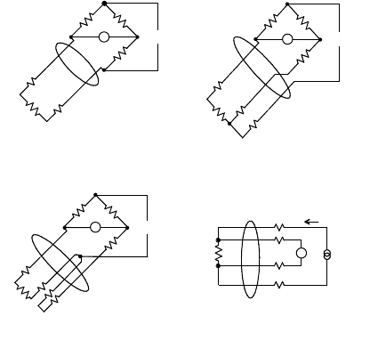
the lead temperature effects. For this reason, commercial RTDs are available with two, three, or four
wires going to the actual terminals of the resistor, depending on the technique used to handle the lead
effects as shown in Figure 20.58. The arrangement of Figure 20.58a is used where the lead lengths are
FIGURE 20.58 Various styles of commercial RTD probes and their application in reading circuits.
Excitation
R
L
R
L
R
L
R
L
RTD
RTD
RTD
V
Excitation
Excitation
(a) Two wire (b) Three wire
RTD
(c) Four wire with lead loop (d) Four wire
i
V
V
V
9258_C020_Sec_4-6.fm Page 81 Tuesday, October 9, 2007 9:09 PM
20-82 Mechatronic Systems, Sensors, and Actuators
short, the resistance of the RTD is high compared to the lead resistance, or where high accuracy is not
required. Three wire RTDs, Figure 20.58b, allow an equal length of lead wire to be included in each
side of the bridge so that changes in lead resistances are felt equally on both sides and the balance of
the bridge is not affected. It should be noted that four-wire RTDs of the type shown in Figure 20.58d
can be used with readers designed for two-, three-, or four-wire RTDs and unless expense or size is a
concern, they are recommended to allow for future upgrades of the reader. A fairly rare alternate
configuration of a four wire RTD probe is shown in Figure 20.58c where two of the lead wires form a
closed loop. This arrangement usually is needed only when multiple RTDs are in the bridge and should
not be confused with the other type of four-wire RTD shown in Figure 20.58d, which has two wires
going to each side of the resistor.
Another problem common to all reading schemes is that of self-heating of the RTD due to the
measuring current through the resistor. This can be minimized by using small currents, having a high
heat transfer coefficient between the sensor and the measured process, or by using low duty time pulsed
measurements. Although steps can be taken to minimize it, self-heating can never be eliminated. It is
such a ubiquitous characteristic of RTDs that it can be exploited as a means of determining the heat
transfer coefficient of a system, such as when platinum resistors are used as anemometers.
As indicated above, the measurement of temperature using an RTD simply requires determining its
resistance. The three conventional techniques are briefly discussed here.
Fully Balanced Bridges
A primitive but highly accurate means of determining the resistance of an RTD is to use it in one leg of
a wheatstone bridge and have a calibrated variable resistor in the opposite leg such that when the bridge
is brought to balance, as indicated by a null current on a galvanometer, the resistance of the RTD is the
same as the calibrated variable resistor. There are several variations on this theme to eliminate most
sources of error by splitting the error-forming device between legs of the bridge. For example, if the
RTD is remote from the bridge, a three-wire lead configuration can be used to put an equal length of
lead wire in both sides of the bridge with the “corner” of the bridge now defined at the remote RTD
location as shown in Figure 20.58b. Ultimately the accuracy of the reading is limited by the accuracy
of the resistances in the bridge, which can be made quite accurate. Since the variable resistor must be
physically adjusted to null the bridge, this technique is not readily adapted to data loggers or temperature
displays.
Unbalanced Bridges
If the calibrated variable resistor in the above scheme is replaced by a fixed resistor, the extent of the
imbalance of the bridge can be measured with a voltmeter in place of the nulling galvanometer. This
technique is fraught with errors since the imbalance of the bridge is not linear with the resistance of the
RTD and the reading of the voltmeter is also proportional to the excitation current. Nevertheless, this
can be a practical means of measuring temperatures over a narrow range if the values of the resistors in
the far legs of the bridge are much higher than the RTD and the opposite leg resistance is close to that
of the RTD. As with the other bridge techniques, three lead wires can be arranged in opposite legs of the
bridge for remote sensors to compensate for lead resistance changes. If opposite legs of the bridge both
consist of RTDs, then the bridge imbalance is proportional to the difference in the temperature of the
two RTDs and the only way to keep equal lead lengths in both legs is to use the special four-wire type
shown in Figure 20.58c.
Direct Voltage versus Current Measurements
If a constant current is passed through a resistor, the voltage across it is proportional to resistance. This
is a simple concept but had to await the advent of accurate constant current sources and high impedance
voltage amplifiers to become a practical replacement to the bridge techniques. By using four lead wires,
as shown in Figure 20.58d, the current circuit can be made independent of the voltage sensing circuit
and the lead resistances have no affect on the reading.
9258_C020_Sec_4-6.fm Page 82 Tuesday, October 9, 2007 9:09 PM
Sensors 20-83
20.6.4.3 Thermistors
Thermistors are bulk semiconductors made from an oxide of nickel, cobalt, manganese, or other metal.
The oxide is ground to a fine powder and then sintered to produce the actual thermistor material that
is then incorporated into a sensor. Thermistors are resistance temperature sensing devices with several
notable differences from RTDs such as their large negative temperature coefficients, and extreme nonlinear
response. The resistance of a thermistor is usually so large (several thousand ohms) that lead wire
resistance is rarely a concern. Thus, they are inevitably two-wire devices unless multiple thermistors or
components are included in the probe. There must be some means of electrical bonding between the
wire leads and the thermistor semiconductor. This bonding and the typical epoxy encapsulation places
a limit on the maximum usable temperature, even though the thermistor itself is a refractory material.
There are several schemes for dealing with the nonlinearity of thermistors, ranging from applying a
correction curve with a computer to having multiple thermistors with differing characteristics complete
with nonthermal resistors as a bridge within a single encapsulated probe. For moderate temperatures
spanning 200 K, a simple external bridge can be used to linearize the signal.
Although not normally called thermistors, germanium, silicon, and carbon are semiconductors that
can also be used to monitor temperatures by measuring their resistance. Germanium is used for very
precise measurements at cryogenic temperatures down to less than 1 K. The change in resistance can
be very large and very nonlinear, but still very repeatable with a typical unit going from 7000 Ω at
2K to 6 Ω at 60 K (Doebelin, 1990). Silicon can be used at room temperature and, depending on its
doping, can have a very steep temperature curve. It is rarely used as a temperature sensor since other
methods work better over its useful range of –200°C to 200°C. Carbon resistors out of a parts drawer
found in any laboratory can be used for cryogenic measurements from 1 to 20 K, but they must be
individually calibrated.
20.6.4.4 Integrated Circuit Temperature Sensors
The base-to-emitter voltage drop of a transistor operating at a constant current is a simple function of
absolute temperature. Thus, any transistor can be used as a temperature sensor. In reality, this is much
more of a problem with building thermally stable electronics than a convenient means of measuring
temperature. Integrated circuits are available that monitor the collector current, amplify, and linearize
the base-to-emitter voltage to yield an output that is proportional to absolute temperature. Common
integrated circuit temperature sensors are available with outputs of 10 mV/K, or 1
µ
A/K. The temperature
range over which they may be used is limited to −50°C to 150°C by the construction techniques of
integrated circuits. This makes them very useful for referencing one junction of the thermocouple and
most ambient temperature measurements. Although not intrinsically water proof, the ICs are small metal
cans or plastic cases resembling signal transistors and can be potted or used in thermowells.
The IC sensors with a voltage output are commonly two terminal devices, with a possible optional lead
for trimming the response. When a small current of about 1 mA is allowed to pass through it, it will have a
voltage drop directly proportional to the absolute temperature (National, 2000). Even simpler IC transducers
are available with separate excitation and signal leads. These are usually calibrated to 10 mV/
°
F or
°
C. These
have an inherent limitation of not being able to measure below a few degrees above 0
°
F or 0
°
C unless both
positive and negative power supplies are available.
Voltage output ICs are very convenient where the temperature being monitored is local to the readout
and the voltage drop across the lead wires is not a concern, but for remote sensors, which require long
lines, current sensors are preferred. Current sensors are also two terminal devices that behave as high
impedance current sources so whatever lead resistance present may increase the voltage, but will not affect
the current through the sensor (Analog, 1997). Both types can be individually adjusted by trimming resis-
tances on the chip with a laser during manufacture to provide the rated output or they can have an external
adjustment lead. Even with trimming and calibration, the accuracy over the entire span from −50°C to
+150°C is rarely better than two or three degrees. Several individual ICs may be hooked up to give
minimum or average temperature. Voltage ICs are placed in parallel for minimum temperature and in
9258_C020_Sec_4-6.fm Page 83 Tuesday, October 9, 2007 9:09 PM