Bichop R.H. (Ed.) Mechatronic Systems, Sensors, and Actuators: Fundamentals and Modeling
Подождите немного. Документ загружается.

17-6 Mechatronic Systems, Sensors, and Actuators
speed proportional to the flow rate. The
electromagnetic flow meters
use noncontact method. Magnetic
field is applied in the transverse direction of the flow, and the fluid acts as the conductor to induce voltage
proportional to the flow rate.
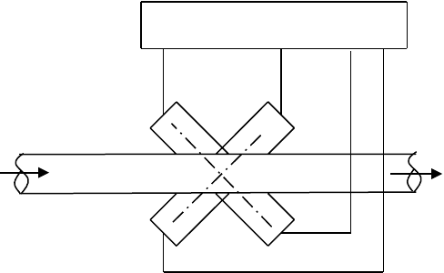
Ultrasonic flow meters measure fluid velocity by passing high-frequency sound waves through fluid. A
schematic diagramof the ultrasonic flowmeter is as shown in Figure 17.4. The transmitters (T) provide
the sound signal source. As the wave travels toward the receivers (R), its velocity is influenced by the
velocity of the fluid flow due to the doppler effect. The control circuit compares the time to interpret
the flow rate. This can be used for very high flow rates and also be used for both upstream and downstream
flow. The other advantage is that it can be used for corrosive fluids, fluids with abrasive particles as it is
like a noncontact sensor.
Temperature Sensors: A variety of devices are available to measure temperature. The most common
devices are thermocouples, thermisters, resistance temperature detectors (RTDs), and infrared type.
Thermocouples are the most versatile, inexpensive, and have a wide range (up to 1200⬚C typical).
Thermocouple simply consists of two dissimilar metal wires joined at the ends to create the sensing
junction. When used in conjunction with a reference junction, the temperature difference between the
reference junction and the actual temperature shows up as a voltage potential. Thermisters are semicon-
ductor devices whose resistance changes as the temperature changes. They are good for very high
sensitivity measurements in a limited range of up to 100⬚C. The relationship between the temperature
and the resistance is nonlinear. The RTDs use the phenomenon that the resistance of a metal changes
with temperature. They are, however, linear over a wide range and are most stable.
Infrared type sensors use the radiation heat to sense the temperature froma distance. These noncontact
sensors can also be used to sense a field of vision to generate thermal map of a surface.
Proximity Sensors: They are used to sense the proximity of an object relative to another object. They
usually provide a “on” or “off” signal indicating the presence or absence of an object. Inductance,
capacitance, photoelectric, and Hall effect type are widely used as proximity sensors. Inductance proximity
sensor consists of a coil wound around a soft iron core. The inductance of the sensor changes when a
ferrous object is in its proximity. This change is converted to a voltage-triggered switch. Capacitance type
is similar to inductance except the proximity of an object changes the gap and affects the capacitance.
Photoelectric sensors are normally aligned with an infrared light source. The proximity of amoving object
interrupts the light beam, causing the voltage level to change. Hall effect voltage is produced when a
current-carrying conductor is exposed to transverse magnetic field. The voltage is proportional to trans-
verse distance between the Hall effect sensor and an object in its proximity.
Light Sensors
: Light intensity and full field vision are two important measurements used in many control
applications.
Phototransistors, photoresistors
, and
photodiodes
are some of the more common type of light
intensity sensors. A common photoresistor is made of cadmium sulphide, whose resistance is maximum
FIGURE 17.4 Ultrasonic flow sensor arrangement.
T
T
R
R
Control unit
N9258-17.fm Page 6 Thursday, October 4, 2007 9:44 PM
Introduction to Sensors and Actuators 17-7
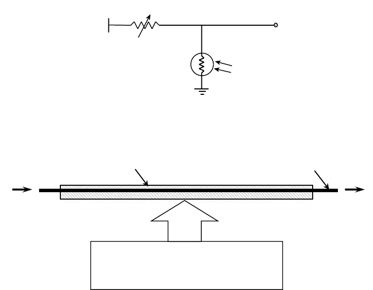
when the sensor is in dark. When the photoresistor is exposed to light, its resistance drops in proportion
to the intensity of light. When interfaced with a circuit as shown in Figure 17.5 and balanced, the change
in light intensity will show up as change in voltage. These sensors are simple, reliable, and cheap, used
widely for measuring light intensity.
Smart Material Sensors: There are many new smart materials that are gaining more applications as
sensors, especially in distributed sensing circumstances. Of these, optic fibers, piezoelectric, and magneto-
strictive materials have found applications.Within these, optic fibers are most used.
Optic fibers can be used to sense strain, liquid level, force, and temperature with very high resolution.
Since they are economical for use as
in situ
distributed sensors on large areas, they have found numerous
applications in smart structure applications such as damage sensors, vibration sensors, and cure-
monitoring sensors. These sensors use the inherent material (glass and silica) property of optical fiber
to sense the environment. Figure 17.6 illustrates the basic principle of operation of an embedded optic
fiber used to sense displacement, force, or temperature. The relative change in the transmitted intensity
or spectrum is proportional to the change in the sensed parameter.
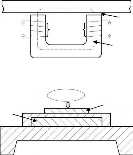
Magnetostrictive sensor can be used to measure external load, force, pressure, vibration, temperature,
and flow rates. These sensors sense the signal according to Villari effect. Figure 17.7 shows the general
configuration of a C-shaped ferromagnetic sensor core wounded with the excitation and sensing coils.
It can be used to detect the strain in target ferromagnetic materials. A change of strain in the target changes
the magnetic circuit permeability, which shows up as a change in sensed voltage.
NBC Sensors: They have become extremely important for homeland security-related applications. The
detection of nuclear, biological, and chemical agents is an active research area. The ultimate goal is to
develop an all-in-one sensor that has multifunction and has a low cost.
FIGURE 17.5 Light sensing with photoresistors.
FIGURE 17.6 Principle of operation of optic fiber sensing.
v
out
5V
Potentiometer
Photo
resistor
Light
Known source
of light
Relative change in
intensity or spectrum
or phase
Optical fiber
Host material
Environmental disturbance
e.g., deflection, or temperature,
or force
N9258-17.fm Page 7 Thursday, October 4, 2007 9:44 PM
17-8 Mechatronic Systems, Sensors, and Actuators
Nuclear sensors are used to detect all kinds of radiations such as alpha, gamma, beta, and x-rays. They
have high sensitivity in a wide range of radiation levels. Biological Sensors/Biosensors that include a
biological entity are used to detect the target substances such as blood glucose concentration, organo-
phosphate, pesticides, and other health-related targets.
Chemical sensors are used to sense particular chemical components such as various gas species. It
includes chemiresistor sensor, chemicapacitor sensor, chemimechanical sensor, and metal oxide gas
sensor. Figure 17.8 shows a general metal oxide gas sensor diagram. Metal oxide changes electric resistance
after absorbing certain gases. Catalyst deposition such as platinum (Pt) can speed up the reaction and
hence increase the sensitivity of the sensor. The heater keeps the film at a constant temperature.
Micro and NanoSensors: Microsensors are the miniaturized version of the conventional macrosensors,
with improved performance and reduced cost. Silicon micromachining technology has helped the devel-
opment of many microsensors and continues to be one of the most active research and development
topic in this area.
Vision microsensors have found applications in medical technology. A
fiberscope
of approximately
0.2 mm in diameter has been developed to inspect flaws inside tubes. Another example is a
microtactile
sensor
that uses laser light to detect the contact between a catheter and the inner wall of blood vessels
during insertion, which has sensitivity in the range of 1 mN.
Similarly, the progress made in the area of nanotechnology has fuelled the development of nanosensors.
These are relatively new sensors that take one step further in the direction of miniaturization and are
expected to open new avenues for sensing applications.
Micro and nanoeletromechanical systems, called MEMS and NEMS in short, are the state-of-the art
devices in sensor technology. These devices are mainly fabricated in silicon and polymers with 3D litho-
graphic features of various geometries by many established techniques like photolithography and surface
micromachining. MEMS and NEMS have proved to be efficient, cost effective, faster, and easily mountable,
with low power consumption. Their advantages over the conventional sensors enable them to rapidly
widen their applications in automobile industry, drug testing laboratory, and consumer electronics.
FIGURE 17.7 Magnetostrictive strain sensor. 1—Sensor core; 2—excitation coil; 3—strained ferromagnetic mate-
rial; 4—sensing coil; 5—magnetic flux; 6—air gap (Teflon).
FIGURE 17.8 Metal oxide gas sensor. 1—metal oxide; 2—poly heater.
3
2
4
6
1
5
V
in
V
out
2
1
Measured gas
N9258-17.fm Page 8 Thursday, October 4, 2007 9:44 PM
Introduction to Sensors and Actuators 17-9
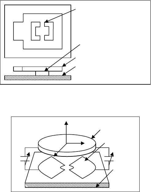
MEMS accelerometers measure the inertial acceleration when the seismic mass of the sensor moves.
Some of these MEMS devices use the principle of measuring acceleration by sensing piezoresistive stresses
and others measure by sensing the change of capacitance. Figure 17.9 shows the schematic of a micro-
machinable accelerometer based on capacitive sensing. The device is fabricated as two layers each to act
as a plate of parallel plate capacitor with top plate supported by a pedestal. Upper plate is made
asymmetrical so that the center of mass falls out of the torsion bar. When the upper plate rotates along
the axis of the torsion bar, it increases the distance between the plates on one side and decreases on other
side. The acceleration of the body causing the motion can be measured by sensing the capacitance
difference between the left and right side of the torsion bar.
There are many types of MEMS gyros based on the principle of their working, such as tuning fork
gyro, rotating wheel gyro, wine glass resonator gyro, and Foucault pendulum gyro. Figure 17.10 shows
the working principle of a rotating wheel gyro, which is similar to that of accelerometer. In this type of
gyro, the top wheel is driven to vibrate about its axis of symmetry; rotation about any of the in-plane
axes results in the wheel’s tilting, which results in a change in capacitance that can be detected with
capacitive electrodes under the wheel. With this device, it is possible to sense two axes of rotation with
a single vibrating wheel.
Figure 17.11 shows a MEMS pressure sensor that measures pressure by sensing the capacitance. The
device has a glass fixed plate and a parallel movable plate with each plate coated with a conducting
material. The two layers of conducting material act as two plates of a parallel plate capacitor. When an
external pressure acts on the movable plate, it changes the clearance between the plates and in turn
changes the capacitance. The pressure applied can be estimated by measuring the new capacitance.
FIGURE 17.9 MEMS accelerometer.
FIGURE 17.10 MEMS gyroscope.
Torsion bar
Upper capacitor mobile plate
Lower capacitor fixed plate
(substrate)
Pedestal
C
C
x
y
z
Rotor
Electrode
Substrate
N9258-17.fm Page 9 Thursday, October 4, 2007 9:44 PM
17-10 Mechatronic Systems, Sensors, and Actuators
BioMEMS can be defined as MEMS devices used for processing, delivery, manipulation, and analysis
of biological and chemical entities. Micro devices integrated with BioMEMS systems known as lab-on-
a-chip and micro-total analysis systems (micro-TAS or ATAS) already have wide variety of applications.
Biosensors are analytical devices that combine a biologically sensitive material with a physical or chemical
transducer to selectively and quantitatively sense the presence of specific chemical compounds in a given
environment. For example, amperometric biosensors detect by measuring the electric current associated
with the electrons involved in redox processes, whereas potentiometric biosensors measure a change in
potential at electrodes due to ions or chemical reactions at an electrode, and conductometric biosensors
measure conductance changes associated with changes in the overall ionic medium between the electrodes.
17.1.1.3 Selection Criteria
A number of static and dynamic factors must be considered in selecting a suitable sensor to measure the
desired physical parameter. Following is a list of typical factors:
Range
Difference between the maximum and minimum value of the sensed parameter
Resolution The smallest change the sensor can differentiate
Accuracy Difference between the measured value and the true value
Precision Ability to reproduce repeatedly with a given accuracy
Sensitivity Ratio of change in output to a unit change of the input
Zero offset A nonzero value output for no input
Linearity Percentage of deviation from the best-fit linear calibration curve
Zero Drift The departure of output from zero value over a period of time for no input
Response time The time lag between the input and output
Bandwidth Frequency at which the output magnitude drops by 3 dB
Resonance The frequency at which the output magnitude peak occurs
Operating temperature The range in which the sensor performs as specified
Deadband The range of input for which there is no output
Signal to noise ratio Ratio between the magnitudes of the signal and the noise at the output
Choosing a sensor that satisfies all the above to the desired specification is difficult, at best. For example,
finding a position sensor with micrometer resolution over a range of a meter eliminates most of the
sensors. Many times, the lack of a cost-effective sensor necessitates redesigning the mechatronics system.
It is therefore advisable to take a system-level approach when selecting a sensor, and avoid choosing it
in isolation.
Once the above-referred functional factors are satisfied, a short list of sensors can be generated. The
final selection will then depend on the size, extent of signal conditioning, reliability, robustness, main-
tainability, and cost.
FIGURE 17.11 MEMS pressure sensor.
Glass
Fixed plate
Movable plate
Silicon
External pressure
N9258-17.fm Page 10 Thursday, October 4, 2007 9:44 PM
Introduction to Sensors and Actuators 17-11
17.1.1.4 Signal Conditioning
Normally, the output from a sensor requires postprocessing of the signals before they can be fed to the
controller. The sensor outputmay have to be demodulated, amplified, filtered, linearized, range quantized,
and isolated so that the signal can be accepted by a typical analog to digital converter of the controller.
Some sensors are available with integrated signal conditioners such as the microsensors. All the electronics
are integrated into one microcircuit and can be directly interfaced with the controllers.
17.1.1.5 Calibration
The sensor manufacturer usually provides the calibration curves. If the sensors are stable with no drift,
there is no need to recalibrate. However, often the sensor may have to be recalibrated after integrating it
with signal conditioning system. This essentially requires that a known input signal is provided to the
sensor and its output recorded to establish a correct output scale. This process proves the ability to measure
reliably and enhances the confidence.
If the sensor is used to measure a time-varying input, then dynamic calibration becomes necessary.
Use of sinusoidal inputs is the most simple and reliable way of dynamic calibration. However, if generating
sinusoidal input becomes impractical (e.g., temperature signals), then a step input can substitute for the
sinusoidal signal. The transient behavior of step response should yield sufficient information about the
dynamic response of the sensor.
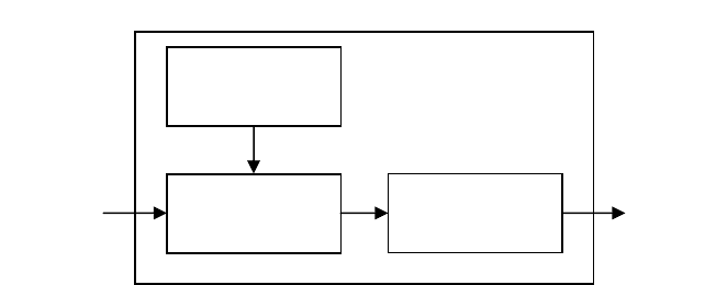
17.1.2 Actuators
Actuators are basically the muscle behind a mechatronics system that accepts a control command (mostly
in the form of an electrical signal) and produces a change in the physical system by generating force,
motion, heat, flow, and so forth. Normally, the actuators are used in conjunction with the power supply
and a coupling mechanism as shown in Figure 17.12. The power unit provides either ac or dc power at
the rated voltage and current. The coupling mechanism acts as the interface between the actuator and
the physical system. Typical mechanisms include rack and pinion, gear drive, belt drive, lead screw and
nut, piston, and linkages.
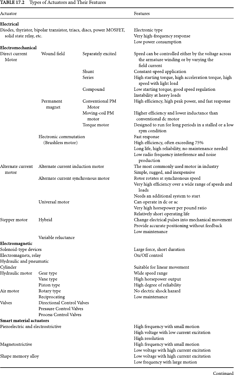
17.1.2.1 Classication
Actuators can be classified on the basis of the type of energy as listed in Table 17.2. The table, although
not exhaustive, lists all the basic types. They are essentially of electrical, electromechanical, electromag-
netic, pneumatic, or hydraulic type. The new generations of actuators include smart material actuators,
microactuators, and nanoactuators.
Actuators can also be classified as
binary
and
continuous
on the basis of the number of stable state
outputs. A relay with two stable states is a good example of a binary actuator. Similarly, a stepper motor
FIGURE 17.12 A typical actuating unit.
To
controlled
system
Actuating unit
From
controller
Power
supply
Actuator
Coupling
mechanism
N9258-17.fm Page 11 Thursday, October 4, 2007 9:44 PM
17-12 Mechatronic Systems, Sensors, and Actuators
N9258-17.fm Page 12 Thursday, October 4, 2007 9:44 PM
Introduction to Sensors and Actuators 17-13
is a good example of continuous actuator. When used for a position control, the stepper motor can
provide stable outputs with very small incremental motion.
17.1.2.2 Principle of Operation
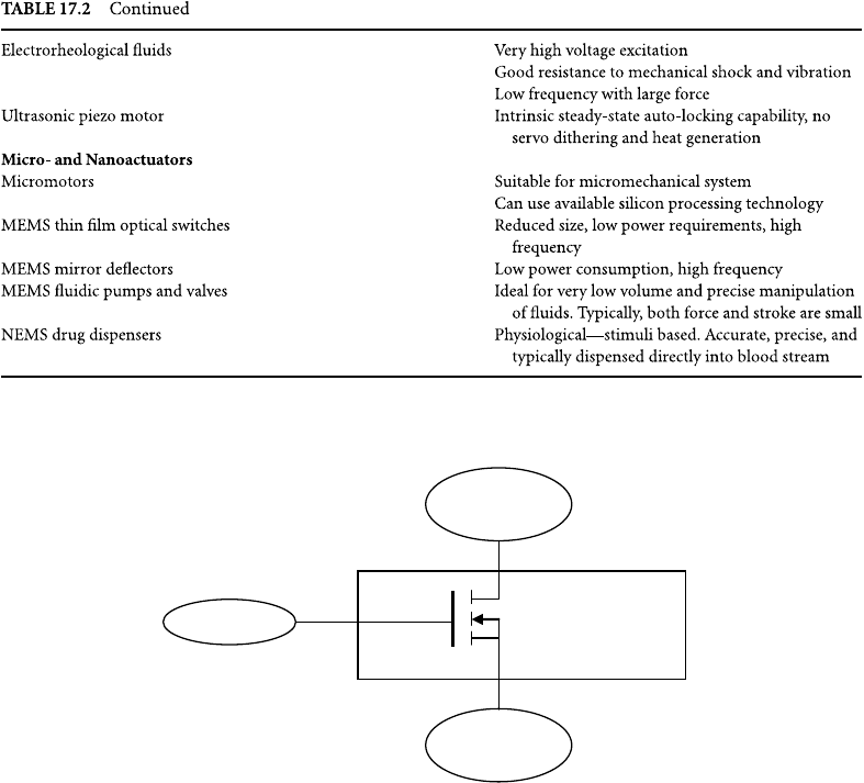
Electrical Actuators: Electrical switches are the choice of actuators for most of the on–off type control
action. Switching devices such as diodes, transistors, triacs, MOSFET, and relays accept a low energy level
command signal from the controller and switch on or off electrical devices such as motors, valves, and
heating elements. For example, a MOSFET switch is shown in Figure 17.13. The gate terminal receives
the low energy control signal from the controller that makes or breaks the connection between the power
supply and the actuator load. When switches are used, the designer must make sure that switch bounce
problem is eliminated either by hardware or software.
Electromechanical Actuators: The most common electromechanical actuator is a motor that converts
electrical energy to mechanical motion. Motor is the principal means of converting electrical energy
into mechanical energy in industry. Broadly they can be classified as dc motors, ac motors, and stepper
motors. Direct current motors operate on dc voltage, and varying the voltage can easily control their
speed. They are widely used in applications ranging from thousands of horsepower motors used in rolling
mills to fractional horsepower motors used in automobiles (starter motors, fan motors, windshield wiper
motors, etc.). They are, however, costlier, need dc power supply, and requiremore maintenance compared
to ac motors.
FIGURE 17.13 n-Channel power MOSFET.
Controller
Power
supply
Gate
Source
Drain
Load
N9258-17.fm Page 13 Thursday, October 4, 2007 9:44 PM
17-14 Mechatronic Systems, Sensors, and Actuators
The governing equation of motion of a dc motor can be written as:
where T is torque, J is the, total inertia,
is the angular mechanical speed of the rotor, T
L
is the torque
applied to the motor shaft, and T
loss
is the internal mechanical losses such as friction.
Alternate current motors are the most popular motors since they use standard ac power, do not require
brushes and commutator, and are therefore less expensive. Alternate current motors can be further
classified as the induction motors, synchronous motors, and universal motors according to their physical
construction. The induction motor is simple, rugged, and maintenance free. They are available in many
sizes and shapes on the basis of the number of phases used. For example, a three-phase induction motor
is used in large horsepower applications, such as pump drives, steel mill drives, hoist drives, and vehicle
drives. The two-phase servomotor is used extensively in position control system. Single-phase induction
motors are widely used in many household appliances. The synchronous motor is one of the most efficient
electrical motors in industry, so it is used in industry to reduce the cost of electrical power. In addition,
synchronous motor rotates at synchronous speed, so it is also used in applications that require synchro-
nous operations. The universal motors operate with either ac or dc power supply. It is normally used in
fractional horsepower application. The dc universal motor has the highest horsepower-per-pound ratio,
but has a relatively short operating life.
The stepper motor is a discrete (incremental) positioning device that moves one step at a time for each
pulse command input. Since they accept direct digital commands and produce a mechanical motion, the
stepper motors are used widely in industrial control applications. They are mostly used in fractional
horsepower applications. With the rapid progress in low cost and high-frequency solid-state drives, they
are finding increased applications.
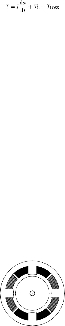
Figure 17.14 shows a simplified unipolar stepper motor. The winding-1 is between the top and bottom
stator pole, and the winding-2 is between the left and right motor poles. The rotor is a permanent magnet
with six poles resulting in a single-step angle of 30⬚. With appropriate excitation of winding-1, the top
stator pole becomes a north pole and the bottom stator pole becomes a south pole. This attracts the
rotor into the position as shown. Now if the winding-1 is de-energized and winding-2 is energized, the
rotor will turn 30⬚. With appropriate choice of current flow through winding-2, the rotor can be rotated
either clockwise or counterclockwise. By exciting the two windings in sequence, the motor can be made
to rotate at a desired speed continuously.
Electromagnetic Actuators: Solenoid is the most common electromagnetic actuator. Direct current
solenoid actuator consists of a soft iron core enclosed within a current-carrying coil. When the coil is
energized, a magnetic field is established that provides the force to push or pull the iron core. Alternate
current solenoid devices are also encountered, such as ac excitation relay.
FIGURE 17.14 Unipolar stepper motor.
2
2
1
N
1
S
S
N
N
S
S
N
N9258-17.fm Page 14 Thursday, October 4, 2007 9:44 PM
Introduction to Sensors and Actuators 17-15
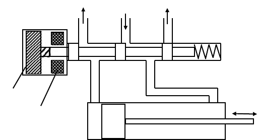
A solenoid-operated directional control valve is shown in Figure 17.15. Normally, due to the spring
force the soft iron core is pushed to the extreme left position as shown. When the solenoid is excited,
the soft iron core will move to the right extreme position, thus providing the electromagnetic actuation.
Another important type is the electromagnet. The electromagnets are used extensively in applications
that require large forces.
Hydraulic and Pneumatic Actuators: Hydraulic and pneumatic actuators are normally either rotary
motors or linear piston/cylinder or control valves. They are ideally suited for generating very large forces
coupled with large motion. Pneumatic actuators use air under pressure that is most suitable for low to
medium force, short stroke, and high-speed applications. Hydraulic actuators use pressurized oil that is
incompressible. They can produce very large forces coupled with large motion in a cost-effective manner.
The disadvantage with the hydraulic actuators is that they are more complex and need more maintenance.
The rotary motors are usually used in applications where low speed and high torque are required. The
cylinder/piston actuators are suited for application of linear motion such as aircraft flap control. Control
valves in the form of directional control valves are used in conjunction with rotary motors and cylinders
to control the fluid flow direction as shown in Figure 17.15. In this solenoid-operated directional control
valve, the valve position dictates the direction motion of the cylinder/piston arrangement.
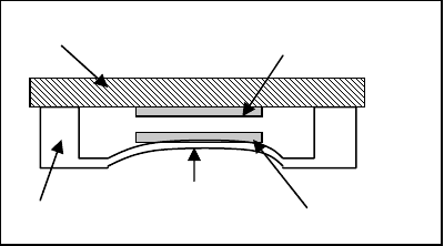
Smart Material Actuators: Unlike the conventional actuators, the smart material actuators typically
become part of the load-bearing structures. This is achieved by embedding the actuators in a distributed
manner and integrating into the load-bearing structure that could be used to suppress vibration, cancel
the noise, and change shape. Of the many smart material actuators, shape memory alloys (SMA), piezo-
electric (PZT), magnetostrictive, electrorheological fluids, and ion exchange polymers are most common.
Shape memory alloys are alloys of nickel and titanium, which undergo phase transformation when
subjected to thermal field. The SMAs are also known as NITINOL for Nickel Titanium Naval Ordnance
Laboratory. When cooled below a critical temperature, their crystal structure enters martensitic phase
as shown in Figure 17.16. In this state, the alloy is plastic and can easily be manipulated. When the alloy
is heated above the critical temperature (in the range of 50–80⬚C), the phase changes to austenitic phase.
Here the alloy resumes the shape that it formally had at the higher temperature. For example, a straight
wire at room temperature can be made to regain its programmed semicircle shape when heated, which
has found applications in orthodontics and other tensioning devices. The wires are typically heated by
passing a current (up to several amperes at very low voltage, 2–10 V typical).
The
piezoelectric
actuators are essentially piezocrystals with top and bottom conducting films as shown
in Figure 17.17. When an electric voltage is applied across the two conducting films, the crystal expands
in the transverse direction as shown by the dotted lines.When the voltage polarity is reversed, the crystal
contracts thereby providing bidirectional actuation. The interaction between the mechanical and electrical
FIGURE 17.15 Solenoid-operated directional control valve.
Core
Solenoid
Supply
N9258-17.fm Page 15 Thursday, October 4, 2007 9:44 PM