Bhushan B. Nanotribology and Nanomechanics: An Introduction
Подождите немного. Документ загружается.

16 Nanotribology of Amorphous Carbon Films 879
0.5
0.4
0.3
0.2
0.1
0.0
0 25 50 75 100 125
0.5
0.4
0.3
0.2
0.1
0.0
0 25 50 75 100 125
0.5
0.4
0.3
0.2
0.1
0.0
0 25 50 75 100 125
Coefficient of friction
Coefficient of friction
Coefficient of friction
SP 5 nm
A
B
A
B
A
c)
SP 10 nm
SP 20 nm
Normal load
(μN)
Normal load
(μN)
Normal load
(μN)
2μm
0nm
20nm
2μm
0nm
20nm
2μm
0nm
20nm
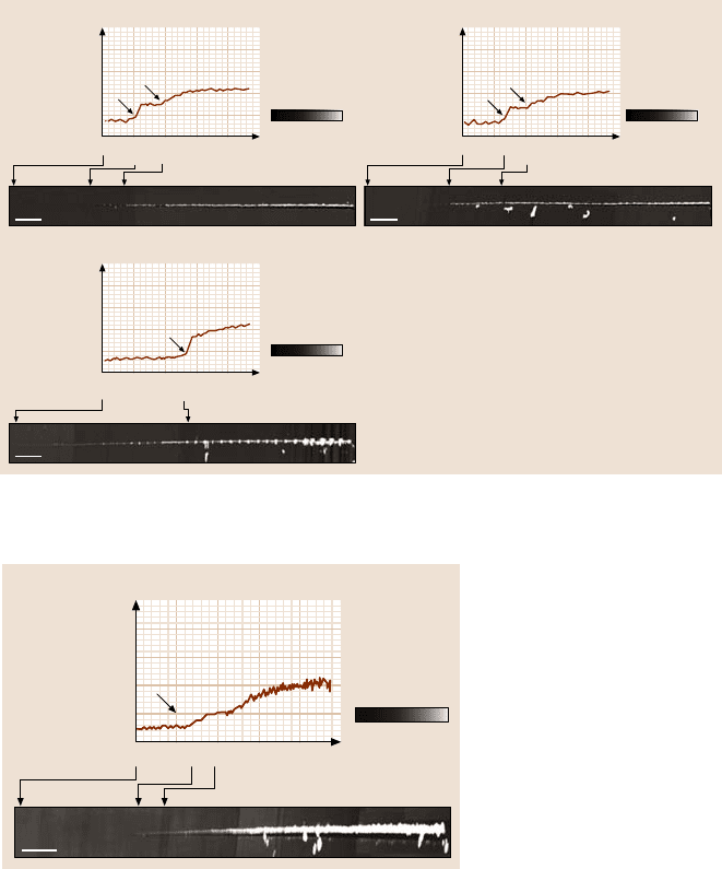
Fig. 16.18. (continued) Coefficient of friction profiles during scratch as a function of normal
load and corresponding AFM surface height maps for (c) SP coatings [99]
0.5
0.4
0.3
0.2
0.1
0.0
0 25 50 75 100 125
Coefficient of frictionSi(100)
Normal load
(μN)
2μm
0nm
20nm
Fig. 16.19. Coefficient of
friction profiles during
scratch as a function of nor-
mal load and corresponding
AFM surface height maps
for Si(100) [99]
A thicker coating is more difficult to break; the broken coating chips (debris) seen
for a thicker coating are larger than those for the thinner coatings. The different
residual stresses of coatings of different thicknesses may also affect the size of the
debris. The AFM image shows that the silicon substrate was damaged by plowing,
associated with the plastic flow of material. At and after the critical load, a small
amount of uniform debris is observed and the amount of debris increases with in-
creasing normal load.
Since the damage mechanism at the critical load appears to be the onset of plow-
ing, harder coatings with more fracture toughness will therefore require a higher
load for deformation and hence a higher critical load. Figure 16.21 gives critical
880 Bharat Bhushan
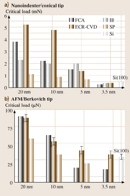
Fig. 16.20. Critical loads
estimated from the coefficient
of friction profiles from (a)
nanoindenter and (b)AFM
tests for various coatings
of different thicknesses and
Si(100) substrate
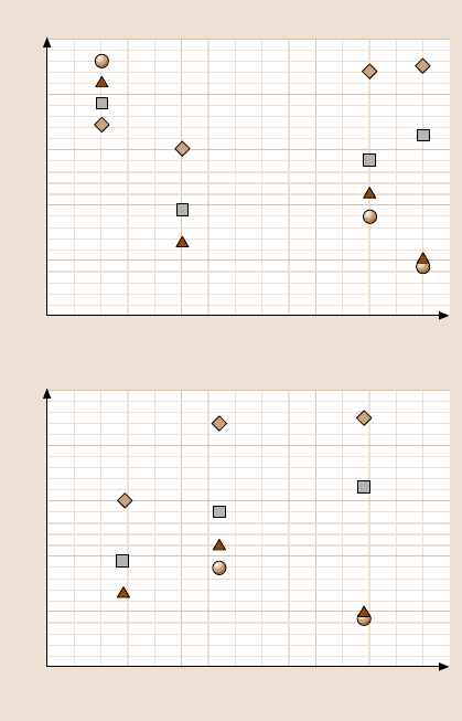
loads of various coatings, obtained with AFM tests, as a function of the coating
hardness and fracture toughness (from Table 16.5). It can be seen that, in general,
increasing coating hardness and fracture toughness results in a higher critical load.
The only exceptions are the FCA coatings at 5 and 3.5nm thickness, which show
the lowest critical loads despitetheir high hardness and fracturetoughness. The brit-
tleness of the thinner FCA coatings may be one reason for their low critical loads.
The mechanical properties of coatings that are less than 10nm thick are not known.
The FCA process may result in coatings with low hardness at low thickness due to
differences in coating stoichiometry and structure compared to coatings of higher
thickness. Also, at these thicknesses stresses at the coating–substrate interface may
affect coating adhesion and load-carrying capacity.
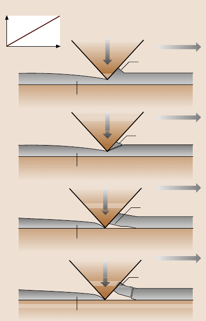
Based on the experimental results, a schematic of the scratch damage mechan-
isms encountered for the DLC coatings used in this study is shown in Fig. 16.22.
Below the critical load, if a coating has a good combination of strength and frac-
ture toughness, plowing associated with the plastic flow of materials is responsi-
ble for the coating damage (Fig. 16.22a). However, if the coating has a low frac-
16 Nanotribology of Amorphous Carbon Films 881
100
80
60
40
20
0
10 15 20 25
100
80
60
40
20
0
0 5 10 15
a)
Critical load (μN)
Hardness (GPa)
b)
Critical load (μN)
Fracture toughness (MPa m
1/2
)
3.5 nm
5
10
20
Fig. 16.21. Measured critical
loads estimated from the co-
efficient of friction profiles
fromAFMtestsasafunc-
tion of (a) coating hardness
and (b) fracture toughness.
Coating hardness and frac-
ture toughness values were
obtained using a nanoinden-
ter on 100 nm-thick coatings
(Table 16.5)
ture toughness, cracking could occur during plowing, resulting in the formation of
small amounts of debris (Fig. 16.22b). When the normal load is increased to the
critical load, delamination or buckling will occur at the coating/substrate interface
(Fig. 16.22c). A further increase in normalload will result in coating breakdownvia
through-coating thickness cracking, as shown in Fig. 16.22d. Therefore, adhesion
strength plays a crucial role in the determination of critical load. If a coating adheres
strongly to the substrate, the coating is more difficult to delaminate, which will re-
sult in a higher critical load. The interfacial and residual stresses of a coating may
also greatly affect the delamination and buckling [1]. A coating with higher interfa-
cial and residual stresses is more easily delaminated and buckled, which will result
in a low critical load. It was reported earlier that FCA coatings have higher residual
stresses than other coatings [47]. Interfacial stresses play an increasingly important
role as the coating gets thinner. A large mismatch in elastic modulus between the
FCA coating and the silicon substrate may cause large interfacial stresses. This may
be why thinner FCA coatings show lower critical loads than thicker FCA coatings,
882 Bharat Bhushan
Normal load
Scratch distance
a)
Plowed region
Plastic deformation
Scratch direction
Normal load
b)
c)
d)
Plowed region
Crack formation
in coating
Plowed region
Delamination
and buckling
Plowed region
Through coating
thickness crack
formation
Normal load
Scratch direction
Scratch direction
Scratch direction
Normal load
Normal load
Fig. 16.22. Schematic of
scratch damage mechanisms
for DLC coatings: (a)plow-
ing associated with the plastic
flow of materials, (b)plowing
associated with the formation
of small debris, (c) delam-
ination and buckling at the
critical load, and (d) break-
down via through-coating
thickness cracking at and af-
ter the critical load [48]
even though the FCA coatings have higher hardness and elastic moduli. The brit-
tleness of thinner FCA coatings may be another reason for the lower critical loads.
The strength and fracture toughness of a coating also affect the critical load. Greater
strength and fracture toughness will make the coating more difficult to break after
delamination and buckling. The high scratch resistance/adhesion of FCA coatings
is attributed to the atomic intermixing that occurs at the coating–substrate interface
due to the high kinetic energy (2keV) of the plasma formed during the cathodic arc
deposition process [57]. This atomic intermixing provides a graded compositional
transition between the coating and the substrate material. In all other coatings used
in this study, the kinetic energy of the plasma is insufficient for atomic intermixing.
Gupta and Bhushan [12,47] and Li and Bhushan [48,49] measured the scratch
resistances of DLC coatings deposited on Al
2
O
3
-TiC, Ni-Zn ferrite and single-
crystal silicon substrates. An interlayer of silicon is required to adhere the DLC
coating to other substrates, except in the case of cathodic arc-deposited coatings.
16 Nanotribology of Amorphous Carbon Films 883
The best adhesion with cathodic arc carbon coating is obtained on electrically con-
ducting substrates such as Al
2
O
3
-TiC and silicon rather than Ni-Zn ferrite.
Microwear
Microwear studies can be conducted using an AFM [23]. For microwear studies,
a three-sided pyramidal single-crystal natural diamond tip with an apex angle of
about 80
◦
and a tip radius of about 100 nm is used at relatively high loads of 1–
150µN. The diamond tip is mounted on a stainless steel cantilever beam with a nor-
mal stiffness of about 30N/m. The sample is generally scanned in a direction or-
thogonal to the long axis of the cantilever beam (typically at a rate of 0.5Hz).The
tip is mountedon the beam such that one of its edges is orthogonal to the beam axis.
In wear studies, an area of 2µm×2µm is typically scanned for a selected number
of cycles.
Microwear studies of various types of DLC coatings have been conducted [50,
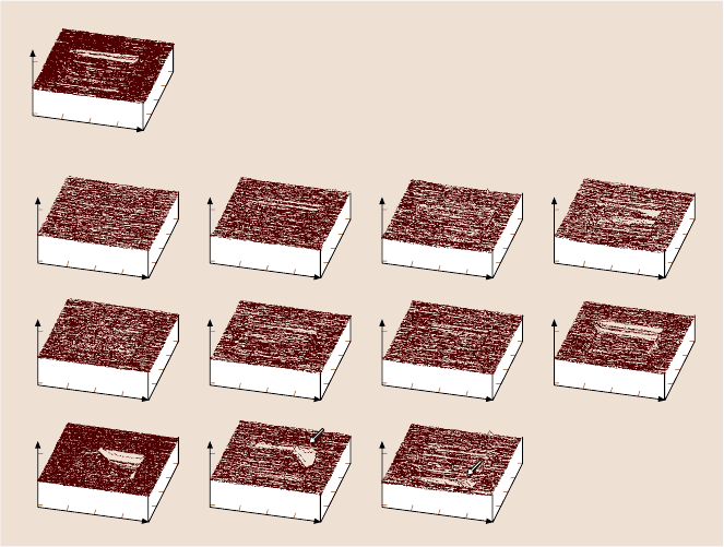
102,103]. Figure 16.23a shows a wear mark on uncoated Si(100). Wear occurs uni-
formly and material is removed layer-by-layer via plowing from the first cycle, re-
sulting in constant friction force during the wear (Fig. 16.24a). Figure 16.23b shows
AFM images of the wear marks on 10nm-thick coatings. It is clear that the coatings
wear nonuniformly. Coating failure is sudden and accompanied by a sudden rise
100
50
0
100
50
0
100
50
0
100
50
0
0
1.00
0
1.00
3.00
4.00
0
0
2.00
3.00
4.00
μm
2.00
0
1.00
0
1.00
3.00
4.00
0
0
2.00
3.00
4.00
μm
2.00
0
1.00
0
1.00
3.00
4.00
0
0
2.00
3.00
4.00
μm
2.00
0
1.00
0
1.00
3.00
4.00
0
0
2.00
3.00
4.00
μm
2.00
0
1.00
0
1.00
3.00
4.00
0
0
2.00
3.00
4.00
μm
2.00
0
1.00
0
1.00
3.00
4.00
0
0
2.00
3.00
4.00
μm
2.00
0
1.00
0
1.00
3.00
4.00
0
0
2.00
3.00
4.00
μm
2.00
0
1.00
0
1.00
3.00
4.00
0
0
2.00
3.00
4.00
μm
2.00
0
1.00
0
1.00
3.00
4.00
0
0
2.00
3.00
4.00
μm
2.00
0
1.00
0
1.00
3.00
4.00
0
0
2.00
3.00
4.00
μm
2.00
0
1.00
0
1.00
3.00
4.00
0
0
2.00
3.00
4.00
μm
2.00
0
1.00
0
1.00
3.00
4.00
0
0
2.00
3.00
4.00
μm
2.00
Si(100)
FCA IB ECR–CVD SP
nm
W=45μN
1 cycle
d = 0.8 nm
nm
13 cycles
d=2nm
nm
16 cycles
d =22nm
nm
17 cycles
d =23nm
nm
12 cycles
d=3nm
nm
W=45μN
3 cycles
d=2.5 nm
nm
W=60μN
5 cycles
d=2nm
nm
30 cycles
d= 2.5nm
nm
48 cycles
d=18nm
nm
2 cycles
d=13nm
nm
W=35μN
1 cycle
d=8nm
nm
W=20μN
2 cycles
d=8 nm
10 nm
a)
b)
Fig. 16.23. AFM images of wear marks on (a) bare Si(100), and (b) various 10 nm-thick DLC
coatings [50]
884 Bharat Bhushan
25.0
12.5
0.0
0.4
0.2
0.0
25.0
12.5
0.0
0.4
0.2
0.0
25.0
12.5
0.0
0.4
0.2
0.0
25.0
12.5
0.0
0 10 20 30 40 50 0 10 20 30 40 50 0 10 20 30 40 50
01020304050
0.2
0.0
25.0
12.5
0.0
0.4
0.2
0.0
0 10 20304050
01020304050
01020304050
FCA SP
b)
Wear
depth
(nm)
Number of cycles
Coefficient
of friction
80μN
35μN
IB ECR– CVD
Wear depth
Coeff. of friction
20 nm
80μN
60μN
80μN
60μN
35μN
45μN
10 nm
35μN
45μN
60μN
45μN
35μN
20μN
5 nm
25μN
20μN
35μN
25μN
35μN
25μN
15μN
20μN
25μN
20μN
3.5 nm
25μN
20μN
25μN
20μN
a)
Si(100)
Wear
depth
(nm)
Number of cycles
Coefficient
of friction
Wear depth
Coeff. of friction
35μN
20μN
0 10 20 30 40 50 0 10 20 30 40 50 0 10 20 30 40 50
0 10 20 30 40 50 0 10 20 30 40 50 0 10 20 30 40 50
0 10 20 30 40 50 0 10 20 30 40 50 0 10 20 30 40 50
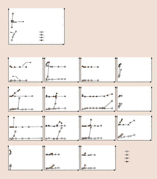
Fig. 16.24. Wear data for (a) bare Si(100) and (b) various DLC coatings. Coating thickness
is constant along each row in (b). Both the wear depth and the coefficient of friction during
wear are plotted for a given cycle [50]
in the friction force (Fig. 16.24b). Figure 16.24 shows the wear depth of Si(100)
substrate and various DLC coatings at two different loads. FCA- and ECR-CVD-
deposited20 nm-thick coatings show excellent wear resistanceup to 80µN, the load
that is required for the IB 20nm coating to fail. In these tests, “failure” of a coating
occurs when the wear depth exceeds the quoted coating thickness. The SP 20 nm
coating fails at a much lower load of 35µN. At 60 µN, the coating hardly provides
any protection. Moving on to the 10 nm coatings, the ECR-CVD coating requires
about 45 cycles at 60µN to fail, whereas the IB and FCA, coatings fail at 45 µN.
16 Nanotribology of Amorphous Carbon Films 885
The FCA coating exhibits slight roughening in the wear track after the first few cy-
cles, which leads to an increase in the friction force. The SP coating continues to
exhibit poor resistance, failing at 20 µN. For the 5 nm coatings, the load required
to make the coatings fail continues to decrease, but IB and ECR-CVD still provide
adequate protection compared to bare Si(100) in that order, with the silicon fail-
ing at 35 µN, the FCA coating at 25 µN and the SP coating at 20µN. Almost all of
the 20, 10, and 5 nm coatings provide better wear resistance than bare silicon. At
3.5 nm, FCA coating provides no wear resistance, failing almost instantly at 20µN.
The IB and ECR-CVD coatings show good wear resistance at 20µN compared to
bare Si(100). However, IB only lasts about ten cycles and ECR-CVD about three
cycles at 25µN.
The wear tests highlight the differences between the coatings more vividly than
the scratch tests. At higher thicknesses (10 and 20 nm), the ECR-CVD and FCA
coatings appear to show the best wear resistance. This is probably due to the greater
hardness of the coatings (see Table 16.5). At 5nm, the IB coating appears to be the
best. FCA coatings show poorer wear resistance with decreasing coating thickness.
This suggests that the trends in hardness seen in Table 16.5 no longer hold at low
thicknesses. SP coatings show consistently poor wear resistance at all thicknesses.
The 3.5nm IB coating does provide reasonable wear protection at low loads.
16.4.3 Macroscale Tribological Characterization
So far, we have presented data on mechanical characterization and microscratch and
microwear studies using a nanoindenter and an AFM. Mechanical properties affect
the tribological performance of a coating, and microwear studies simulate a single
asperity contact, which helps us to understand the wear process. These studies are
useful when screening various candidate coatings, and also aid our understanding
of the relationships between deposition conditions and properties of the samples. In
the next step, macroscale friction and wear tests need to be conducted to measure
the tribological performance of the coating.
Macroscale accelerated friction and wear tests have been conducted to screen
a large number of candidates, as have functional tests on selected candidates. An ac-
celerated test is designed to accelerate the wear process such that it does not change
the failure mechanism. The accelerated friction and wear tests are generally con-
ducted using a ball-on-flat tribometer under reciprocating motion [70]. Typically,
a diamond tip with a tip radius of 20 µm or a sapphire ball with a diameter of 3mm
and a surface finish of about 2nm RMS is slid against the coated substrates at se-
lected loads. The coefficient of friction is monitored during the tests.
Functional tests are conducted using an actual machine running at close to the
actual operating conditions for which the coatings have been developed. The tests
are generally accelerated somewhat to fail the interface in a short time.
Accelerated Friction and Wear Tests
Li and Bhushan [48] conducted accelerated friction and wear tests on DLC coat-
ings deposited by various deposition techniques using a ball-on-flat tribometer. The
886 Bharat Bhushan
FCA IB SP
200 μm
200 μm
200 μm
100 μm
Si(100)
200 μ
m
ECR-CVD
20 nm, 200 mN
10 nm, 200 mN
5 nm, 200 mN
3.5 nm, 200 mN
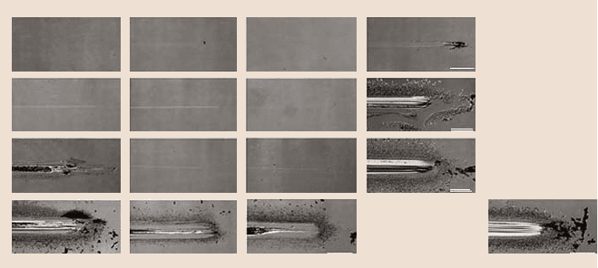
Fig. 16.25. Optical micrographs of wear tracks and debris formed on various coatings of
different thicknesses and silicon substrate when slid against a sapphire ball after a sliding
distance of 5 nm. The end of the wear track is on the right-hand side of the image
average coefficient of friction values observed are presented in Table 16.5. Opti-
cal micrographs of wear tracks and debris formed on all samples when slid against
a sapphire ball after a sliding distance of 5m are presented in Fig. 16.25. The nor-
mal load used for the 20 and 10nm-thick coatings was 200mN, andthe normal load
used for the 5 and 3.5nm-thick coatings and the silicon substrate was 150mN.
Among the 20nm-thick coatings, the SP coating exhibits a higher coefficient of
friction (about 0.3) than for the other coatings coefficient of friction (all of which
were about 0.2). The optical micrographsshow that the SP coating has a larger wear
track and moredebris than the IB coating. No wear trackor debris were foundon the
20nm-thick FCA and ECR-CVD coatings. The optical micrographs of 10nm-thick
coatings show that the SP coating was severely damaged, showing a large wear track
with scratches and lots of debris. The FCA and ECR-CVD coatings show smaller
wear tracks and less debris than the IB coatings.
For the 5 nm-thick coatings, the wear tracks and debris of the IB and ECR-CVD
coatings are comparable. The bad wear resistance of the 5nm-thick FCA coating is
in good agreement with the low critical scratch load, which may be due to thehigher
interfacial and residual stresses as well as the brittleness of the coating.
At 3.5nm, all of the coatings exhibit wear. The FCA coating provides no wear
resistance, failing instantly like the silicon substrate. Large block-like debris is ob-
served on the sides of the wear track of the FCA coating. This indicates that large
region delamination and buckling occurs during sliding, resulting in large block-like
debris. This block-like debris, in turn, scratches the coating, making the damage to
the coating even more severe. The IB and ECR-CVD coatings are able to provide
some protection against wear at 3.5nm.
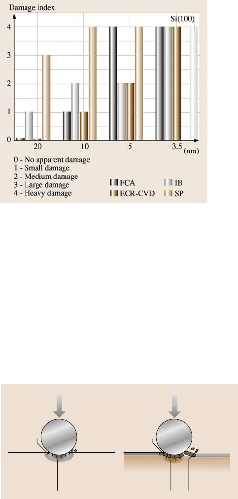
In order to better evaluate the wear resistance of various coatings, based on
an optical examination of the wear tracks and debris after tests, a bar chart of the
wear damage index for various coatings of different thicknesses and an uncoated
16 Nanotribology of Amorphous Carbon Films 887
Fig. 16.26. Bar chart of the
wear damage indices for
various coatings of differ-
ent thicknesses and Si(100)
substrate based on optical ex-
amination of the wear tracks
and debris
silicon substrate is presented in Fig. 16.26. Among the 20 and 10nm-thick coatings,
the SP coatings show the worst damage, followed by FCA/ECR-CVD. At 5 nm,
the FCA and SP coatings show the worst damage, followed by the IB and ECR-
CVD coatings. All of the 3.5nm-thick coatings show the same heavy damage as the
uncoated silicon substrate.
The wear damage mechanisms of the thick and thin DLC coatings studied are
believed to be as illustrated in Fig. 16.27. In the early stages of sliding, deformation
zone, Hertzian and wear fatigue cracks that have formed beneath the surface extend
within the coating upon subsequent sliding [1]. Formationof fatiguecracks depends
on the hardness and subsequentcycles. These are controlled by the sp
3
-to-sp
2
ratio.
For thicker coatings, the cracks generally do not penetrate the coating. For a thinner
coating, the cracks easily propagate down to the interface aided by the interfacial
Normal load
Thick coating
Normal load
Sliding
direction
Thin coating
Delamination
and buckling
Cracks
Substrate
Cracks
Deformation
zone
Substrate
Sliding
direction
Deformation
zone
Fig. 16.27. Schematic of wear damage mechanisms for thick and thin DLC coatings [48]
888 Bharat Bhushan
stresses and get diverted along the interface just enough to cause local delamination
of the coating. When this happens, the coating experiences excessive plowing. At
this point, the coating fails catastrophically, resulting in a sudden rise in the coef-
ficient of friction. All 3.5 nm-thick coatings failed much quicker than the thicker
coatings. It appears that these thin coatings have very low load-carrying capaci-
ties and so the substrate undergoes deformation almost immediately. This generates
stresses at the interface that weaken the coating adhesion and lead to delamination
of the coating. Another reason may be that the thickness is insufficient to produce
a coating that has the DLC structure. Instead, the bulk may be made up of a ma-
trix characteristic of the interface region where atomic mixing occurs with the sub-
strate and/or any interlayer used. This would also result in poor wear resistance and
silicon-like behavior of the coating, especially for FCA coatings, which show the
worst performance at 3.5nm. SP coatings show the worst wear performance at any
thickness (Fig. 16.25). This may be due to their poor mechanical properties, such as
lower hardness and scratch resistance, compared to the other coatings.
Comparisonof Figs. 16.20 and 16.26 shows a very good correlation betweenthe
wear damage and critical scratch loads. Less wear damage corresponds to a higher
critical scratch load. Based on the data, thicker coatings do show better scratch
and wear resistance than thinner coatings. This is probably due to the better load-
carrying capacities of the thick coatings compared to the thinner ones. For a given
coating thickness, increased hardness and fracture toughness and better adhesion
strength are believed to be responsible for the superior wear performance.
Effect of Environment
The friction and wear performance of an amorphous carbon coating is known to be
strongly dependent on the water vapor content and partial gas pressure in the test
environment. The friction data for an amorphous carbon film on a silicon substrate
sliding againststeel are presented as a function of the partial pressure of water vapor
in Fig. 16.28 [1, 13,69, 105,106]. Friction increases dramatically above a relative
humidity of about 40%. At high relative humidity, condensed water vapor forms
meniscus bridges at the contacting asperities, and the menisci result in an intrinsic
attractive force that is responsible for an increase in the friction. For completeness,
data on the coefficient of friction of bulk graphitic carbon are also presented in
Fig. 16.28. Note that the friction decreases with increased relative humidity [107].
Graphitic carbon has a layered crystal lattice structure. Graphite absorbs polar gases
(such as H
2
O, O
2
,CO
2
,NH
3
) at the edges of the crystallites, which weakens the
interlayer bonding forces facilitating interlayer slip and results in lower friction [1].
A number of tests have been conducted in controlled environments in order to
better study the effects of environmental factors on carbon-coated magnetic disks.
Marchon et al. [108] conducted tests in alternating environments of oxygen and ni-
trogen gases, Fig. 16.29. The coefficient of friction increases as soon as oxygen is
added to the test environment, whereas in a nitrogen environment the coefficient of
friction reduces slightly. Tribochemical oxidation of the DLC coating in the oxidiz-
ing environmentis responsible for an increase in the coefficient of friction,implying
