Bhushan B. Nanotribology and Nanomechanics: An Introduction
Подождите немного. Документ загружается.


16 Nanotribology of Amorphous Carbon Films 869
under the indenter is separated from the bulk coating via the first ring-like through-
thickness cracking, a corresponding step will be present in the loading curve. If
discontinuous cracks form and the coating under the indenter is not separated from
the remaining coating, no step appears in the loading curve, because the coating
still supports the indenter and the indenter cannot suddenly advance into the ma-
terial. In the second stage, for the coating used in the present study, the advances
of the indenter during the radial cracking delamination, and buckling are not big
enough to form steps in the loading curve, because the coating around the indenter
still supports the indenter, but they generate discontinuities that change the slope
of the loading curve with increasing indentation load. In the third stage, the stress
concentration at the end of the interfacial crack cannot be relaxed by the propaga-
tion of the interfacial crack. With an increase in indentation depth, the height of
the bulged coating increases. When the height reaches a critical value, the bend-
ing stresses caused by the bulged coating around the indenter will result in second
ring-like through-thickness crack formation and spalling at the edge of the buckled
coating, as shown in Fig. 16.12a, which leads to a step in the loading curve. This is
a single event and it results in the separation of the part of the coating around the
indenter from the bulk coating via cracking through coatings. The step in the load-
ing curve results (completely)from the coating crackingand not from the interfacial
cracking or the substrate cracking.
The area underthe load–displacementcurve is the workperformed by the inden-
ter during the elastic–plastic deformation of the coating/substratesystem. The strain
energy release in the first/second ring-like cracking and spalling can be calculated
from the corresponding steps in the loading curve. Figure 16.12b shows a mod-
eled load–displacement curve. OACD is the loading curve and DE is the unloading
curve. The first ring-likethrough-thicknesscrack should be considered. It should be
emphasized that the edge of the buckled coating is far from the indenter and, there-
fore, it does not matter if the indentation depth exceeds the coating thickness, or if
deformation of the substrate occurs around the indenter when we measure the frac-
ture toughness of the coating from the energy released during the second ring-like
through-thickness cracking (spalling). Suppose that the second ring-like through-
thickness cracking occurs at AC. Now, let us consider the loading curve OAC. If
the second ring-like through-thickness crack does not occur, OA will extend to OB
to reach the same displacement as OC. This means that crack formation changes
the loading curve OAB into OAC. For point B, the elastic–plastic energy stored in
the coating/substrate system should be OBF. For point C, the elastic–plastic energy
stored in the coating/substratesystem should be OACF. Therefore,the energydiffer-
ence before and after the crack generation is the area of ABC, so this energy stored
in ABC will be released as strain energy, creating the ring-like through-thickness
crack. According to the theoretical analysis by Li et al. [87], the fracture toughness
of a thin film can be written as
K
Ic
=
E
,
1−ν
2
-
2πC
R
U
t
1/2
, (16.2)
870 Bharat Bhushan
where E is the elastic modulus, ν is the Poisson ratio, 2πC
R
is the crack length in
the coating plane, t is the coating thickness, and U is the strain energy difference
before and after cracking.
The fracture toughness of the coatings can be calculated using (16.2). The load-
ing curve is extrapolated along the tangential direction of the loading curve from
the starting point of the step up to reach the same displacement as the step. The area
between the extrapolated line and the step is the estimated strain energy difference
before and after cracking. C
R
is measured from SEM micrographs or AFM images
of indentations. The second ring-like crack is where the spalling occurs. For exam-
ple, for the 400nm-thick cathodic arc carbon coating data presented in Fig. 16.11,
the U value of 7.1 nNm is assessed from the steps in Fig. 16.11a at peak indenta-
tion loads of 200mN. For aC
R
value of 7.0µm, from Fig. 16.11b, with E = 300GPa
(measured using a nanoindenterand an assumed valueof 0.25 for ν), fracture tough-
ness values are calculated as 10.9MPa
√
m [87,88]. The fracture toughness and re-
lated data for various 100nm-thick DLC coatings are presented in Fig. 16.10 and
Table 16.5.
Nanofatigue
Delayed fracture resulting from extended service is called fatigue [96]. Fatigue frac-
turing progresses through a material via changes within the material at the tip of
a crack, where there is a high stress intensity. There are several situations: cyclic
fatigue, stress corrosion and static fatigue. Cyclic fatigue results from cyclic load-
ing of machine components. In a low-flying slider in a magnetic head-disk inter-
face, isolated asperity contacts occur during use and the fatigue failure occurs in the
multilayered thin film structure of the magnetic disk [13]. Impact occurs in many
MEMS componentsand the failure mode is cyclic fatigue. Asperity contacts can be
simulated using a sharp diamond tip in oscillating contact with the component.
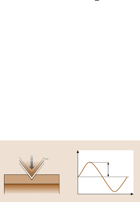
Figure 16.13 shows the schematic of a fatigue test on a coating/substrate sys-
tem using a continuous stiffness measurement (CSM) technique. Load cycles are
applied to the coating, resulting in cyclic stress. P is the cyclic load, P
mean
is the
mean load, P
o
is the oscillation load amplitude, and ω is the oscillation frequency.
P(t)=P
mean
+P
0
sin(ωt)
Substrate
Indenter
motion
t
P(t)
P
0
P
mean
Fig. 16.13. Schematic of a fatigue test on a coating/substrate system using the continuous
stiffness measurement technique
16 Nanotribology of Amorphous Carbon Films 871
The following results can be obtained: (1) endurance limit (the maximum load be-
low which there is no coating failure for a preset number of cycles); (2) number
of cycles at which the coating failure occurs; and (3) changes in contact stiffness
(measured using the unloading slope of each cycle), which can be used to monitor
the propagation of interfacial cracks during a cyclic fatigue process.
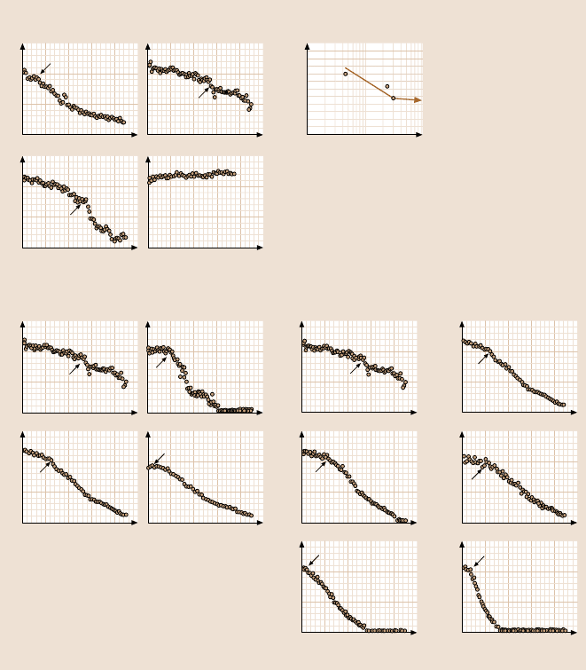
Figure 16.14a shows the contact stiffness as a function of the number of cycles
for 20 nm-thick FCA coatings cyclically deformed by various oscillation load am-
plitudes with a mean load of 10µN at a frequencyof 45 Hz. At 4 µN load amplitude,
no change in contact stiffness was found for all coatings. This indicates that 4 µN
load amplitude is not high enough to damage the coatings. At 6 µN load amplitude,
an abrupt decrease in contact stiffness was found after a certain number of cycles
for each coating, indicating that fatigue damage had occurred. With increasing load
amplitude, the number of cycles to failure, N
f
, decreases for all coatings. Load am-
plitude versus N
f
, a so-called S–N curve, is plotted in Fig. 16.14b. The critical load
amplitude below which no fatigue damage occurs (an endurance limit), was identi-
fied for each coating. This critical load amplitude, together with the mean load, are
of critical importance to the design of head-disk interfaces or MEMS/NEMS device
interfaces.
To compare the fatigue lives of the different coatings studied, the contact stiff-
ness is shown as a function of the number of cycles for 20nm-thick FCA, IB, ECR-
CVD and SP coatings cyclically deformed by an oscillation load amplitude of 8µN
with a mean load of 10 µN at a frequency of 45 Hz in Fig. 16.14c. The FCA coat-
ing has the largest N
f
, followed by the ECR-CVD, IB and SP coatings. In addition,
after N
f
, the contact stiffness of the FCA coating shows a slower decrease than
the other coatings. This indicates that the FCA coating was less damaged than the
others after N
f
. The fatigue behaviors of FCA and ECR-CVD coatings of different
thicknesses are compared in Fig. 16.14d. For both coatings, N
f
decreases with de-
creasing coating thickness. At 10nm, FCA and ECR-CVD have almost the same
fatigue life. At 5 nm, the ECR-CVD coating shows a slightly longer fatigue life
than the FCA coating. This indicates that the microstructure and residual stresses
are not uniform across the thickness direction, even for nanometer-thick DLC coat-
ings. Thinner coatings are more influenced by interfacial stresses than thicker coat-
ings.
Figure16.15a showshigh-magnificationSEM images of 20 nm-thick FCA coat-
ingsbefore,at, and after N
f
. In the SEM images, the net-like structure is thegold film
coatedon the DLC coating,whichshould be ignoredwhen analyzingthe indentation
fatigue damage. Before N
f
, no delamination or buckling was found except for the
residual indentation mark at magnifications of up to 1,200,000× using SEM. This
suggests that only plastic deformationoccurred before N
f
.AtN
f
, the coating around
the indenter bulged upwards, indicating delamination and buckling. Therefore, it is
believed that the decrease in contact stiffness at N
f
results from delamination and
buckling of the coating from the substrate. After N
f
, the buckled coating was broken
down around the edge of the buckled area, forming a ring-like crack. The remaining
coating overhungat the edge of the buckled area. It is noted that the indentation size
872 Bharat Bhushan
15
10
5
0
15
10
5
0
012345012345
15
10
5
0
10
3
2
10
4
10
5
34567 2 34 67
15
10
5
0
15
10
5
0
012345012345
15
10
5
0
15
10
5
0
15
10
5
0
15
10
5
0
15
10
5
0
15
10
5
0
012345 012345
5
a)
Contact stiffness (10
3
N/m)
FCA
Load amplitude=10μN Load amplitude= 8μN
Load amplitude=6 μN
Number of cycles (× 10
4
)
Load amplitude= 4μN
N
f
N
f
N
f
b)
FCA
Load amplitude μN
N
f
(cycles)
c)
Contact stiffness (10
3
N/m)
FCA
Number of cycles (× 10
4
)
N
f
N
f
N
f
IB
SP
ECR–CVD
N
f
Contact stiffness (10
3
N/m)
20 nm
N
f
FCA ECR–CVD
Contact stiffness (10
3
N/m)
N
f
20 nm
10 nm
N
f
N
f
10 nm
5 nm
N
f
N
f
5nm
Number of cycles (× 10
4
) Number of cycles (× 10
4
)
d)
Fig. 16.14. (a) Contact stiffness as a function of the number of cycles for 20 nm-thick FCA
coatings cyclically deformed by various oscillation load amplitudes with a mean load of
10 µN at a frequency of 45 Hz; (b) plot of load amplitude versus N
f
;(c) contact stiffness
as a function of the number of cycles for four different 20 nm-thick coatings with a mean
load of 10 µN and a load amplitude of 8 µN at a frequency of 45 Hz; and (d) contact stiffness
as a function of the number of cycles for two coatings of different thicknesses at a mean load
of 10 µN and a load amplitude of 8 µN at a frequency of 45 Hz
increases with the number of cycles. This indicates that deformation, delamination
and buckling as well as ring-like crack formation occurred over a period of time.
The schematic in Fig. 16.15b shows various stages of indentation fatigue dam-
age for a coating/substrate system. Based on this study, three stages of indentation
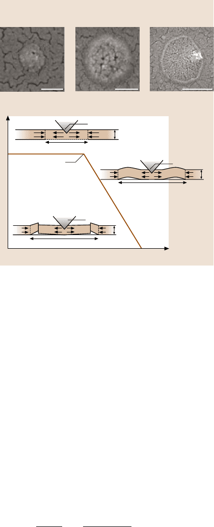
16 Nanotribology of Amorphous Carbon Films 873
200 nm 200 nm 500 nm
20 nm FCA
Stage 1, before N
f
Stage 2, at N
f
Stage 3, after N
f
a)
b)
Contact stiffness (N/m)
Number of cycles
Stage 1
Indentation induced
compression
Stage 3
Ring-like crack
formation
Stage 2
Delamination
and buckling
Failure
N
f
V
i
2a
V
i
2a
V
i
2a
σ
i
σ
r
σ
i
σ
r
t
t
σ
i
σ
r
t
Fig. 16.15. (a) High-
magnification SEM images
of a coating before, at, and
after N
f
,and(b) schematic of
various stages of indentation
fatigue damage for a coat-
ing/substrate system [90]
fatigue damage appear to exist: (1) indentation-inducedcompression; (2) delamina-
tion and buckling; (3) ring-like crack formation at the edge of the buckled coating.
The depositionprocess often inducesresidual stresses in coatings.The model shown
in Fig. 16.15b considers a coating with uniform biaxial residual compression σ
r
.In
the first stage, indentation induces elastic/plastic deformation, exerting a pressure
(acting outward) on the coating around the indenter. Interfacial defects like voids
and impurities act as original cracks. These cracks propagate and link up as the in-
dentation compressive stress increases. At this stage, the coating, which is under
the indenter and above the interfacial crack (with a crack length of 2a), still main-
tains a solid contact with the substrate; the substrate still fully supports the coating.
Therefore, this interfacial crack does not lead to an abrupt decrease in contact stiff-
ness, but gives rise to a slight decrease in contact stiffness, as shown in Fig. 16.14.
The coating above the interfacial crack is treated as a rigidly clamped disk. We as-
sume that the crack radius, a, is large compared with the coating thickness t.Since
the coating thickness ranges from 5 to 20nm, this assumption is easily satisfied in
this study (the radius of the delaminated and buckled area, shown in Fig. 16.15a,
is on the order of 100nm). The compressive stress caused by indentation is given
as [97]:
σ
i
=
E
(1−ν)
ε
i
=
EV
i
2πta
2
(1−ν)
, (16.3)

874 Bharat Bhushan
where ν and E are the Poisson ratio and elastic modulus of the coating, V
i
is the
indentation volume, t is the coating thickness, and a is the crack radius. As the
number of cycles increases, so does the indentation volume V
i
. Therefore, the in-
dentation compressive stress σ
i
increases accordingly. In the second stage, buckling
occurs during the unloading segment of the fatigue testing cycle when the sum of
the indentation compressive stress σ
i
and the residual stress σ
r
exceed the critical
buckling stress σ
b
for the delaminated circular section, as given by [98]
σ
b
=
μ
2
E
12
,
1−ν
2
-
t
a
2
, (16.4)
where the constant μ equals 42.67 for a circular clamped plate with a constrained
center point and 14.68 when the center is unconstrained. The buckled coating acts
as a cantilever. In this case, the indenter indents a cantilever rather than a coat-
ing/substratesystem. This ultrathin coating cantileverhas muchless contactstiffness
than the coating/substrate system. Therefore, the contact stiffness shows an abrupt
decrease at N
f
. In the third stage, with more cycles, the delaminated and buckled
size increases, resulting in a further decrease in contact stiffness since the cantilever
beam length increases. On the other hand, a high bending stress acts at the edge
of the buckled coating. The larger the buckled size, the higher the bending stress.
The cyclic bending stress causes fatigue damage at the end of the buckled coating,
forming a ring-like crack. The coating under the indenter is separated from the bulk
coating (caused by the ring-like crack at the edge of the buckled coating) and the
substrate (caused by the delamination and buckling in the second stage). Therefore,
the coating underthe indenter is not constrained; it is free to move with the indenter
during fatigue testing. At this point, the sharp nature of the indenter is lost, because
the coating under the indenter gets stuck on the indenter. The indentation fatigue
experiment results in the contact of a (relatively) huge blunt tip with the substrate.
This results in a low contact stiffness value.
Compressive residual stresses result in delamination and buckling. A coating
with a higher adhesion strength and a lower compressive residual stress is required
for a higher fatigue life. Interfacial defects should be avoided in the coating depo-
sition process. We know that ring-like crack formation occurs in the coating. For-
mation of fatigue cracks in the coating depends upon the hardness and the fracture
toughness.Cracksare moredifficult to form and propagate inthe coatingwith higher
strength and fracture toughness.
It is now accepted that long fatigue life in a coating/substrate almost always
involves“living with a crack”, that the threshold or limit condition is associated with
the nonpropagation of existing cracks or defects, even though these cracks may be
undetectable [96]. For all of the coatings studied at 4µN, the contact stiffness does
not changemuch. This indicates thatdelaminationand bucklingdid not occurwithin
the number of cycles tested in this study. This is probably because the indentation-
induced compressive stress was not high enough to allow the cracks to propagate
and link up under the indenter, or the sum of the indentation compressive stress σ
i
and the residual stress σ
r
did not exceed the critical buckling stress σ
b
.
16 Nanotribology of Amorphous Carbon Films 875
Figure 16.10 and Table 16.5 summarize the hardnesses, elastic moduli, fracture
toughnesses, and fatigue lifetimes of all of the coatings studied. A good correlation
exists between the fatigue life and other mechanical properties. Higher mechanical
properties result in a longer fatigue life. The mechanical properties of DLC coatings
are controlled by the sp
3
-to-sp
2
ratio. An sp
3
-bonded carbon exhibits the outstand-
ing properties of diamond [51]. Higher kinetic energy during deposition will result
in a larger fraction of sp
3
-bondedcarbon in an amorphousnetwork. Thus,the higher
kinetic energy for the FCA could be responsible for its enhanced carbon structure
and mechanical properties [48–50,99]. Higher adhesion strength between the FCA
coating and substrate makes the FCA coating more difficult to delaminate from the
substrate.
16.4.2 Microscratch and Microwear Studies
For microscratch studies, a conical diamond indenter (that has a tip radius of about
one micron and a cone angle of 60
◦
for example) is drawn over the sample surface,
and the load is ramped up (typically from 2 mN to 25mN) until substantial damage
occurs. The coefficient of friction is monitored during scratching. Scratch-induced
coating damage, specifically fracture or delamination, can be monitored by in situ
friction force measurements and using optical and SEM imaging of the scratches
after tests. A gradual increase in friction is associated with plowing, and an abrupt
increase in friction is associated with fracture or catastrophic failure [100]. The
load corresponding to an abrupt increase in friction or an increase in friction above
a certain value (typically 2× the initial value) provides a measure of the scratch
resistance or the adhesive strength of a coating, and is called the “critical load”.
The depths of scratches are measured with increasing scratch length or normal load
using an AFM, typically with an area of 10×10µm [48,49,101].
Microscratch and microwear studies are also conducted using an AFM [23,50,
99,102,103].A square pyramidaldiamond tip (tip radius ≈ 100nm) or a three-sided
pyramidal diamond (Berkovich) tip with an apex angle of 60
◦
and a tip radius of
about 100nm, mounted on a platinum-coated, rectangular stainless steel cantilever
of stiffness of about 40 N/m, is scanned orthogonalto the long axis of the cantilever
to generate scratch andwear marks. Duringthe scratch test, the normal load is either
keptconstantor isincreased(typicallyfrom0 to 100µN)untildamage occurs.Topo-
graphical images of the scratch are obtained in situ with the AFM at a low load. By
scanning the sample during scratching, wear experiments can be conducted. Wear
is monitored as a function of the number of cycles at a constant load. Normal loads
(10–80 µN) are typically used.
Microscratch
Scratch tests conducted with a sharp diamond tip simulate a sharp asperity contact.
In a scratch test, the cracking or delamination of a hard coating is signaled by a sud-
den increase in the coefficient of friction [23]. The load associated with this event is
called the “critical load”.
876 Bharat Bhushan
1
0.8
0.6
0.4
0.2
0
01234
0
5.0
10.0
0
5.0
10.0
15.0
1
0.8
0.6
0.4
0.2
0
01234
300
200
100
0
0
5.0
10.0
0
5.0
10.0
15.0
1
0.8
0.6
0.4
0.2
0
01234
0
5.0
10.0
15.0
μm
0
5.0
10.0
15.0
1
0.8
0.6
0.4
0.2
0
01234
300
200
100
0
0
5.0
0
5.0
10.0
15.0
1
0.8
0.6
0.4
0.2
0
01234
0
5.0
10.0
0
5.0
10.0
15.0
1
0.8
0.6
0.4
0.2
0
01234
300
200
100
0
0
5.0
10.0
0
5.0
10.0
15.0
1
0.8
0.6
0.4
0.2
0
01234
300
200
100
0
0
5.0
10.0
0
5.0
10.0
15.0
1
0.8
0.6
0.4
0.2
0
01234
0
5.0
10.0
0
1
0.8
0.6
0.4
0.2
0
01234
300
200
100
0
0
5.0
10.0
0
5.0
10.0
15.0
1
0.8
0.6
0.4
0.2
0
01234
0
5.0
10.0
0
5.0
10.0
15.0
1
0.8
0.6
0.4
0.2
0
01
234
300
200
100
0
0
5.0
10.0
0
5.0
10.0
15.0
1
0.8
0.6
0.4
0.2
0
01234
0
5.0
10.0
0
5.0
10.0
15.0
1
0.8
0.6
0.4
0.2
0
01234
300
200
100
0
0
5.0
10.0
0
5.0
10.0
15.0
1
0.8
0.6
0.4
0.2
0
1234
0
5.0
10.0
0
5.0
10.0
15.0
1
0.8
0.6
0.4
0.2
0
01234
300
200
100
0
0
5.0
10.0
0
5.0
10.0
15.0
1
0.8
0.6
0.4
0.2
0
01234
15.0
μm
15.0μm
15.0μm
15.0μm
15.0μm
15.0μm
15.0μm
FCA
a) b)
IB
Coefficient of friction
Coefficient of friction
Coefficient of friction
Coefficient of friction
Normal load (mN)
Coefficient of friction
Coefficient of friction
Coefficient of friction
Coefficient of friction
Normal load (mN)
Coefficient of friction
Normal load (mN)
Coefficient of friction
Normal load (mN)
Normal load (mN)
Normal load (mN)
Normal load (mN)
Normal load (mN)
Scratch
direction
Normal load (mN)
nm
nm
nm
nm
nm
nm
nm
nm
20 nm
10 nm
5 nm
3.5 nm
20 nm
10 nm
5 nm
3.5 nm
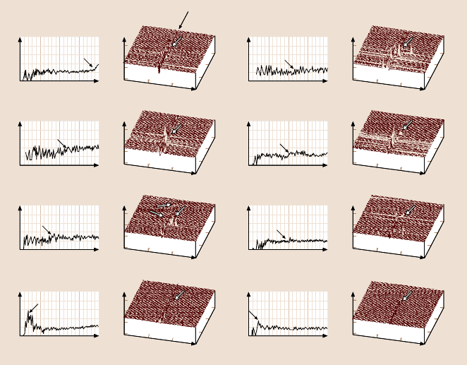
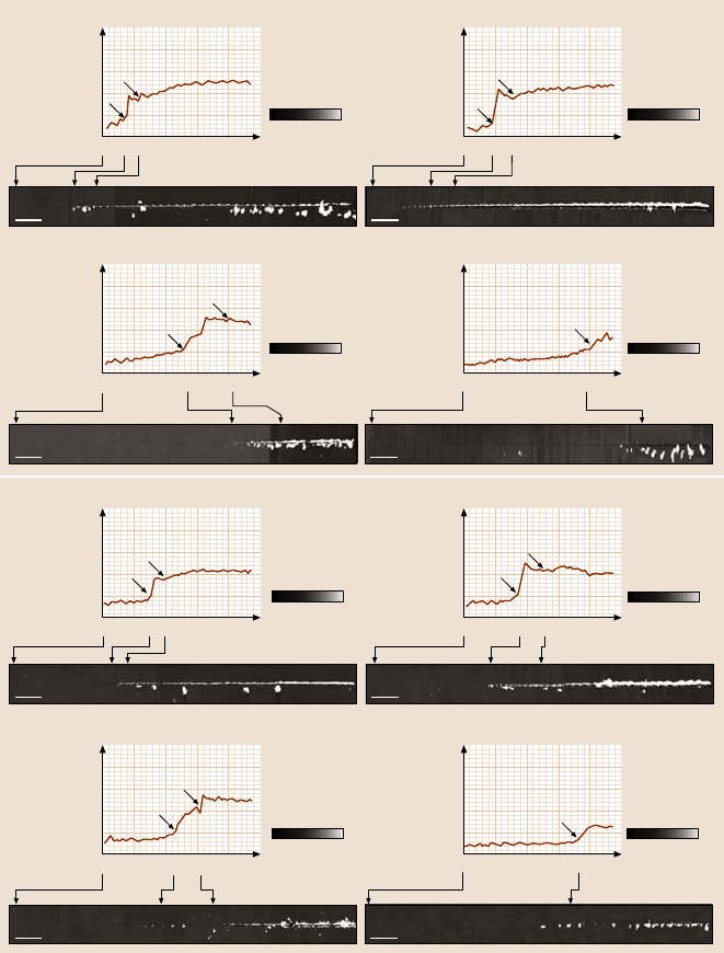
Fig. 16.16a,b. Coefficient of friction profiles as a function of normal load, as well as corre-
sponding AFM surface height maps of regions over scratches at the respective critical loads
(indicated by the arrows in the friction profiles and AFM images), for coatings of different
thicknesses deposited by various deposition techniques: (a)FCA,(b)IB
Wu [104], Bhushan et al. [70], Gupta and Bhushan [12, 47], and Li and Bhu-
shan [48,49, 101] have used a nanoindenter to perform microscratch (mechanical
durability) studies of various carbon coatings. The coefficient of friction profiles as
a function of increasing normal load as well as AFM surface height maps of re-
gions over scratches at the respective critical loads (indicated by the arrows in the
friction profiles and AFM images) observed for coatings with different thicknesses
and single-crystal silicon substrate using a conical tip are compared in Figs. 16.16
and 16.17. Bhushan and Koinkar [102], Koinkar and Bhushan [103], Bhushan [23],
and Sundararajanand Bhushan[50,99] used an AFM to perform microscratchstud-
ies. Data obtained for coatings with different thicknesses and silicon substrate using
a Berkovich tip are compared in Figs. 16.18 and 16.19. Critical loads for various
coatings tested using a nanoindenter and AFM are summarized in Fig. 16.20. Se-
lected data for 20nm-thick coatings obtained using nanoindenter are also presented
in Fig. 16.10 and Table 16.5.
It is clear that a well-defined critical load exists for each coating. The AFM im-
ages clearly show that below the critical loads the coatings were plowed by the
scratch tip, associated with the plastic flow of materials. At and after the criti-
16 Nanotribology of Amorphous Carbon Films 877
1
0.8
0.6
0.4
0.2
0
034
300
200
100
0
0
5.0
10.0
0
5.0
10.0
15.0
1
0.8
0.6
0.4
0.2
0
01 2
0
5.0
10.0
0
5.0
10.0
15.0
1
0.8
0.6
0.4
0.2
0
300
200
100
0
0
5.0
10.0
15.0
μm
0
5.0
10.0
15.0
1
0.8
0.6
0.4
0.2
0
0
5.0
10.0
0
5.0
10.0
15.0
1
0.8
0.6
0.4
0.2
0
300
200
100
0
0
5.0
10.0
0
5.0
10.0
15.0
1
0.8
0.6
0.4
0.2
0
0
5.0
10.0
0
5.0
10.0
15.0
1
0.8
0.6
0.4
0.2
0
300
200
100
0
0
5.0
10.0
0
5.0
10.0
15.0
1
0.8
0.6
0.4
0.2
0
0
5.0
10.0
0
1
0.8
0.6
0.4
0.2
0
01234
300
200
100
0
0
5.0
10.0
0
5.0
10.0
15.0
1
0.8
0.6
0.4
0.2
0
01234
0
5.0
10.0
0
5.0
10.0
15.0
1
0.8
0.6
0.4
0.2
0
01234
300
200
100
0
0
5.0
10.0
0
5.0
10.0
15.0
1
0.8
0.6
0.4
0.2
0
01
2
34
0
5.0
10.0
0
5.0
10.0
15.0
1
0.8
0.6
0.4
0.2
0
01234
300
200
100
0
0
5.0
10.0
0
5.0
10.0
15.0
1
0.8
0.6
0.4
0.2
0
1234
0
5.0
10.0
0
5.0
10.0
15.0
15.0
μm
15.0μm
15.0μm
15.0μm
15.0μm
15.0μm
56
3401 2 56
3401 2 56
3401 2 56
Coefficient of friction
Coefficient of friction
Coefficient of friction
Coefficient of friction
Normal load (mN)
Coefficient of friction
Coefficient of friction
Coefficient of friction
ECR–CVD
Coefficient of friction
Normal load (mN)
Coefficient of friction
Normal load (mN)
Normal load (mN)
Normal load (mN)
Normal load (mN)
Normal load (mN)
c) d)
Normal load (mN)
nm
nm
nm
nm
nm
nm
nm
20 nm
10 nm
5 nm
3.5 nm
20 nm
10 nm
5 nm
SP
Fig. 16.16c,d. Coefficient of friction profiles as a function of normal load, as well as corre-
sponding AFM surface height maps of regions over scratches at the respective critical loads
(indicated by the arrows in the friction profiles and AFM images), for coatings of different
thicknesses deposited by various deposition techniques: (c) ECR-CVD, (d)SP
1
0.8
0.6
0.4
0.2
0
034
300
200
100
0
0
5.0
10.0
0
5.0
10.0
15.0
012
15.0
μm
Coefficient of friction
Normal load (mN)
nm
Si(100)
Scratch direction
Fig. 16.17. Coefficient of friction profiles as a function of normal load as well as corre-
sponding AFM surface height maps of regions over scratches at the respective critical loads
(indicated by the arrows in the friction profiles and AFM images) for Si(100)
cal loads, debris (chips) or buckling was observed on the sides of the scratches.
Delamination or buckling can be observed around or after the critical loads, which
suggests that the damage starts from delamination and buckling. For the 3.5- and
5 nm-thick FCA coatings, before the critical loads small debris is observed on the
sidesof the scratches.Thissuggeststhat thethinnerFCA coatingsare not sodurable.
878 Bharat Bhushan
0.5
0.4
0.3
0.2
0.1
0.0
0 25 50 75 100 125
0.5
0.4
0.3
0.2
0.1
0.0
0 25 50 75 100 125
0.5
0.4
0.3
0.2
0.1
0.0
0 25 50 75 100 125
0.5
0.4
0.3
0.2
0.1
0.0
0 25 50 75 100 125
a)
0nm
20nm
0nm
20nm
0nm
20nm
0nm
20nm
Coefficient of friction
Coefficient of friction Coefficient of friction
Normal load
(μN)
Coefficient of friction
FCA
3.5 nm
FCA
5 nm
FCA
20 nm
FCA
10 nm
A
B
A
B
A
B
A
Normal load
(μN)
Normal load
(μN)
Normal load
(μN)
2μm 2μm
2μm2μm
0.5
0.4
0.3
0.2
0.1
0.0
0 25 50 75 100 125
0.5
0.4
0.3
0.2
0.1
0.0
0 25 50 75 100 125
0.5
0.4
0.3
0.2
0.1
0.0
0 25 50 75 100 125
0.5
0.4
0.3
0.2
0.1
0.0
0 25 50 75 100 125
Coefficient of friction
Coefficient of friction Coefficient of friction
Coefficient of friction
ECR–CVD
3.5 nm
A
B
A
B
A
B
A
ECR–CVD
5 nm
ECR–CVD
10 nm
ECR–CVD
20 nm
b)
Normal load
(μN)
Normal load
(μN)
Normal load
(μN)
Normal load
(μN)
2μm
0nm
20nm
2μm
0nm
20nm
2μm
0nm
20nm
2μm
0nm
20nm
Fig. 16.18. Coefficient of friction profiles during scratch as a function of normal load and
corresponding AFM surface height maps for (a)FCA,(b) ECR-CVD
It is obvious that, for a given deposition method, the critical loads increase with in-
creasing coating thickness. This indicates that the critical load is determined not
only by the strength of adhesion to the substrate, but also by the coating thickness.
We note that more debris generated on the thicker coatings than thinner coatings.
