Bhushan B. Nanotribology and Nanomechanics: An Introduction
Подождите немного. Документ загружается.

16 Nanotribology of Amorphous Carbon Films 859
2,500
2,000
1,500
1,000
500
0
1,0001,2001,4001,6001,800
Intensity (counts)
Raman shift (cm
–1
)
800
600
400
200
0
1,0001,2001,4001,6001,800
Intensity (counts)
Raman shift (cm
–1
)
700
600
500
400
300
200
100
0
1,0001,2001,4001,6001,800
Intensity (counts)
Raman shift (cm
–1
)
1,400
1,200
1,000
800
600
400
200
0
1,0001,2001,4001,6001,800
Intensity (counts)
Raman shift (cm
–1
)
4,000
3,500
3,000
2,500
2,000
1,500
1,000
1,0001,2001,4001,6001,800
Intensity (counts)
Raman shift (cm
–1
)
800
600
400
200
0
1,0001,2001,4001,6001,800
Intensity (counts)
Raman shift (cm
–1
)
6,000
5,000
4,000
3,000
2,000
1,000
0
1,0001,2001,4001,6001,800
Intensity (counts)
Raman shift (cm
–1
)
Graphite
Diamond
Sputtered a–C (W
1
)
Sputtered a– C (W
2
)
Sputtered a– C:H (H
1
)
Sputtered a– C:H (H
3
)
PECVD a– C:H
MPECVD diamond
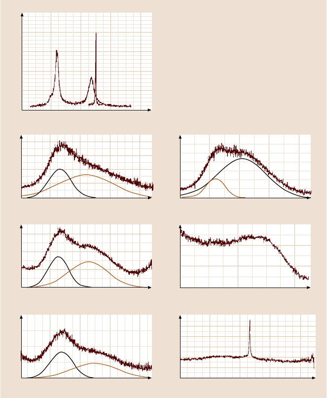
Fig. 16.6. Raman spectra of the DLC coatings produced by DC magnetron sputtering and
RF-PECVD techniques and a diamond film produced by the MPE-CVD technique. Data for
bulk diamond and microcrystalline graphite are included for comparison [35]
16.3.2 Hydrogen Concentrations
A FRS analysis of six sputtered (W2, H2, H3, H4, H5, and H6) coatings, one
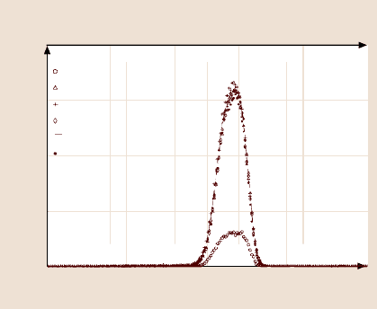
PECVD coating, and one diamond coating was performed. Figure 16.7 shows an
overlay of the spectra from the six sputtered samples. Similar spectra were obtained
from the PECVD and the diamond films. Table 16.3 shows the H and C fractions as
860 Bharat Bhushan
Counts
4,000
3,000
2,000
1,000
0
Energy (MeV)
0
0.0 0.2 0.4 0.6 0.8 1.0
50 100 150 200
Channel
W
2
sputtered 100% Ar
H
2
sputtered 99% Ar/1% H
H
3
sputtered 97% Ar/3% H
H
4
sputtered 95% Ar/5% H
H
5
sputtered 93% Ar/7% H
H
6
sputtered 90 % Ar/10% H
Fig. 16.7. FRS spectra for
six DLC coatings produced
by DC magnetron sputter-
ing [35]
well as the amountof impurities (Ar and O) in the films in atomic %. Most apparent
is the large fraction of H in the sputtered films. Regardless of how much H
2
is in the
Ar sputtering gas, the H content of the coatings is about the same, ≈ 35at. %. In-
terestingly, there is still ≈ 10% H present in the coating sputtered in pure Ar (W2).
It is interesting to note that Ar is present only in coatings grown using Ar carrier
gas with a low (< 1%) H content. The presence of O in the coatings combined with
the fact that the coatings were prepared approximately nine months before the FRS
analysis caused suspicion that they had absorbed water vapor, and that this may be
the cause of the H peak in specimen W2.
All samples were annealed for 24h at 250
◦
C in a flowing He furnace and then
reanalyzed. Surprisingly, the H contents of all coatings measured increased slightly,
even though the O content decreased, and W2 still had a substantial amount of H
2
.
This slight increase in H concentration is not understood. However, the fact that the
H concentration did not decrease with the oxygen as a result of annealing suggests
that high H concentration is not due to adsorbed water vapor. The PECVD film has
more H (≈18%) than the sputtered films initially, but after annealing it has the same
fraction as specimen W2, the film sputtered in pure Ar. The diamond film has the
smallest amount of hydrogen, as seen in Table 16.3.
16.3.3 Physical Properties
The physical properties of the four sputtered (W1, W2, H1, and H3) coatings, one
PECVDcoating, onediamondcoating, andbulkdiamond andgraphite arepresented
in Table 16.4. The hydrogenated carbon and the diamond coatings have very high
resistivity compared to unhydrogenated carbon coatings. It appears that unhydro-
genated carbon coatings have higher densities than hydrogenated carbon coatings,
although both groups are less dense than graphite. The density depends upon the
deposition technique and the deposition parameters. It appears that unhydrogenated
sputteredcoatingsdepositedat lowpowerexhibitthe highestdensity. Thenanohard-
16 Nanotribology of Amorphous Carbon Films 861
nessof hydrogenatedcarbon is somewhatlowerthan thatof unhydrogenatedcarbon.
PECVD coatings are significantly harder than sputtered coatings. The nanohardness
and modulus of elasticity of a diamond coating is very high compared to that of
a DLC coating, even though the hydrogen contents are similar. The compressive
residual stresses of the PECVD coatings are substantially higher than those of sput-
tered coatings, which is consistent with the results for the hardness.
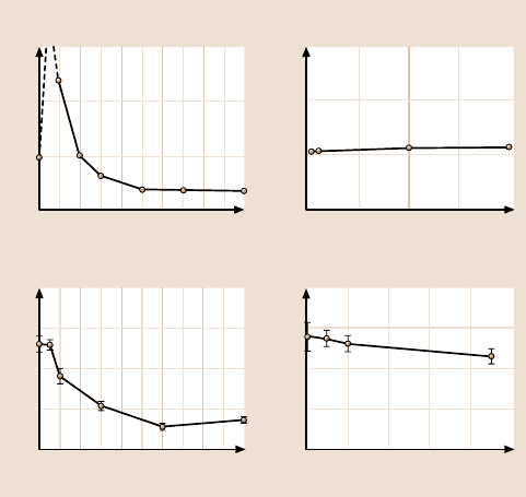
Figure 16.8a shows the effect of hydrogen in the plasma on the residual stresses
and the nanohardness for the sputtered coatings W2 and H1 to H6. The coatings
made with a hydrogen flow of between 0.5 and 1.0% delaminate very quickly, even
when theyare only a few tens of nm thick.In pure Ar and at H
2
flowsthat are greater
than 1%, the coatings appear to be more adhesive. The tendency of some coatings
to delaminate can be caused by intrinsic stress in the coating, which is measured
by substrate bending. All of the coatings in the figure are in compressive stress.
The maximum stress occurs between 0 and 1% H
2
flow, but the stress cannot be
quantified in this range because the coatings instantly delaminate upon exposure to
air. At higher hydrogen concentrations the stress gradually diminishes. A generally
decreasingtrend is observedfor the hardnessof the coatingsas the hydrogencontent
is increased. The hardness decreases slightly, going from 0% H
2
to 0.5% H
2
,and
then decreasessharply. These resultsare probablylower than thetrue valuesbecause
of local delamination around the indentation point. This is especially likely for the
1.5
1.0
0.5
0.0
0246810
20
15
10
5
0
0246810
1.5
1.0
0.5
0.0
0 50 100 150 200
20
15
10
5
0
0 100 200 300 400 500
Compressive stress (GPa)
Sputtering power (W)
Compressive stress (GPa)
Hydrogen flow (%)
a) b)
Hardness (GPa)
Hydrogen flow (%)
Sputtering power (W)
Hardness (GPa)
Fig. 16.8. Residual compressive stresses and nanohardness (a) as a function of hydrogen flow
rate, where the sputtering power is 100 W and the target diameter is 75 mm (power density
= 2.1W/cm
2
), and (b) as a function of sputtering power over a 75 mm diameter target with
no hydrogen added to the plasma [40]
862 Bharat Bhushan
0.5% and 1.0% coatings, where delamination is visually apparent, but may also
be true to a lesser extent for the other coatings. Such an adjustment would bring the
hardness profile into closer correlation with the stress profile. Weissmantel et al. [68]
and Scharff et al. [85] observed a downturn in hardness for high bias and a low
hydrocarbon gas pressure for ion-plated carbon coating, and, therefore, presumably
low hydrogen content in support of the above contention.
Figure 16.8b shows the effect of sputtering power (with no hydrogen added to
the plasma) on theresidual stresses and nanohardnessfor varioussputteredcoatings.
As the power decreases, the compressive stress does not seem to change while the
nanohardness slowly increases. The rate of change becomes more rapid at very low
power levels.
The addition of H
2
during sputtering of the carbon coatings increases the H con-
centration in the coating. Hydrogen causes the character of the C–C bonds to shift
from sp
2
to sp
3
, and a rise in the number of C–H bonds, which ultimately relieves
stress and producesa softer “polymer-like”material. Low power deposition,like the
presence of hydrogen, appears to stabilize the formation of sp
3
C–C bonds, increas-
ing hardness. These coatings relieve stress and lead to better adhesion. Increasing
the temperature during deposition at high power density results in graphitization of
the coating material, producing a decrease in hardness with an increase in power
density. Unfortunately, low power also means impractically low deposition rates.
16.3.4 Summary
Based on analyses of EELS and Raman data, it is clear that all DLC coatings have
both sp
2
and sp
3
bonding characteristics. The sp
2
/sp
3
bonding ratio depends upon
the deposition techniqueand parameters used. DLC coatingsdepositedbysputtering
and PECVD contain significant concentrations of hydrogen, while diamond coat-
ings contain only small amounts of hydrogenimpurities. Sputtered coatings with no
deliberate addition of hydrogen in the plasma contain a significant amount of hy-
drogen. Regardless of how much hydrogen is in the Ar sputtering gas, the hydrogen
content of the coatings increases initially but then does not increase further.
Hydrogen flow and sputtering power density affect the mechanical properties of
these coatings. Maximum compressive residual stress and hardness occur between
0 and 1% hydrogen flow, resulting in rapid delamination. Low sputtering power
moderately increases hardness and also relieves residual stress.
16.4 Micromechanical and Tribological Coating
Characterization
16.4.1 Micromechanical Characterization
Common mechanical characterizationsinclude measurements of hardness and elas-
tic modulus, fracture toughness, fatigue life, and scratch and wear testing. Nanoin-
dentation and atomic force microscopy (AFM) are used for the mechanical charac-
terization of ultrathin films.
16 Nanotribology of Amorphous Carbon Films 863
Hardness and elastic modulus are calculated from the load displacement data
obtainedby nanoindentationat loadsof typically0.2 to 10mN using a commercially
available nanoindenter [23,86]. This instrument monitors and records the dynamic
load and displacement of the three-sided pyramidal diamond (Berkovich) indenter
during indentation. For fracture toughness measurements of ultrathin films 100nm
to a few µm thick, a nanoindentation-based technique is used in which through-
thickness cracking in the coating is detected from a discontinuity observed in the
load–displacement curve, and the energy released during the cracking is obtained
from the curve [87–89]. Based on the energy released, fracture mechanics analysis
is then used to calculate the fracture toughness. An indenter with a cube-corner tip
geometry is preferred because the through-thickness cracking of hard films can be
accomplished at lower loads. In fatigue measurement, a conical diamond indenter
with a tip radius of about one micron is used and load cycles with sinusoidal shapes
are applied [90,91]. The fatigue behavior of a coating is studied by monitoring the
change in contact stiffness, which is sensitive to damage formation.
Hardness and Elastic Modulus
For materials that undergo plastic deformation, high hardness and elastic modulus
are generally needed for low friction and wear, whereas for brittle materials, high
fracture toughness is needed [2, 3,21]. The DLC coatings used for many applica-
tions are hard and brittle, and values of hardness and fracture toughness need to be
optimized.
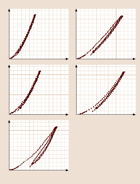
Representative load–displacement plots of indentations made at 0.2mN peak
indentation load on 100 nm-thick DLC coatings deposited by the four deposition
techniques on a single-crystal silicon substrate are compared in Fig. 16.9. The in-
dentation depths at the peak load range from about 18 to 26nm, smaller than that of
the coating thickness. Many of the coatings exhibit a discontinuity or pop-in marks
in the loading curve, which indicate a sudden penetration of the tip into the sample.
A nonuniformpenetration of the tip into a thin coating possibly results from forma-
tion of cracks in the coating, formation of cracks at the coating–substrate interface,
or debonding or delamination of the coating from the substrate.
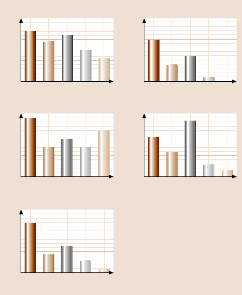
The hardness and elastic modulus values for a peak load of 0.2mNonthevar-
ious coatings and single-crystal silicon substrate are summarized in Table 16.5 and
Fig.16.10 [47,49,89,90].Typicalvaluesfor thepeak and residualindentationdepths
rangefrom18to26nmand6to12nm,respectively. The FCA coating exhibits the
greatest hardness of 24GPa and the highest elastic modulus of 280GPa of the vari-
ous coatings, followed by the ECR-CVD, IB and SP coatings. Hardness and elastic
modulus have been known to vary over a wide range with the sp
3
-to-sp
2
bonding
ratio, which depends on the kinetic energy of the carbon species and the amount
of hydrogen [6,30,47, 92,93]. The high hardness and elastic modulus of the FCA
coatings are attributed to the high kinetic energy of the carbon species involved in
the FCA deposition [12,47]. Anders et al. [57] also reported a high hardness, meas-
ured by nanoindentation, of about 45 GPa for cathodic arc carbon coatings. They
observed a change in hardness from 25 to 45GPa with a pulsed bias voltage and

864 Bharat Bhushan
Table 16.5. Hardness, elastic modulus, fracture toughness, fatigue life, critical load during scratch, coefficient of friction during accelerated wear
testing and residual stress for various DLC coatings on single-crystal silicon substrate
Coating Hardness
a
[48]
(GPa)
Elastic
modulus
a
[48]
(GPa)
Fracture
toughness
a
[89]
(MPam
1/2
)
Fatigue life
b
,
N
f
d
[90]
×10
4
Critical load
during scratch
b
[48]
(mN)
Coefficient of fric-
tion during acceler-
ated wear testing
b
[48]
Compressive
residual stress
c
[47]
(GPa)
Cathodic arc
carbon coating
(a-C)
24 280 11.8 2.0 3.8 0.18 12.5
Ion beam
carbon coating
(a-C:H)
19 140 4.3 0.8 2.3 0.18 1.5
ECR-CVD
carbon coating
(a-C:H)
22 180 6.4 1.2 5.3 0.22 0.6
DC sputtered
carbon coating
(a-C:H)
15 140 2.8 0.2 1.1 0.32 2.0
Bulk graphite
(forcomparison)
Very soft 9–15 – – – – –
Diamond
(forcomparison)
80–104 900–1050 – – – – –
Si(100)
substrate
11 220 0.75 – 0.6 0.55 0.02
a
Measured on 100 nm-thick coatings
b
Measured on 20 nm-thick coatings
c
Measured on 400 nm-thick coatings
d
N
f
was obtained for a mean load of 10 µN and a load amplitude of 8 µN
16 Nanotribology of Amorphous Carbon Films 865
0.2
0.1
0
0.2
0.1
0
010
20 30
0.2
0.1
0
010
20 30
Load (mN)
FCA
ECR–CVD
Load (mN)
IB
SP
Displacement (nm)
Si(100)
Displacement (nm)
Fig. 16.9. Load versus displacement plots for various 100 nm-thick amorphous carbon coat-
ings on single-crystal silicon substrate and bare substrate
bias duty cycle. The high hardness of cathodic arc carbon was attributed to the high
percentage (more than 50%) of sp
3
bonding. Savvides and Bell [94] reported an in-
crease in hardness from 12 to 30 GPa and an increase in elastic modulus from 62
to 213GPa with an increase in the sp
3
-to-sp
2
bonding ratio, from 3 to 6, for a C:H
coating deposited by low-energy ion-assisted unbalanced magnetron sputtering of
a graphite target in an Ar-H
2
mixture.
Bhushanet al. [35] reportedhardnesses of about 15and 35GPa and elastic mod-
uli of about 140 and 200GPa, measured by nanoindentation,for a-C:H coatings de-
posited by DC magnetron sputtering and RF-plasma-enhanced chemical vapor de-
position techniques, respectively. The high hardness of RF-PECVD a-C:H coatings
is attributed to a higher concentration of sp
3
bonding than in a sputtered hydro-
genated a-C:H coating. Hydrogen is believed to play a crucial role in the bonding
configuration of carbon atoms by helping to stabilize the tetrahedral coordination
(sp
3
bonding) of carbon species. Jansen et al. [78] suggested that the incorpora-
866 Bharat Bhushan
30
20
10
0
FCA IB ECR–
CVD
SP Si(100)
300
200
100
0
FCA IB ECR–
CVD
SP Si(100)
15
10
5
0
FCA IB ECR–
CVD
SP Si(100)
3
2
1
0
FCA IB ECR–
CVD
SP Si(100)
6
4
2
0
FCA IB ECR–
CVD
SP Si(100)
Hardness (GPa)
Elastic modulus (GPa)
Fracture toughness (MPa m
1/2
)
Fatigue life (×10
4
)
Critical load (mN)
Fig. 16.10. Bar charts summarizing data for various coatings and single-crystal silicon sub-
strate. Hardnesses, elastic moduli, and fracture toughnesses were measured on 100 nm-thick
coatings, and fatigue lifetimes and criticalloads during scratch were measured on 20 nm-thick
coatings
tion of hydrogenefficiently passivates the danglingbonds and saturates the graphitic
bondingto someextent.However,a largeconcentrationof hydrogenin the plasmain
sputter deposition is undesirable. Cho et al. [33] and Rubin et al. [40] observed that
the hardness decreased from 15 to 3 GPa with increased hydrogen content. Bhushan
and Doerner [95] reported a hardness of about 10–20 GPa and an elastic modulus
of about 170GPa, measured by nanoindentation, for 100nm-thick DC magnetron
sputtered a-C:H on the silicon substrate.
Residual stresses measured using a well-known curvature measurement tech-
nique are also presented in Table 16.5. The DLC coatings are under significant
compressive internal stresses. Very high compressive stresses in FCA coatings are
believed to be partly responsible for their high hardness. However, high stresses
result in coating delamination and buckling. For this reason, the coatings that are
thicker than about 1µm have a tendency to delaminate from the substrates.
16 Nanotribology of Amorphous Carbon Films 867
Fracture Toughness
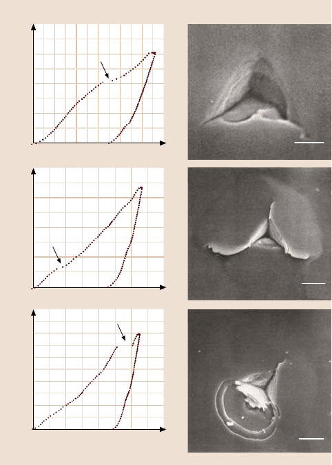
Representative load–displacement curves of indentations on 400nm-thick cathodic
arc carbon coating on silicon for various peak loads are shown in Fig. 16.11. Steps
are found in all of the curves, as shown by arrows in Fig. 16.11a. In the 30 mN SEM
micrograph, in addition to several radial cracks, ring-like through-thickness crack-
ing is observed with small lips of material overhanging the edge of indentation. The
stepsat about 23 mN inthe loadingcurvesof indentationsmade with30 and 100mN
peakindentationloadsresult fromthe ring-likethrough-thicknesscracking. Thestep
at 175mN in the loading curve of the indentation made with 200mN peak indenta-
tion load is caused by spalling and second ring-like through-thickness cracking.
40
30
20
10
0
120
90
60
30
0
250
200
150
100
50
0
Load (mN)
Displacement (nm)
0 100 200 300 400 500 600
4000 800 1,200 1,600
6000 1,200 1,800 2,400
a) b)
30 mN
100 mN
200 mN
2μm
0.5μm
4μm
Fig. 16.11. (a) Load–displacement curves of indentations made with 30, 100, and 200 mN
peak indentation loads using the cube corner indenter, and (b) SEM micrographs of indenta-
tions on a 400 nm-thick cathodic arc carbon coating on silicon. Arrows indicate steps during
the loading portion of the load–displacement curve [87]
868 Bharat Bhushan
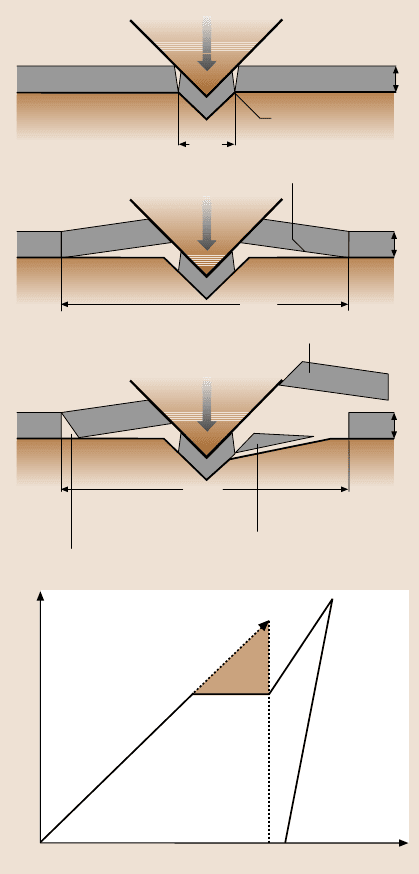
According to Li et al. [87], the fracture process progresses in three stages:
(1) ring-like through-thicknesscracks form around the indenter due to high stresses
in the contact area, (2) delamination and buckling occur around the contact area
at the coating/substrate interface due to high lateral pressure, and (3) second ring-
like through-thickness cracks and spalling are generated by high bending stresses at
the edges of the buckled coating, see Fig. 16.12a. In the first stage, if the coating
Stage 1
2c
R1
First ring-like
through-thickness
crack formation
t
a)
Stage 2
2c
DB
Delamination
and buckling
t
Stage 3
2c
R2
Lateral cracking
during unloading
t
Second ring-like
through-thickness
crack formation
Partial spalling formation
b)
Load (mN)
Displacement (nm)
D
B
C
EF
A
0
Fig. 16.12. (a) Schematic
of various stages in nanoin-
dentation fracture for the
coating/substrate system, and
(b) schematic of a load–
displacement curve showing
a step during the loading cy-
cle and the associated energy
release
