Bhushan B. Nanotribology and Nanomechanics: An Introduction
Подождите немного. Документ загружается.

23 Mechanical Properties of Micromachined Structures 1305
Young’s Modulus Measurements
Young’s modulus, E, is a material property critical to any structural device design.
It describes the elastic response of a material and relates stress, σ,andstrain,ε,by
σ = Eε. (23.5)
In bulk samples, E is often measured by loading a specimen under tension and
measuring displacement as a function of stress for a given length. While this is
far more difficult for small structures, such as those fabricated from thin deposited
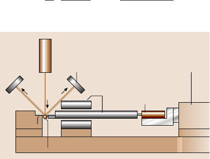
films, it can be achieved with careful experimental techniques. Figure 23.7 shows a
schematic of one such measurement system [15]. The fringe detectors in the figure
detect the reflected laser signal from two gold lines deposited onto the polysilicon
specimen, which act as gauge markers. This enables the strain in the specimen dur-
ing loading to be monitored. Besides gold lines, Vickers indents placed in a nickel
specimen can also serve as gauge markers [16], or a speckle interferometry tech-
nique [17] can be used to determine strain in the specimen. Once the stress-versus-
strain behavior is measured, the slope of the curve is equal to E. By using a constant
load, such as a dead weight, and resistive heating, high-temperature creep can also
be investigated with this method [18].
In addition to the tensile test, Young’s modulus can be determined by other mea-
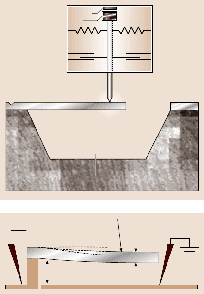
sures of stress–strain behavior. As seen in Fig. 23.8, a cantilever beam can be bent
by pushing on the free end with a nanoindenter [19]. The nanoindenter can moni-
tor the force applied and the displacement, and simple beam theory can convert the
displacement into strain in order to obtain E. A similar technique, shown schemati-
cally in Fig. 23.9 [20], involves pulling downwardon a cantilever beam by means of
an electrostatic force. An electrode is fabricated into the substrate beneath the can-
tilever beam, and a voltage is applied between the beam and the bottom electrode.
The force acting on the beam is equal to the electrostatic force corrected to include
the effects of fringing fields acting on the sides of the beam, namely
F(x) =
ε
0
2
V
g+ z(x)
2
1+
0.65[g+ z(x)]
w
, (23.6)
Fringe
detector
Laser
Air
bearing
Piezoelectric
translator
Load
cell
Grips
Specimen Base
Fig. 23.7. Schematic of
a measurement system for
tensile loading of microma-
chined specimens [15]
1306 Harold Kahn
Identation
marker
AB
Edge of beam
Indenter shaft
Diamond tip
Loading
point
Coil
Capacitance
Gage
Suspending
Magnet
Spring
Si Substrate
C
Fig. 23.8. Schematic of
a nanoindenter loading mech-
anism pushing on the end of
a cantilever beam [19]
θ
0
Gap
V =0V
l
R =1/κ
Fig. 23.9. Schematic of a can-
tilever beam bending test us-
ing an electrostatic voltage
to pull the beam toward the
substrate [20]
where F(x) is the electrostatic force at x, ε
0
is the dielectric constant of air, g is
the gap between the beam and the bottom electrode, z(x) is the out-of-plane deflec-
tion of the beam, w is the beam width, and V is the applied voltage [20]. In this
work, the deflection of the beam as a function of position is measured using optical
interferometry. These measurements combine to give stress–strain behavior for the
cantilever beam. An extension of this technique uses doubly clamped beams instead
of cantilever beams. In this case, the deflection of the beam at a given electrostatic
force dependson the residual stress in the materialas well as Young’smodulus. This
method can therefore also be used to measure residual stresses in doubly clamped
beams.
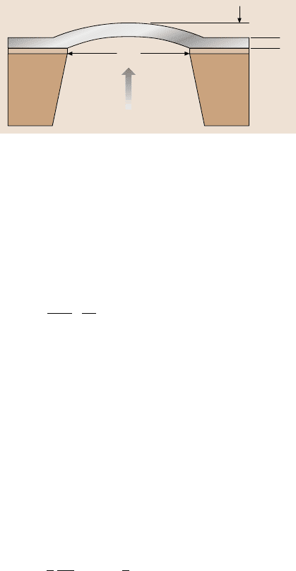
Another device that can be fabricated from a thin film and used to investigate
stress–strain behavior is a suspended membrane, as shown in Fig. 23.10 [21]. As
depicted in the schematic figure, the membrane is exposed to an elevated pressure
on one side, causing it to bulge in the opposite direction. The deflection of the mem-
braneis measuredby optical orother techniquesand relatedto the strain in themem-
brane. These membranes can be fabricated in any shape, typically square or circular.
Both analytical solutions and finite element analyses have been performed to relate
23 Mechanical Properties of Micromachined Structures 1307
2a
d
t
Pressure (p)
Fig. 23.10. Schematic cross-
section of a microfabricated
membrane [21]
the deflection to the strain. Like the doubly clamped beams, both Young’s modulus
and residual stress play a role in the deflected shape. Both of these mechanicalprop-
erties can therefore be determined by the pressure-versus-deflectionperformance of
the membrane.
Another measurementbesides stress–strain behaviorthat can reveal the Young’s
modulus of a material is the determination of the natural resonance frequency. For
a cantilever, the resonance frequency, f
r
, for free undamped vibration is given by
f
r
=
λ
2
i
t
4πl
2
E
3ρ
1/2
, (23.7)
where ρ, l and t are the density, length and thickness of the cantilever; λ
i
is the
eigenvalue, where i is an integer that describes the resonance mode number; for the
firstmode λ
1
= 1.875 [23].Giventhe geometryand density, measuring f
r
allows E to
be determined. The cantilever can be vibrated by a number of techniques, including
a laser, loudspeaker or piezoelectricshaker. The frequencythat producesthe highest
amplitude of vibration is the resonance frequency.
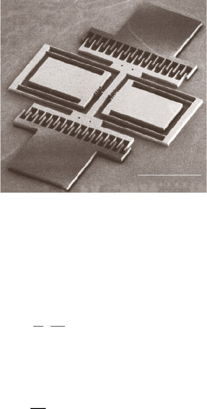
A micromachined device that uses an electrostatic comb drive and an AC signal
to generate the vibration of the structure is known as a lateral resonator [24]. One
example is shown in Fig. 23.11 [22]. When a voltage is applied across either set
of the interdigitated comb fingers shown in Fig. 23.11, an electrostatic attraction is
generateddue to the increase in capacitance as the overlapbetween the comb fingers
increases. The force, F, generated by the comb-driveis given by
F =
1
2
∂C
∂x
V
2
= nε
h
g
V
2
, (23.8)
where C is capacitance, x is the distance traveled by one comb-drive toward the
other, n is the number of pairs of comb fingers in one drive, ε is the permittivity
of the fluid between the fingers, h is the height of the fingers, g is the gap spacing
between the fingers, and V is the applied voltage [24]. When an AC voltage at the
resonance frequency is applied across either of the two comb drives, the central
portion of the device will vibrate. In fact, since force depends on the square of the
voltagefor electrostatic actuation,for a time t, a dependentdrivevoltagev
D
(t)(given
by
v
D
(t) = V
P
+ v
d
sin(ωt) , (23.9)
1308 Harold Kahn
100 μm
Fig. 23.11. SEM of a polysi-
licon lateral resonator [22]
where V
P
is the DC bias and v
d
is the AC drive amplitude), the time-dependent
portion of the force will scale with
2ωV
P
v
d
cos(ωt)+ ωv
2
d
sin(2ωt) (23.10)
[24]. Therefore, if an AC drive signal is used with no DC bias, at resonance, the
frequency of the AC drive signal will be one half of the resonance frequency. For
this device, the resonance frequency f
r
will be
f
r
=
1
2π
k
sys
M
1/2
, (23.11)
where k
sys
is the spring constant of the support beams and M is the mass of the
portion of the device that vibrates. The spring constant is given by
k
sys
= 24EI/L
3
, (23.12)
I =
hw
3
12
, (23.13)
where I is the moment of inertia of the beams, and L, h and w are the length, thick-
ness, and width of each beam. Therefore, by combining these equations and meas-
uring f
r
, it is possible to determine E.
One distinct advantage of the lateral resonator technique and the electrostati-
cally pulled cantilever techniquefor measuringYoung’s modulus is that they require
no external loading sources. Portions of the devices are electrically contacted, and
a voltage is applied. For the pure tension tests, as shown in Fig. 23.7, the specimen
must be attached to a loading system, which can be extremely difficult for the very
small specimens discussed here, and any misalignment or eccentricity in the test

23 Mechanical Properties of Micromachined Structures 1309
could lead to unreliable results. However, the advantage of the externally loaded
technique is that there are no limitations on the type of materials that can be tested.
Conductivity is not a requirement,nor is any compatibilitywith electrical actuation.
Strength and Fracture Toughness Measurements
As one might expect, any of the techniques discussed in the previous section that
strain specimens in order to measure Young’s modulus can also be used to measure
fracture strength.The load is simply increased until the specimen breaks. As long as
either theload or the strainis measuredat fracture, and thegeometryof the specimen
is known, the maximum stress required for fracture σ
crit
can be determined, either
throughanalytical analysisor FEA. Depending on the geometryof the test, σ
crit
will
represent the tensile or bend strength of the material.
If the available force is limited, or if a localized fracture site is desired, stress
concentrations can be added to the specimens. These are typically notches micro-
machined into the edges of specimens. Focused ion beams have also been used to
carve stress concentrations into fracture specimens.
All of the external loading schemes, such as those shown in Figs. 23.7 and 23.8,
have been used to measure fracture strength. Also, the electrostatically loaded dou-
bly clamped beams can be pulled until they fracture. In this case, there is one com-
plication. The electrostatic force is inversely proportional to the distance between
the electrodes, and at a certain voltage, called the “pull-in voltage,” the attraction
between the beam and the substrate will become so great that the beam will imme-
diatelybe pulled intocontact with the bottomelectrode.As long as thefracture takes
place before the pull-in voltage is reached, the experiment will give valid results.
Other loading techniques have been used to generate fracture of microspeci-
mens. Figure 23.12 [25] shows one device designed to be pushed by the end of
a micromanipulatedneedle. The long beams that extendfrom the sides of the central
shuttle come into contact with anchored posts, and, at a critical degree of bending,
the beams will break off. Since the applied force cannot be measured in this tech-
nique, the experiment is continuously optically monitored during the test, and the
image of the beams just before fracture is analyzed to determine σ
crit
.
Another loading scheme that has been demonstrated for micromachined speci-
mens utilizes scratch drive actuators to load the specimens [26]. These types of ac-
a)
b)
c)
Fig. 23.12. (a) SEM of a device for measuring bend strength of polysilicon beams; (b)image
of a test in process; (c) higher magnification view of one beam shortly before breaking [25]
1310 Harold Kahn
tuators work like inchworms, traveling across a substrate in discrete advances as an
electrostatic force is repeatedly applied between the actuator and the substrate. The
stepping motion can be made on the nanometer scale, depending on the frequency
of the applied voltage, and so it can be an acceptable approximation to continuous
loading. One advantage of this scheme is that very large forces can be generated
by relatively small devices. The exact forces generated cannot be measured, so (like
the techniquethat used micromanipulatedpushing)the testis continuouslyobserved
to determine the strain at fracture. Another advantage of this technique is that, like
the lateral resonatorand the electrically pulled cantilever,the loading takes place on-
chip, and therefore the difficulties associated with attaching and aligning an external
loading source are eliminated.
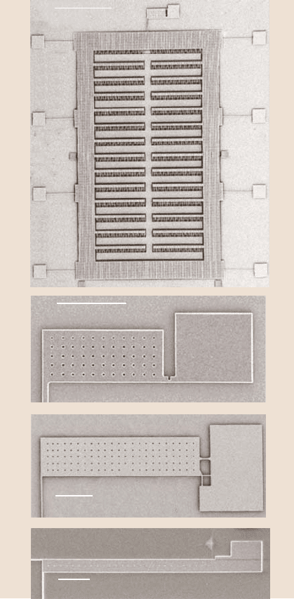
Another on-chip actuator used to load microspecimens is shown in Fig. 23.13,
along with three different microspecimens [14]. Devices have been fabricated with
each of the three microspecimens integrated with the same electrostatic comb-drive
actuator. In all three cases, when a DC voltage is applied to the actuator, it moves
downward, as oriented in Fig. 23.13. This pulls down on the left end of each of
the three microspecimens, which are anchored on the right. The actuator contains
1486pairs of comb fingers. The maximum voltage that can be applied is limited by
the breakdownvoltage of the medium in which the test takes place. In air, this limits
the voltage to less than 200V. As a result, given a finger height of 4 µmandagap
of 2µm, and using (23.8), the maximum force generated by this actuator is limited
to about 1 mN. Standard optical photolithography has a minimum feature size of
about 2µm. As a result, the electrostatic actuator cannot generate sufficient force to
perform a standard tensile test on MEMS structural materials such as polysilicon.
The microspecimens shown in Fig. 23.13 are therefore designed such that the stress
is amplified.
The specimen shown in Fig. 23.13b is designed to measure bend strength. It
contains a micromachined notch with a rootradius of 1µm. When the actuator pulls
downward on the left end of this specimen, the notch serves as a stress concentra-
tion, and when the stress at the notch root exceeds σ
crit
, the specimen fractures. The
specimen in Fig. 23.13c is designed to test tensile strength. When the left end of this
specimen is pulled downward, a tensile stress is generated in the upper thin hori-
zontal beam near the right end of the specimen. As the actuator continues to move
downward, the tensile stress in this beam will exceed the tensile strength, causing
fracture. Finally, the specimen in Fig. 23.13d is similar to that in Fig. 23.13b, except
that the notch is replaced by a sharp pre-crack that was produced by the Vickers
indent placed on the substrate near the specimen. When this specimen is loaded,
a stress intensity K is generated at the crack tip. When the stress intensity exceeds
a critical value K
Ic
, the crack propagates.K
Ic
is also referredto as the fracture tough-
ness.
The force generated by the electrostatic actuator can be calculated using (23.8).
However, (23.8) assumes a perfectly planar, two-dimensional device. In fact, when
actuated,the electric fields extend out of the plane of the device,and so (23.8) is just
an approximation. Instead, like many of the techniques discussed in this section, the
23 Mechanical Properties of Micromachined Structures 1311
500 μm
Microspecimen
100 μm
a)
b)
100 μm
100 μm
c)
d)
Fig. 23.13. (a)SEMofami-
cromachined device for con-
ducting strength tests; the
device consists of a large
comb-drive electrostatic ac-
tuator integrated with a mi-
crospecimen; (b)–(d)SEMs
of various microspecimens
for testing bend strength,
tensile strength and fracture
toughness, respectively [14]
test is continuously monitored, and the actuator displacement at the time of fracture
is recorded. Then FEA is used to determine the magnitude of the stress or stress
intensity seen by the specimen at the point of fracture.
In order to generate sufficient force to conduct tensile tests, a similar device
to that shown in Fig. 23.13 has been designed which uses an array of parallel plate
capacitors to providethe force, insteadof comb-drives[28]. In this way theavailable
force is increased but the maximum stroke is severely limited.
1312 Harold Kahn
Fatigue Measurements
A benefit of the electrostatic actuator shown in Fig. 23.13 is that, besides mono-
tonic loading, it can generate cyclic loading. This allows the fatigue resistance of
materials to be studied. Simply by using an AC signal instead of a DC voltage, the
device can be driven at its resonant frequency. The amplitude of the resonance de-
pends on the magnitude of the AC signal. This amplitude can be increased until the
specimen breaks; this will investigate the low-cycle fatigue resistance. Otherwise,
the amplitudeof resonancecan be left constant at a level below that required for fast
fracture, and the device will resonate indefinitely until the specimen breaks; this
will investigate high-cycle fatigue. It should be noted that the resonance frequency
of such a device is about 10kHz. Therefore, it is possible to stress a specimen for
over 10
9
cycles in less than a day. In addition to simple cyclic loading, a mean stress
can be superimposed on the cyclic load if a DC bias is added to the AC signal. In
this way, nonsymmetric cyclic loading (with a large tensile stress alternating with
a small compressive stress, or vice versa) can be studied.
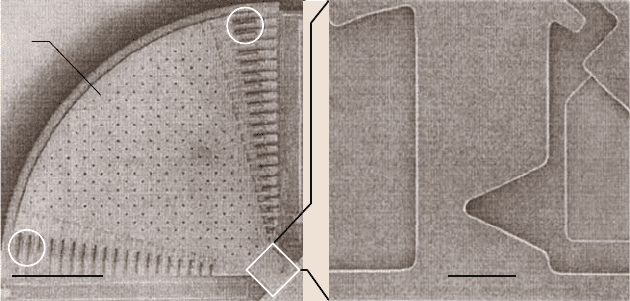
Another device that can be used to investigate fatigue resistance in MEMS
materials is shown in Fig. 23.14 [27]. In this case, a large mass is attached to the
end of a notched cantilever beam. The mass contains two comb drives on opposite
ends. When an AC signal is applied to one comb drive, the device will resonate,
cyclically loading the notch. The comb drive on the opposite side is used as a cap-
acitive displacement sensor. This device contains many fewer comb fingers than the
device shown in Fig. 23.13. As a result, it can apply cyclic loads by exploiting the
resonance frequency of the device, but it cannot supply sufficient force to achieve
monotonic loading.
Fatigueloadinghas also been studiedusing thesame externalloading techniques
shown in Fig. 23.7. In this case, the frequency of the cyclic load is considerably
100 μm 10 μm
a)
c)
b)
Fig. 23.14. SEM of a device used to investigate fatigue; the image on the right is a higher
magnification view of the notch near the base ofthe moving part of the structure [27]: a) mass,
b) comb drive actuator, c) capacitive displacement sensor
23 Mechanical Properties of Micromachined Structures 1313
lower, since the resonance frequency of the device is not being utilized. This leads
to longer high-cycle testing times. Since the force is essentially unlimited, however,
this technique allows a variety of frequencies to be studied to determine their effect
on the fatigue behavior.
Friction Measurements
Friction is another property that has been studied in micromachined structures. To
study friction, of course, two surfaces must be brought into contact with each other.
This is usually avoided at all costs for these devices because of the risk of stic-
tion. (Stiction is the term used when two surfaces that come into contact adhere so
strongly that they cannot be separated.) Even so, a few devices have been designed
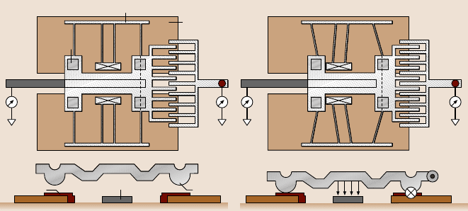
that can investigate friction. One of these is shown schematically in Fig. 23.15 [29].
It consists of a movable structure with a comb-drive on one end and a cantilever
beam on the other. Beneath the cantilever, on the substrate, is a planar electrode.
The device is moved to one side using the comb-drive. Then a voltage is applied
between the cantilever beam and the substrate electrode. The voltage on the comb-
drive is then released. The device would normally return to its original position, to
relax the deflection in the truss suspensions, but the friction between the cantilever
and the substrate electrode holds it in place. The voltage to the substrate electrode is
slowly decreased until the device starts to slide. Given the electrostatic force gener-
ated bythe substrate electrodeand the stiffness of the truss suspensions,it is possible
to determine the static friction. For this device,bumps were fabricated on the bottom
of each cantilever beam. This limited the surface area that came into contact with
the substrate and so lowered the risk of stiction.
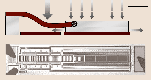
Anotherdevice designed to study friction is shown in Fig. 23.16 [30]. This tech-
nique uses a hinged cantilever. The portion near the free end acts as the friction
test structure, and the portion near the anchored end acts as the driver. The friction
Truss suspension
Position
marker
Dimple
Nitride
pad
V
c
=0 V
DC
=0
Nitride pad
Electrode Dimple
V
c
=V
clamp
F
friction
V
DC
= V
x
F
normal
F
suspension
F
friction
A–A B–B
Polysilicon
ground plane
a) b)
Fig. 23.15a,b. Schematics depicting a device used to study friction. (a) shows top and side
views of the device in its original position, and (b) shows views of the device after it has been
displaced using the comb-drive and clamped using the substrate electrode [29]
1314 Harold Kahn
200 μm
Slip
Fig. 23.16. Schematic cross-section and top-view optical micrograph of a hinged-cantilever
test structure for measuring friction in micromachined devices [30]
test structure is attracted to the substrate by means of electrostatic actuation, and
when a second electrostatic actuator pulls down the driver, the friction test structure
slips forwardby a length proportionalto the forces involved,including the frictional
force. This distance, however, has a maximum of 30nm, so all measurements must
be exceedingly accurate in order to investigate a range of forces. This test struc-
ture can be used to determine the friction coefficients for surfaces with and without
lubricating coatings.
23.3 Measurements of Mechanical Properties
All of the techniques discussed in Sects. 23.1 and 23.2 have been used to measure
the mechanical properties of MEMS and NEMS materials. As a general rule, the
results from the various techniques have agreed well with each other, and the ar-
gument becomes which of the measurement techniques is easiest and most reliable
to perform. It is crucial to bear in mind, however, that certain properties (such as
strength) are process-dependent, and so the results taken at one laboratory will not
necessarily match those taken from another. This will be discussed in more detail in
Sect. 23.3.1.
23.3.1 Mechanical Properties of Polysilicon
In current MEMS technology, the most widely used structural material is polysili-
con deposited by low-pressure chemical vapor deposition (LPCVD). One reason for
the prevalenceof polysilicon is the large body of processing knowledge for this ma-
terial that has been developed by the integrated circuit community. Another reason,
of course, is that polysilicon possesses a number of qualities that are beneficial to
MEMS devices, in particular high strength and Young’s modulus. Therefore, most
of the mechanical properties investigations performed on MEMS materials have fo-
cused on polysilicon.
