Bhushan B. Nanotribology and Nanomechanics: An Introduction
Подождите немного. Документ загружается.

21 Micro/Nanotribology and Micro/Nanomechanics of Magnetic Storage Devices 1163
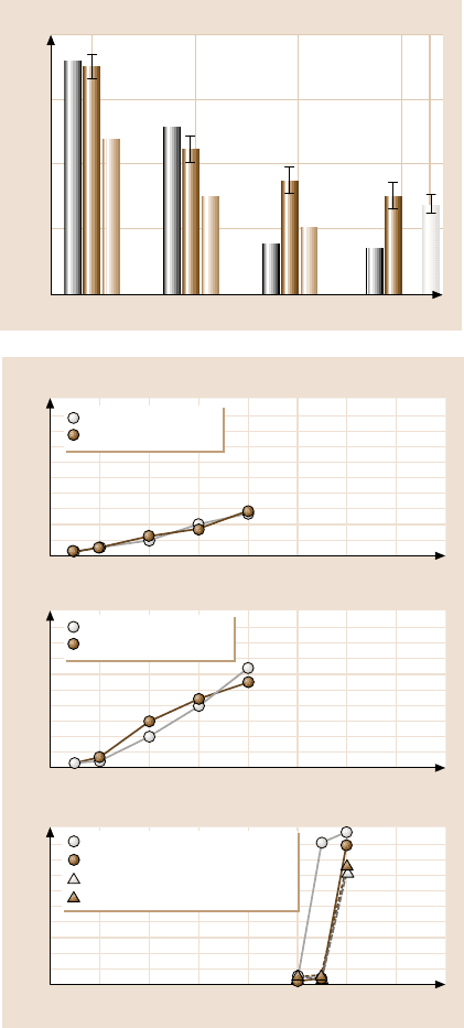
Critical load (μN)
100
75
50
25
0
20 nm 10 nm 5 nm 3.5 nm
Si(100)
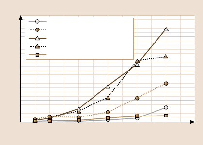
Fig. 21.23. Summary of criti-
cal loads estimated from the
coefficient of friction profiles
and AFM images [20]
500
400
300
200
100
0
020406080
500
400
300
200
100
0
020406080
500
400
300
200
100
0
020406080
MP, parallel
MP, perpendicular
Scratch depth (nm)
a)
Normal load (μN)
Scratch depth (nm)
b)
Normal load (μN)
Scratch depth (nm)
c)
Normal load (μN)
BaFe, parallel
BaFe, perpendicular
ME (H = 2.5 GPa), parallel
ME (H = 0.7), parallel
ME (H = 4.3), perpendicular
ME (H = 1.0), perpendicular
Fig. 21.24. Scratch depth as
a function of normal load
after one scratch cycle for
(a)MP,(b) BaFe, and (c)ME
tapes along parallel and per-
pendicular directions with
respect to the longitudinal
axis of the tape [47]
1164 Bharat Bhushan
500
250
0
5.00
(nm)
0
2.50
5.00
0
2.50
5
10
20
30
40
500
250
0
5.00
(nm)
0
2.50
5.00
0
2.50
5
10
20
30
40
1500
750
0
8.00
(nm)
0
4.00
8.00
0
4.00
50
60
65
2.00
6.00
6.00
2.00
55
1500
750
0
8.00
(nm)
0
4.00
8.00
0
4.00
50
60
2.00
6.00
6.00
2.00
55
c)
d)
a)
(μN)
(μm)
b)
(μm)
(μN)
(μm)
(μN)
(μm)
(μN)
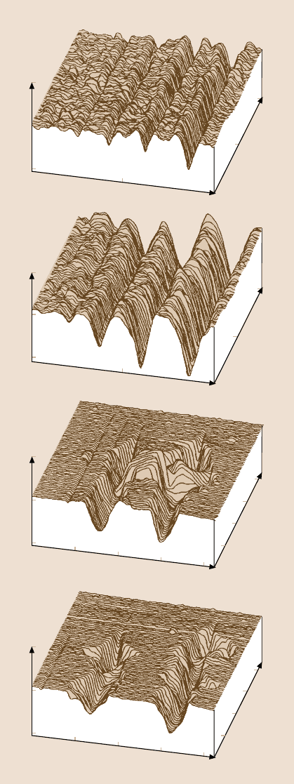
Fig. 21.25. Surface maps for
scratched (a)MP,(b) BaFe,
(c)ME(H= 0.7GPa),and
(d)ME(H= 2.5 GPa) tapes
along parallel direction. Nor-
mal loads used for scratching
for one cycle are listed in the
figure [47]
21 Micro/Nanotribology and Micro/Nanomechanics of Magnetic Storage Devices 1165
depends on the binder, pigment volume concentration (PVC) and the head clean-
ing agent (HCA) contents. ME tapes appear to be much more scratch resistant than
the particulate tapes. However, the ME tape breaks up catastrophically in a brittle
mode at a normal load higher than the 50µN (Fig. 21.25), as compared to parti-
culate tapes in which the scratch rate is constant. They reported that the hardness
of ME tapes is higher than that of particulate tapes, however, a significant differ-
ence in the nanoindentation hardness values of the ME film from region to region
(Table 21.3) was observed. They systematically measured scratch resistance in the
high and low hardness regions along and across the longitudinal directions. Along
the parallel direction, load required to crack the coating was lower (implying lower
scratch resistance) for a harder region, than that for a softer region. The scratch re-
sistance of high hardness region along the parallel direction is slightly poorer than
that for along perpendicular direction. Scratch widths in both low and high hardness
regions is about half (≈ 2µm) than that in perpendicular direction (≈ 1 µm). In the
parallel direction, the material is removed in the form of chips and lateral crack-
ing also emanates from the wear zone. ME films have columnar structure with the
columns lined up with an oblique angle of on the order of about 35
◦
with respect to
the normal to the coating surface [3,60]. The columnorientation may be responsible
for directionality effect on the scratch resistance. Hibst [60] havereported the direc-
tionality effect in the ME tape-head wear studies. They have found that the wear
rate is lower when the head moves in the direction corresponding to the column
orientation than in the opposite direction.
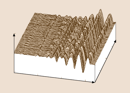
PET films could be scratched at loads of as low as about 2 µN (Fig. 21.26).
Figure 21.26a shows scratch marks made at various loads. Scratch depth along the
scratch does not appear to be uniform. This may occur because of variations in the
mechanical propertiesof the film. Bhushan and Koinkar [45] also conducted scratch
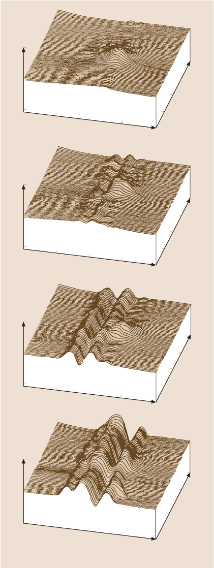
studies in the selected particulate regions. Scratch profiles at increasing loads in the
particulate region are shown in Fig. 21.26b. We note that the bump (particle) is
barely scratched at 5µN and it can be scratched readily at higher loads. At 20µN, it
essentially disappears.
500
250
0
(nm)
0
2.00
0
4.00
24
6
815
4.00
6.00
2.00
6.00
10 20
(μN)
(μm)
Fig. 21.26. Surface pro-
files for scratched PET film
(a) polymer region, (b) ce-
ramic particulate region.
The loads used for various
scratches at ten cycles are
indicated in the plots [45]
1166 Bharat Bhushan
500
250
0
(nm)
0
1.00
0
3.00
3.00
2.00
4.00
2.00
4.00
1.00
500
250
0
(nm)
0
1.00
0
3.00
3.00
2.00
4.00
2.00
4.00
1.00
500
250
0
(nm)
0
1.00
0
3.00
3.00
2.00
4.00
2.00
4.00
1.00
500
250
0
(nm)
0
1.00
0
3.00
3.00
2.00
4.00
2.00
4.00
1.00
(μm)
5 μN
10 cyc.
(μm)
10 μN
10 cyc.
(μm)
15 μN
10 cyc.
(μm)
20 μN
10 cyc.
Fig. 21.26. (continued)
21 Micro/Nanotribology and Micro/Nanomechanics of Magnetic Storage Devices 1167
21.5.3 Microscale Wear
By scanning the sample (in 2D) while scratching, wear scars are generated on the
sample surface [16,18,28,45–49,53,54,57,58].The major benefit of a single cycle
wear test over a scratch test is that wear data can be obtained over a large area.
Magnetic Head Materials
Figure 21.27 shows the wear depth as a function of load for one cycle for different
slider materials. Variation in the wear depth in the wear mark is dependent upon
the material. It is generally within ±5%. The mean wear depth increases with the
increase in normal load. The representative surface profilesshowing the wear marks
(central2 µm×2 µm region)at a normalloadof 60µN forall specimensare shownin
Fig. 21.28. The material is removed uniformly in the wear region for all specimens.
Table 21.2 presents average wear depth at 60µN normal load for all specimens.
Microwear resistance of SiC and Al
2
O
3
is the highest followed by Al
2
O
3
−
TiC,
single-crystal and polycrystalline Mn
−
Zn ferrite.
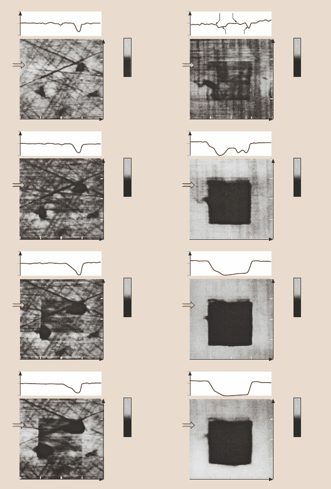
Next, wear experimentswere conducted for multiple cycles. Figure 21.29 shows
the 2-D gray scale plots and corresponding section plot (on tope of each gray scale
plot),taken at a locationshown by an arrowfor Al
2
O
3
(leftcolumn) and Al
2
O
3
−
TiC
(right column) specimen obtained at a normal load of 20µNandatadifferent num-
ber of scan cycles. The central regions (2µm × 2 µm) show the wear mark gen-
erated after a different number of cycles. Note the difference in the vertical scale
of gray scale and section plots. The Al
2
O
3
specimen shows that wear initiates at
the porous holes or defects present on the surface. Wear progresses at these loca-
tions as a function of number of cycles. In the porous hole free region, microwear
resistance is higher. In the case of the Al
2
O
3
−
TiC specimen for about five scan cy-
cles, the microwear resistance is higher at the TiC grains and is lower at the Al
2
O
3
grains. The TiC grains are removed from the wear mark after five scan cycles. This
indicates that microwear resistance of multi-phase materials depends upon the in-
dividual grain properties. Evolution of wear is uniform within the wear mark for
250
200
150
100
50
0
Normal load (μN)
0 20 40 60 80 100 120
Wear depth (nm)
Al
2
O
3
Al
2
O
3
–TiC
Mn–Zn ferrite
Single-crystal Mn–Zn ferrite
SiC
Fig. 21.27. Wear depth as
a function of normal load after
one scan cycle for Al
2
O
3
,
Al
2
O
3
−
TiC, polycrystalline
Mn
−
Zn ferrite, single-crystal
Mn
−
Zn ferrite and SiC [28]
1168 Bharat Bhushan
1.0
200
100
0
(nm)
0
2.0
3.0
4.0
0
1.0
2.0
3.0
4.0
1.0
200
100
0
(nm)
0
2.0
3.0
4.0
0
1.0
2.0
3.0
4.0
1.0
400
200
0
(nm)
0
2.0
3.0
4.0
0
1.0
2.0
3.0
4.0
1.0
400
200
0
(nm)
0
2.0
3.0
4.0
0
1.0
2.0
3.0
4.0
1.0
200
100
0
(nm)
0
2.0
3.0
4.0
0
1.0
2.0
3.0
4.0
W = 60 μN
d = 3.7 nm
1 cycle
μm
Al
2
O
3
W = 60 μN
d = 22.0 nm
1 cycle
μm
Al
2
O
3
–TiC
W = 60 μN
d = 83.6 nm
1 cycle
μm
Poly Mn– Zn Ferrite
W = 60 μN
d = 56.0 nm
1 cycle
μm
SC Mn– Zn Ferrite
W = 60 μN
d = 7.7 nm
1 cycle
μm
SiC
Fig. 21.28. Surface profiles
showing the worn region
(center 2 µm ×2 µm) after
one scan cycles at a normal
load of 60 µNforAl
2
O
3
,
Al
2
O
3
−
TiC, polycrystalline
Mn
−
Zn ferrite, single-crystal
Mn
−
Zn ferrite and SiC [28]
21 Micro/Nanotribology and Micro/Nanomechanics of Magnetic Storage Devices 1169
4.00
3.00
2.00
1.00
0
0 1.00 2.00
3.00
4.00
25
0
–25
4.00
3.00
2.00
1.00
0
0 1.00 2.00
3.00
4.00
100.0
50.0
0.0
(nm)
75
0
–75
4.00
3.00
2.00
1.00
0
0 1.00 2.00
3.00
4.00
150.0
75.0
0.0
(nm)
50
0
–50
4.00
3.00
2.00
1.00
0
0 1.00 2.00
3.00
4.00
200.0
100.0
0.0
(nm)
150
0
–150
4.00
3.00
2.00
1.00
0
0 1.00 2.00
3.00
4.00
100.0
50.0
0.0
(nm)
100
0
–100
4.00
3.00
2.00
1.00
0
0 1.00 2.00
3.00
4.00
100.0
50.0
0.0
(nm)
150
0
–150
4.00
3.00
2.00
1.00
0
0 1.00 2.00
3.00
4.00
400.0
200.0
0.0
(nm)
50
0
–50
4.00
3.00
2.00
1.00
0
0 1.00 2.00
3.00
4.00
100.0
50.0
0.0
(nm)
50
0
–50
(nm)
(nm)
(nm)
(nm)
(nm)
(nm)
(nm)
(nm)
100.0
50.0
0.0
(nm)
Al
2
O
3
W = 20 μ
(μm)
(μm)
(μm)
(μm)
(μm)
(μm)
(μm)
(μm)
N
d = 3.0 nm
1 cycle
Al
2
O
3
–TiC
W = 20 μN
d = 6.5 nm
1 cycle
W = 20 μN
d = 8.6 nm
5 cycles
W = 20 μN
d = 40.0 nm
5 cycles
W= 20 μN
d = 16.6 nm
15 cycles
W =20μN
d =140 nm
15 cycles
W = 20 μN
d = 20.2 nm
25 cycles
W= 20 μN
d = 186 nm
25 cycles
TiC
Al
2
O
3
Fig. 21.29. Gray scale 2-D plots showing the worn region (center 2 µm×2 µm) at a normal
load of 20 µN and different number of scan cycles for Al
2
O
3
and Al
2
O
3
−
TiC. The 2-D sec-
tion plots taken at a location shown by an arrow are shown on the top of corresponding gray
scale plot. Note the change in vertical scale for gray scale and 2-D section plots [28]
1170 Bharat Bhushan
400
350
300
250
200
150
100
50
0
Number of cycles
0 102030405060
Wear depth (nm)
Al
2
O
3
Al
2
O
3
–TiC
Poly Mn–Zn ferrite
Single-crystal
Mn–Zn ferrite
SiC
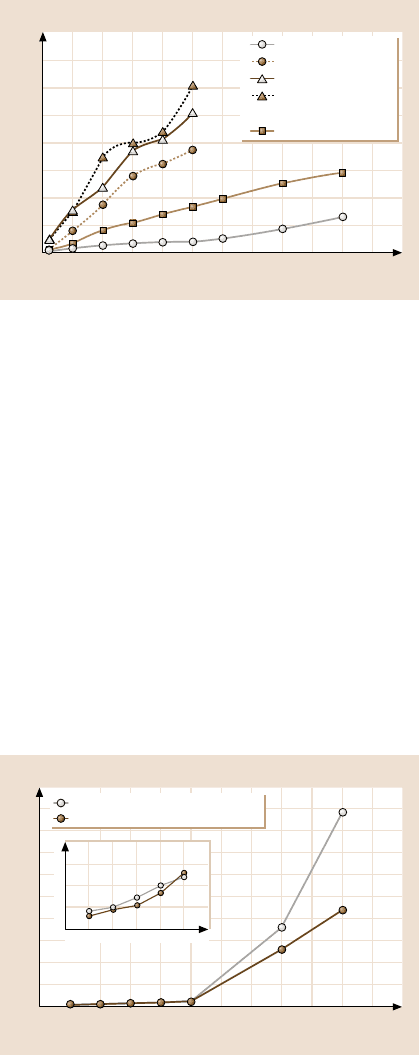
Fig. 21.30. Wear depth as
a function of number of cy-
cles at a normal load of 20 µN
for Al
2
O
3
,Al
2
O
3
−
TiC, poly-
crystalline Mn
−
Zn ferrite,
single-crystal (SC) Mn
−
Zn
ferrite and SiC [28]
ferrite specimens. Figure 21.30 shows plot of wear depth as a function of num-
ber of cycles at a normal load of 20 µN for all specimens. The Al
2
O
3
specimen
reveals highest microwear resistance followed by SiC, Al
2
O
3
−
TiC, polycrystalline
and single-crystal Mn
−
Zn ferrite. Wear resistance of Al
2
O
3
−
TiC is inferior to that
of Al
2
O
3
. Chu et al. [61] studied friction and wear behavior of the single-phase
and multi-phase ceramic materials and found that wear resistance of multi-phase
materials was poorer than single-phase materials. Multi-phase materials have more
material flaws than the single-phase material. The differences in thermal and mech-
anical properties between the two phases may lead to cracking during processing,
machining or use.
Magnetic Media
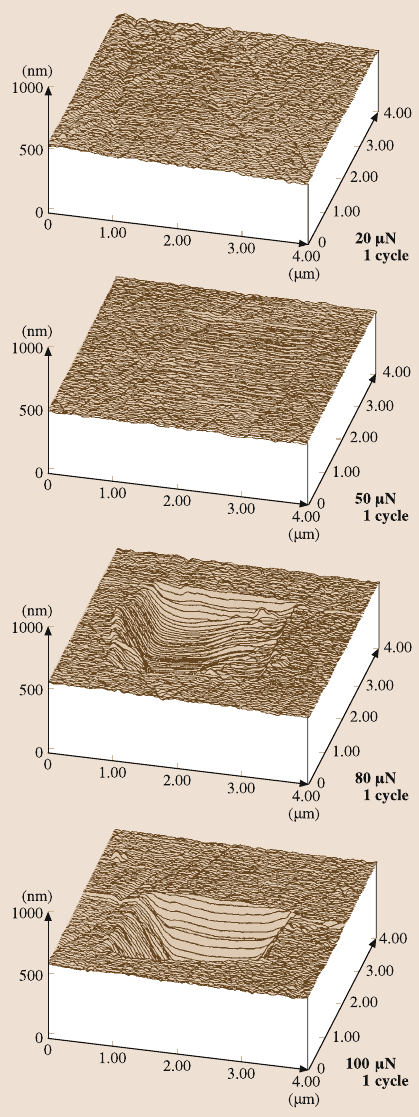
Figure 21.31 shows the wear depth as a function of load for one cycle for the pol-
ished, unlubricated and lubricated disks [18]. Figure 21.32 shows profiles of the
wear scars generated on unlubricated disk. The normal force for the imaging was
500
400
300
200
100
0
Wear depth (nm)
0 20406080100120
Normal load (μN)
Unlubricated as-polished disk
Lubricated as-polished disk
20
15
10
5
0
0 102030405060
Fig. 21.31. Wear depth as
a function of normal load
for polished, lubricated and
unlubricated thin-film rigid
disks after one cycle [18]
21 Micro/Nanotribology and Micro/Nanomechanics of Magnetic Storage Devices 1171
Fig. 21.32. Surface maps of
a polished, unlubricated thin-
film rigid disk showing the
worn region (center 2µm×
2 µm) after one cycle. The
normal loads are indicted in
the figure [18]
1172 Bharat Bhushan
about 0.5µN and the loads used for the wear were 20, 50, 80 and 100µN as indi-
cated in the figure. We note that wear takes place relatively uniformly across the
disk surface and essentially independentof the lubrication for the disks studied. For
both lubricated and unlubricateddisks, the wear depth increases slowly with load at
low loads with almost the same wear rate. As the load is increased to about 60µN,
wear increases rapidly with load. The wear depth at 50 µN is about 14 nm, slightly
less than the thickness of the carbon film. The rapid increase of wear with load at
loads larger than 60 µN is an indication of the breakdown of the carbon coating on
the disk surface.
Figure 21.33 shows the wear depth as a function of number of cycles for the
polished disks (lubricated and unlubricated). Again, for both unlubricated and lu-
bricated disks, wear initially takes place slowly with a sudden increase between 40
and 50 cycles at 10µN. The sudden increase occurred after 10 cycles at 20µN. This
rapid increase is associated with the breakdown of the carbon coating. The wear
profiles at various cycles are shown in Fig. 21.34 for a polished, unlubricated disk
at a normal load of 20µN. Wear is not uniform and the wear is largely initiated at
the texture grooves present on the disk surface. This indicates that surface defects
strongly affect the wear rate.
Hard amorphous carbon coatings are used to provide wear and corrosion resis-
tance to magnetic disks and MR/GMR magnetic heads. A thick coating is desirable
for long durability; however, to achieve ever increasing high recording densities, it
is necessary to use as thin a coating as possible. Microwear data on various amor-
phous carbon coatings of different thicknesses have been conducted by Bhushan
and Koinkar [48], Koinkar and Bhushan [49], and Sundararajanand Bhushan [53].
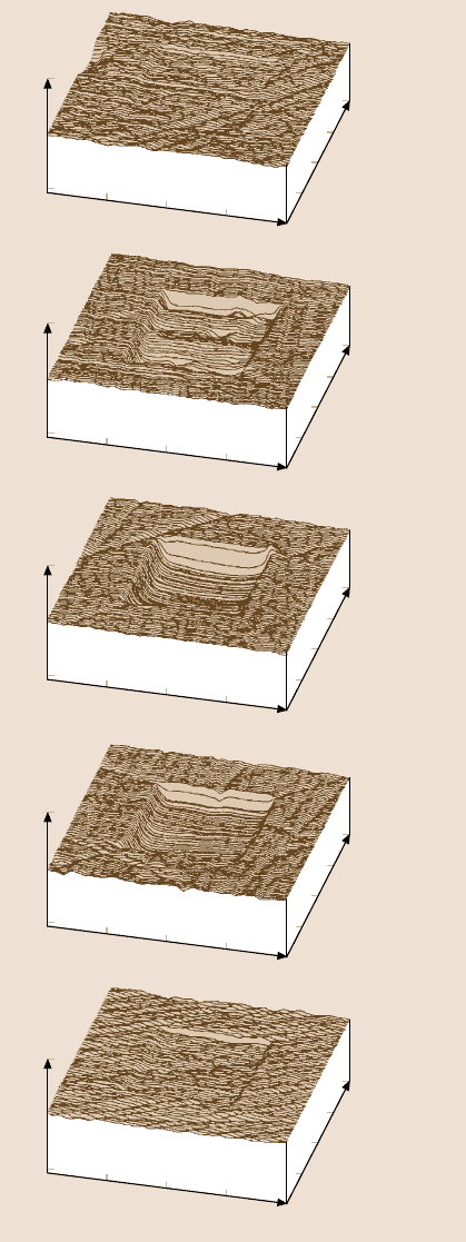
Figure 21.35 shows a wear mark on an uncoated Si(100) and various 10nm thick
carbon coatings. It is seen that Si(100) wears uniformly, whereas carbon coatings
wear nonuniformly. Carbon coating failure is sudden and accompanied by a sud-
den rise in friction force. Figure 21.36 shows the wear depth of Si(100) substrate
and various coatings at two different loads. FCA and ECR-CVD, 20nm thick coat-
ings show excellent wear resistance up to 80µN, the load that is required for the IB
20nm coating to fail. In these tests, failure of a coating results when the wear depth
exceeds the quoted coating thickness. The SP 20nm coating fails at the much lower
load of 35µN. At 60 µN, the coating hardly provides any protection. Moving on
to the 10nm coatings, ECR-CVD coating requires about 40 cycles at 60µNtofail
as compared to IB and FCA, which fail at 45µN. the FCA coating exhibits slight
roughening in the wear track after the first few cycles, which leads to an increase
in the friction force. The SP coating continues to exhibit poor resistance, failing
at 20µN. For the 5 nm coatings, the load required to fail the coatings continues to
decrease. But IB and ECR-CVD still provide adequate protection as compared to
bare Si(100) in that order, failing at 35 µN compared to FCA at 25µNandSPat
20µN. Almost all the 20, 10, and 5 nm coatings provide better wear resistance than
bare silicon. At 3.5
nm, FCA coating provides no wear resistance, failing almost in-
stantly at 20 µN. The IB and ECR-CVD coating show good wear resistance at 20 µN
