Bhadeshia H.K.D.H., Honeycombe R. Steels: Microstructure and Properties
Подождите немного. Документ загружается.

198 CHAPTER 9 THE TEMPERING OF MARTENSITE
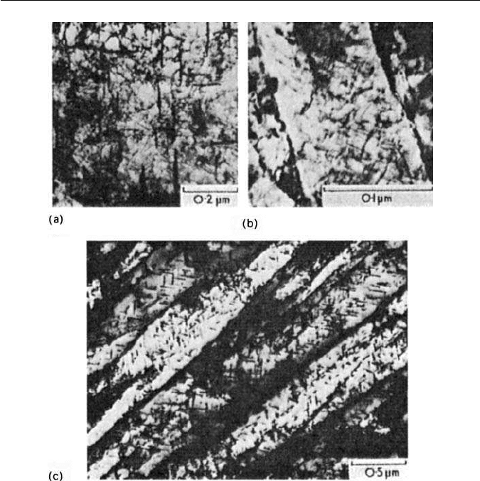
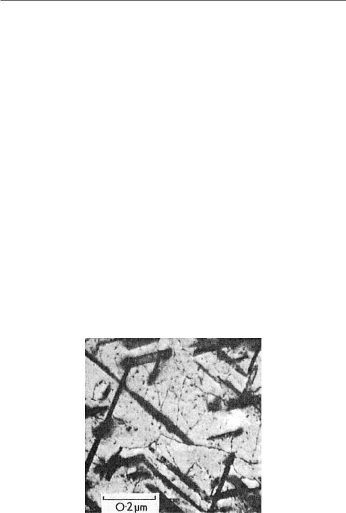
Fig. 9.11 Tempering of an Fe–4Mo–0.2C steel. Thin-foil electron micrographs: (a) 4.5 h at
550
◦
C. Cementite transforming in situ to Mo
2
C and start of nucleation on dislocations (Raynor
et al., 1966). (b) 5 h at 600
◦
C. Mo
2
C precipitation on dislocations within a former martensite
lath (courtesy of Irani). (c) 30 min at 700
◦
C. Mo
2
C precipitation in ferrite laths inherited from
martensite M
6
C precipitation at lath boundaries (Irani).
identified by dark field microscopy. On further tempering, the positions of the
original cementite particles are indicated by small necklaces of alloy carbides
which tend to be coarser than the matrix precipitation.
Figure 9.11a also illustrates the dislocation network characteristic of tem-
pered steels and inherited from the martensite, although there has been
considerable rearrangement and reduction in dislocation density. Dark field
electron microscopy reveals that these dislocations are the sites for very fine
precipitation of the appropriate alloy carbide. On further ageing the par-
ticles are more readily resolved, e.g. in Mo steels as a Widmanstätten array,

9.4 TEMPERING OF ALLOY STEELS 199
comprising Mo
2
C rodlets lying along 001
α
directions. Figure 9.11b illustrates
this stage in a single martensitic lath. Heavier precipitation is evident at the lath
boundaries.
The nucleation of carbides at the various types of boundary is to be expected
because these are energetically favourable sites which also provide paths for rel-
atively rapid diffusion of solute. Consequently theageing processis usuallymore
advanced in these regions and the precipitate is more massive (Fig. 9.11c). In
many alloy steels, the first alloy carbide to form is not the final equilibrium car-
bide and,in some steels, as many as three alloy carbides can form successively. In
these circumstances, the equilibrium alloy carbide frequently nucleates first in
the grain boundaries, grows rapidly and eventually completely replaces theWid-
manstätten non-equilibrium carbide within the grains. This is illustrated in Fig.
9.11c for a 4 wt% Mo steel tempered 30 min at 700
◦
C, in which M
6
C equi-axed
particles are growing at the grain boundaries but Widmanstätten Mo
2
C is still
visible within the grains. It is interesting to note that the structure still possesses
the lath-shaped ferrite grains inherited from the martensite. Recrystallization
occurs after longer times at 700
◦
C.
9.4.4 Tempering of steels containing vanadium
Vanadium is a strong carbide former and, in steel with as little as 0.1 wt% V, the
face-centred cubic vanadium carbide (VC) is formed. It is often not of stoichio-
metric composition, being frequently nearer V
4
C
3
, but with other elements in
solid solution within the carbide. Normally, this is the only vanadium carbide
formed in steels, so the structural changes during tempering of vanadium steels
are relatively simple.
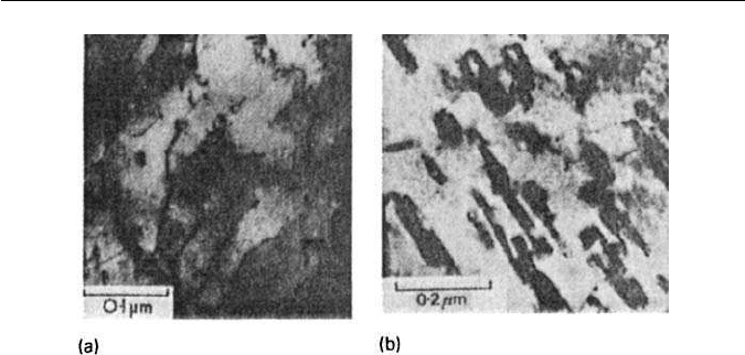
Vanadium carbide forms as small platelets, initially less than 5 nm across and
not more than 1 nm thick. These form within the ferrite grains on dislocations
(Fig. 9.12a) in the range 550–650
◦
C,and produce a marked secondary-hardening
peak. There is a well-defined orientation relationship (Baker/Nutting) with the
ferrite matrix: {100}
VC
//{110}
α
. In the early stages of precipitation at 550
◦
C,
the particles are coherent with the matrix, there being only a 3% misfit between
010
α
and 110
VC
. However,at 700
◦
C,the platelets coarsen rapidly (Fig. 9.12b)
and begin to spheroidize. However, the original martensite laths can still be
recognized, and are only replaced by equi-axed ferrite grains after long periods
at 700
◦
C.
Many steels containing vanadium, e.g. ½Cr½Mo¼V, 1Cr¼V, 3Cr1Mo¼V,
1Cr1Mo¾V,will exhibit extensive vanadiumcarbide precipitation on tempering,
because of the stability of this carbide, not only with respect to cementite but
also the several chromium carbides and molybdenum carbide (see Fig. 4.5).
Because of its ability to maintain a fine carbide dispersion, even at temperatures
approaching 700
◦
C,vanadium is an important constituent of steels for elevated
temperature service.
200 CHAPTER 9 THE TEMPERING OF MARTENSITE
Fig. 9.12 Fe–1V–0.2C wt% quenched and tempered. Thin-foil electron micrographs: (a) 72 h
at 550
◦
C,VC nucleation on dislocations (courtesy of Raynor); (b) 50 h at 700
◦
C. Plates of VC
(courtesy of Irani).
9.4.5 Tempering of steels containing chromium
In chromium steels, two chromium carbides are very often encountered: Cr
7
C
6
(trigonal) and Cr
23
C
6
(complex cubic). The normal carbide sequence during
tempering is:
Matrix → (FeCr)
3
C → Cr
7
C
3
→ Cr
23
C
6
.
While this sequence occurs in higher-chromium steels, below about 7 wt%
Cr, Cr
23
C
6
is absent unless other metals such as molybdenum are present.
Chromium is a weaker carbide former than vanadium, which is illustrated by
the fact that Cr
7
C
3
does not normally occur until the chromium content of the
steel exceeds 1 wt% at a carbon level of about 0.2 wt%.
In steels up to 4 wt% Cr, the transformation from Fe
3
CtoCr
7
C
3
occurs
mainly by nucleation at the Fe
3
C/ferrite interfaces. Steels up to 9 wt% Cr do
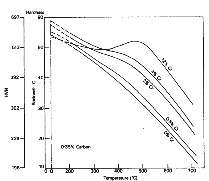
not show secondary-hardening peaks in tempering curves (Fig. 9.13). However,
these curves do exhibit plateaus at the higher chromium contents, which are
associated with the precipitation of Cr
7
C
3
. Chromium diffuses more rapidly
in ferrite than most metallic alloying elements, with the result that Cr
7
C
3
is
detected during tempering at temperatures as low as 500
◦
C, and in compari-
son with vanadium carbide,chromium carbide coarsens rapidly. Thus, in a 2 wt%
Cr–0.2 wt% C steel, continuous softening will normally occur on tempering
between 500
◦
C and 700
◦
C, although addition of other alloying elements, e.g.
Mo, can reduce the rate of coarsening of Cr
7
C
3
.
In contrast, a 12 wt% Cr steel will exhibit secondary hardening in the
same temperature range (Fig. 9.13) due to precipitation of Cr
7
C
3
. Addition-
ally, Cr
23
C
6
nucleates at about the same time but at different sites, particularly
former austenite grain boundaries and at ferrite lath boundaries. This precipi-
tate grows at the expense of the Cr
7
C
3
which eventually disappears from the
9.4 TEMPERING OF ALLOY STEELS 201
Fig. 9.13 The effect of chromium on the tempering of a 0.35 wt% C steel (Bain and Paxton,
The Alloying Elements in Steel, 2nd edition, ASM, Ohio, USA, 1961).
microstructure, at which stage the steel has completely over-aged. This transi-
tion from Cr
7
C
3
to Cr
23
C
6
in high-chromium steels is by separate nucleation and
growth. Further alloying additions can promote one or other of these carbide
reactions, e.g. addition of tungsten encourages formation of Cr
23
C
6
by allowing
it to nucleate faster, while vanadium tends to stabilize Cr
7
C
3
. In doing so, it
decreases the rate of release into solution of chromium and carbon needed for
the growth of Cr
23
C
6
. Clearly, vanadium would be a preferred addition to tung-
sten, if a fine stable chromium carbide dispersion is needed in the temperature
range 550–650
◦
C.
9.4.6 Tempering of steels containing molybdenum and tungsten
When molybdenum or tungsten is the predominant alloying element in a steel,
a number of different carbide phases are possible, but for composition between
4 and 6 wt% of the element the carbide sequence is likely to be:
Fe
3
C → M
2
C → M
6
C.
202 CHAPTER 9 THE TEMPERING OF MARTENSITE
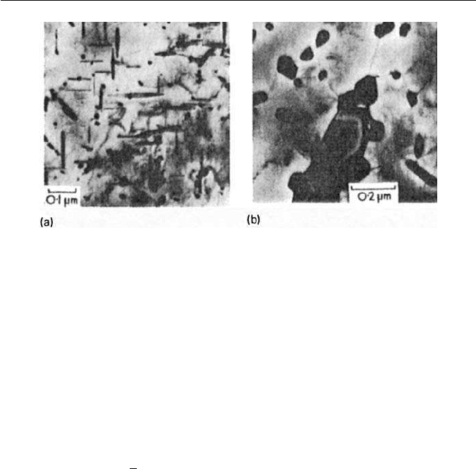
Fig. 9.14 Fe–6W–0.23C wt% quenched and tempered (courtesy of Davenport).Thin-foil elec-
tron micrographs: (a) 100 h at 600
◦
C. W
2
C needles along 001
α
some irregular particles of
M
6
C. (b) 26 h at 700
◦
C. Massive M
6
C.
The carbides responsible for the secondary hardening in both the case of tung-
sten and molybdenum are the isomorphous hexagonal carbides Mo
2
C andW
2
C,
both of which, in contrast to vanadium carbide, have a well-defined rodlet
morphology (Fig. 9.14a). When formed inthe matrix,M
2
C adopts aWidmanstät-
ten distribution lying along 100
α
directions. In molybdenum steels, peak
hardness occurs after about 25 h at 550
◦
C, when the rods are about 10–20 nm
long and 1–2 nm in diameter. The orientation relationship is:
(0001)
M
2
C
//(011)
α
,
[11
20]
M
2
C
//[100]
α
(rod growth direction).
M
2
C also nucleates at former austenite and ferrite lath boundaries. As in the
case of vanadium steels, M
2
C precipitate nucleates both on dislocations in the
ferrite, and at the Fe
3
C/ferrite interfaces, but the secondary hardening arises
primarily from the dislocation-nucleated dispersion of M
2
C.
On prolonged tempering at 700
◦
C, the complex cubic M
6
C forms predom-
inantly at grain boundaries as massive particles which grow quickly, while the
M
2
C phase goes back into solution.The equilibrium microstructure is equi-axed
ferrite with coarse M
6
C in the form of faceted particles at grain boundaries, and
plates, illustrated in Fig. 9.14b for a 6 wt% tungsten steel tempered 26 h at 700
◦
C.
For similar atomic concentrations, the secondary hardening response in the
case of tungsten steels is less than that of molybdenum steels. The M
2
C disper-
sion in the former case is coarser, probably because the slower diffusivity of
tungsten allows a coarsening of the dislocation network prior to being pinned
by the nucleation of M
2
C particles.
At lowerconcentration of tungsten and molybdenum (0.5–2 wt%), two other
alloy carbides are interposed in the precipitation sequences, i.e. the complex
9.4 TEMPERING OF ALLOY STEELS 203
cubic M
23
C
6
and the orthorhombic M
a
C
b
, probably Fe
2
MoC. These carbides
are found as intermediate precipitates between M
2
C and M
6
C.
9.4.7 Complex alloy steels
The presence of more than one carbide-forming element can complicate the
precipitation processes during tempering. In general terms, the carbide phase
which is the most stable thermodynamically will predominate, but this assumes
that equilibrium is reached during tempering. This is clearly not so at tempera-
tures below 500–600
◦
C.The use of pseudo-binary diagrams for groups of steels,
e.g. Cr–V, Cr–Mo, can be a useful guide to carbide phases likely to form dur-
ing tempering (see Chapter 4, Section 4.2). The sequence of precipitation for
a particular composition can be approximated to by drawing a line from the
origin of the diagram, e.g. Fig. 4.6, to the composition of interest. The phase
fields passed through would normally be those encountered in tempering, but
the exact conditions cannot be forecast from such data.
Certain strong carbide formers, notably niobium, titanium and vanadium,
haveeffects on temperingout ofproportionto their concentration. Inconcentra-
tions of 0.1 wt% or less, provided the tempering temperature is high enough, i.e.
550–650
◦
C,they combine preferentially with part of the carbon and, in addition
to the major carbide phase, e.g. Cr
7
C
3
,Mo
2
C, they form a separate, very much
finer dispersion, more resistant to over-ageing (Fig. 9.15). This secondary dis-
persion can greatly augment the secondary-hardening reaction, illustrating the
importance of these strong carbide-forming elements in achieving high strength
levels, not only at room temperature but also at elevated temperatures, where
creep resistance is often an essential requirement.
Fig. 9.15 Fe–4Mo–0.1Nb–0.2C wt% steel tempered 6 h at 700
◦
C. Coarse needles of Mo
2
C
in ferrite and fine particles of NbC on dislocations (courtesy of Irani). Thin-foil electron
micrograph.
204 CHAPTER 9 THE TEMPERING OF MARTENSITE
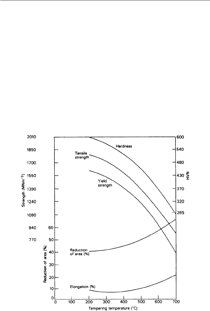
9.4.8 Mechanical properties of tempered alloy steels
A wide range of mechanical properties is obtainable by tempering alloy steels
between 200
◦
C and 700
◦
C. A typical example is shown in Fig. 9.16 for a steel
containing 1.5Ni–1Cr–0.25Mo–0.4C wt% (En24), the tensile strength of which
can be varied from 1800 down to 900 MN m
−2
by tempering at progressively
high temperatures. The ductility of the steel improves as the tensile strength
falls. However, there is a ductility minimum around 275–300
◦
C, which is often
observed in plain carbon and lower-alloy steels. This has been attributed to
the conversion of retained austenite to bainite, but it is more likely to be the
result of the formation of thin cementite films, as a result of the transformation
of austenite at the interlath boundaries. At higher temperatures, these films
spheroidize and the toughness improves.
To obtain really high strength levels in tempered steels (∼1500 MN m
−2
),it is
usual to temper at low temperatures, i.e. 200–300
◦
C,when the martensite is still
heavily dislocated and the main strengthening dispersion is cementite or ε-iron
Fig. 9.16 Mechanical properties of En 24 (1.5Ni–1Cr–0.25Mo–0.4C wt% steel) as a result of
tempering for 1 h (Thelning, Steel and its Heat Treatment, Bofors Handbook, Butterworth, UK,
1975).

9.4 TEMPERING OF ALLOY STEELS 205
Fig. 9.17 Comparison of mechanical properties of plain carbon and alloy steels tempered at
200
◦
C (Irving and Pickering, Journal of the Iron and Steel Institute 194, 137, 1960): (a) effect of C
on tensile strength; (b) relation between tensile strength and impact value. Note the beneficial
effect of Mo.
carbide. Alloy steels, when tempered in this range, not only provide very high
tensile strengths with some ductility but are also superior to plain carbon steels,
as shown in Fig. 9.17. It is clear from Fig. 9.17a that the carbon content has a large
influence on the strength. The alloying elements refine the iron carbide disper-
sion and, as the carbon contentis raised,the dispersionbecomes moredense and,
therefore, more effective. The toughness decreases with increasing strength, as
206 CHAPTER 9 THE TEMPERING OF MARTENSITE
shown in Fig. 9.17b. However, alloying elements very substantially improve the
toughness, when compared with plain carbon steels of similar strength levels.
When molybdenum is present in the steel, the toughness is increased further as
the scatter bands indicate. This effect of alloying elements is again attributed to
the breakdown of carbide films at grain and martensite lath boundaries. These
films are particularly less noticeable in steels containing molybdenum.
Alloy steels which exhibit secondary hardening can provide high strength
levels on tempering between 500
◦
C and 700
◦
C, with better ductility than that
obtained at lower tempering temperatures. However, one of their main advan-
tages is that, once a high strength level is reached by means of an alloy carbide
dispersion formed between 550
◦
C and 650
◦
C, this structure will be relatively
stable at temperatures up to 500
◦
C. Therefore, the steels are suitable for use
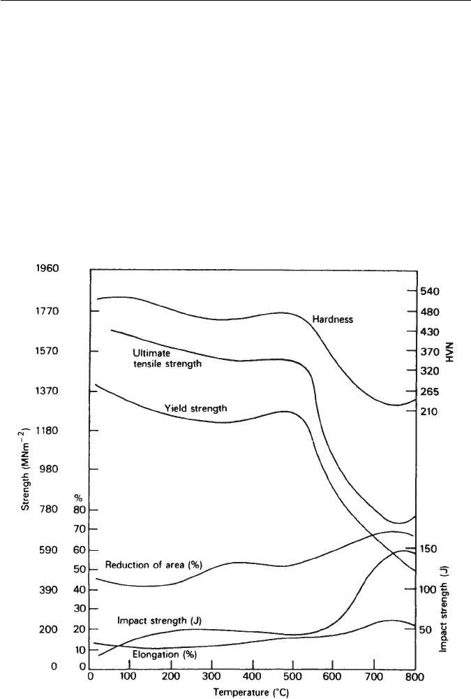
under stress at elevated temperatures. A typical example is given in Fig. 9.18 of
Fig. 9.18 Effect of tempering for 1 h on the mechanical properties of a 12Cr–1Ni–0.2C wt%
stainless steel. Typical results for 50-mm diameter bars, oil-quenched (Thelning, Steel and its
Heat Treatment, Bofors Handbook, Butterworth, 1975).

FURTHER READING 207
a 12Cr–1Ni–0.2C wt% stainless steel, which can be quenched to martensite and
then tempered to give a fine dispersion of chromium carbides in a ferritic matrix.
The strength is well-maintained up to the secondary-hardening peak at 500
◦
C,
and is combinedwith areasonable level ofductility. Thistype ofsteel istempered
to between 700 and 1000 MN m
−2
yield stress and is frequently used in steam
and gas turbines, but can also be used for constructional purposes where lower
temperatures are involved. Further improvements in mechanical properties at
elevated temperatures can be obtained by addition of small concentrations of
stronger carbide formers, e.g. molybdenum (2 wt%) and vanadium (0.25 wt%).
9.5 MARAGING STEELS
It has been shown that precipitation of alloy carbides in tempered martensite
gives rise to age hardening, usually referred to as secondary hardening. There is
no reason why other finely divided phases cannot be used for a similar purpose
and, in fact, an important group of high-alloy steels, the maraging steels, reach
high strength levels by the precipitation of various intermetallic compounds.
Carbide precipitation is practically eliminated by the use of low carbon
compositions, and the steels contain between 18 and 25 wt% nickel so that,
on quenching from the austenitic condition, they form a soft but heavily dis-
located martensite. The high nickel content lowers the M
s
to around 150
◦
C,but
on reheating the martensite there is considerable hysteresis, so that austenite
is not reformed until the steel is held between 500
◦
C and 600
◦
C. At somewhat
lower temperatures, i.e. 400–500
◦
C, precipitation of intermetallic phases takes
place, accelerated by the influence of the high dislocation density on the diffu-
sion of substitutional solute atoms. Elements such as molybdenum and titanium
are necessary additions, which result in the precipitation of Ni
3
Mo, Ni
3
Ti and
the Laves phase,Fe
2
Mo. Cobalt is also a useful alloying element as it reduces the
solubility of molybdenum in the matrix and this increases the volume fraction
of molybdenum-rich precipitate.
The precipitate reactions can lead to very high-volume fractions of precipi-
tate, and thus to the achievement of high strength levels (Equations (2.10) and
(2.11)). For example, a steel with 18–19 Ni, 8.5–9.5 Co, 4.5–5 Mo and 0.5–0.8
Ti wt% can be heat treated to give a yield stress around 2000 MN m
−2
. However,
the important point is that these high strength levels are accompanied by good
ductility and toughness.
FURTHER READING
Bhadeshia, H. K. D. H., Strang, A. and Gooch, D. J., Remanent life assessment and the
approach to equilibrium, International Materials Reviews 43, 45, 1998.
Brooks, C. R., Heat Treatment of Ferrous Alloys, McGraw-Hill, USA, 1979.
Honeycombe, R. W. K., Structure and Strength of Alloy Steels, Climax Molybdenum Co.,
Michigan, USA, 1973.