Becker W. Advanced Time-Correlated Single Photon Counting Techniques
Подождите немного. Документ загружается.

34 3 Multidimensional TCSPC Techniques
in the optical system. Consequently, the photons of the different signals are routed
into separate photon distributions.
In most applications multiplexing has advantages compared with consecutive re-
cording of the same signals. One advantage is that sequential recording by the se-
quencer can still be used at a time scale longer than the multiplexing period. In addi-
tion, slow changes in the sample have the same effect on all multiplexed signals.
Multiplexing has some similarities to multidetector operation. However, multi-
plexing is controlled by a determinate signal from some kind of experimental
control device. Moreover, multiplexing usually switches between the signals at a
rate much lower than the pulse repetition rate. Consequently, the photons of one
signal are recorded for a large number of signal periods before the system
switches to the next signal. Multidetector operation, on the other hand, is random.
The destination of a photon in the memory is controlled by a property of the pho-
ton itself, e.g. its wavelength, angle of polarisation, or location of emission. There-
fore multiplexing can be combined with multidetector operation. In this case a
number of channel bits are used for the detector channel information delivered by
the router. Other channel bits are used for multiplexing. Figure 3.6 illustrates the
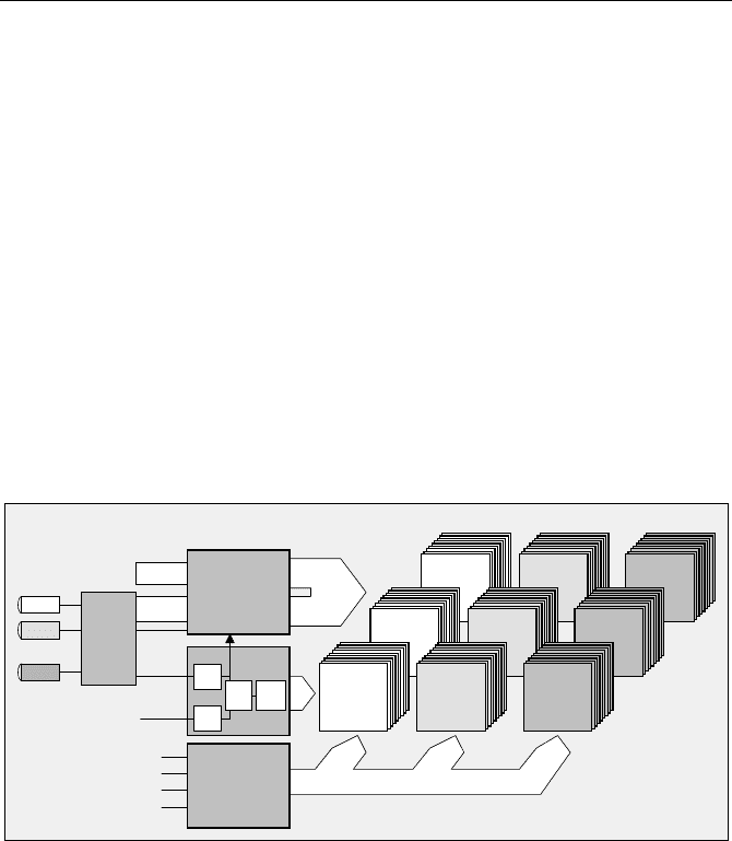
structure of a multiplexed multidetector system.
Photon
distribution
detector 1
Photon
distribution
detector 2
Photon
distribution
detector n
Mplx. ch. n Mplx. ch. n Mplx. ch. n
Photon
distribution
detector 1
Photon
distribution
detector 2
Photon
distribution
detector n
Mplx. ch. 2 Mplx. ch. 2 Mplx. ch. 2
measure-
Start
Stop
CFD
CFD
from laser
Time
t
Channel register
Experiment
Scan Clocks
etc.
Trigger
Reference
Sequencer
latch
ment
ADC
TAC
Channel
channel
PMT 1
.
.
.
.
.
PMT 2
PMT n
Router
Photon
distribution
detector 1
Photon
distribution
detector 2
Photon
distribution
detector n
T, X, Y, etc.
Dis.Cnt
Multiplexing
control
Detector
Mpx.
channel
Mplx. ch. 1 Mplx. ch. 1 Mplx. ch. 1
Channel
Fig. 3.6 Multiplexed multidetector system. The result can be considered a number of photon
distributions for all combinations of detector and multiplexing channels. Each photon distri-
bution is the photon density over the time in the signal period and the sequencer coordinates
The system records the photon distribution over the time in the signal period,
the detector channel number, the multiplex-channel number, and one or two addi-
tional coordinates determined by the sequencer. The result can be interpreted as a
sequence of photon distributions for all combinations of detector and multiplexing
channels.
An important application of multiplexed multidetector systems is diffuse opti-
cal tomography (DOT). In DOT several picosecond diode lasers are multiplexed
into the input of a fibre switch. The multiplexed lasers are switched consecutively
into a large number of optical fibres which deliver the light to the sample. The
3.3 Sequential Recording Techniques 35
diffusely transmitted light is recorded by a large number of detectors at different
locations at the sample (see Sect. 5.5, page 97).
Multiplexed multidetector systems can also be used in laser scanning micros-
copy to obtain lifetime images in several emission wavelength intervals and
for different excitation wavelength. Please see Sect. 5.7, page 129 and Sect. 5.6,
page 121.
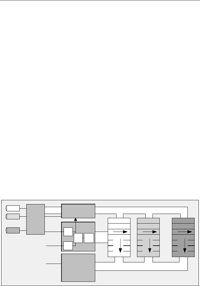
3.3 Sequential Recording Techniques
Sequential recording, also known as „double kinetic mode“ [353] or „time-lapse
recording“, adds one or two additional dimensions to the photon distributions
recorded by multidetector operation and multiplexing. Controlled by its internal
clock oscillator, the sequencer switches through a specified number of memory
blocks. Each memory block contains the photon distributions of all detectors and
multiplexing channels. Sequential recording in a multidetector system is illustrated
in Fig. 3.7. For sake of simplicity, multiplexing has been omitted.
The sequence may be started with a simple „start measurement“ command. How-
ever, in practice what is to be recorded is usually the response of the investigated
system to a stimulation event. The stimulation can be a strong laser pulse, a tempera-
ture jump, a change in an electric field applied across the sample, or the switch-on of
the excitation source. Usually, therefore, it is better to start the recording by a trigger
pulse that coincides with the stimulation. After being started, the sequencer steps
through a defined (usually large) number of memory blocks. Each block contains a
full photon distribution over the time in the signal period, t, several detector chan-
nels, and (not shown in Fig. 3.7) several multiplexing channels.
measure-
Start
Stop
CFD
CFD
from laser
Time
t
Channel register
Experiment
Trigger
Reference
Sequencer
latch
ment
ADC
TAC
Channel Channel
PMT 1
.
.
.
.
.
PMT 2
PMT n
Router
T
Dis.Cnt
Time from experiment trigger
t
T
Detector 1
t
T
Detector 2
t
T
Detector n
Fig. 3.7 Sequential recording. Triggered by the experiment trigger, the sequencer switches
through a large number of memory blocks. Each block contains the photon distribution over
the time in the signal period, t, over the detector channels, and (not shown) over possible
multiplexing channels
36 3 Multidimensional TCSPC Techniques
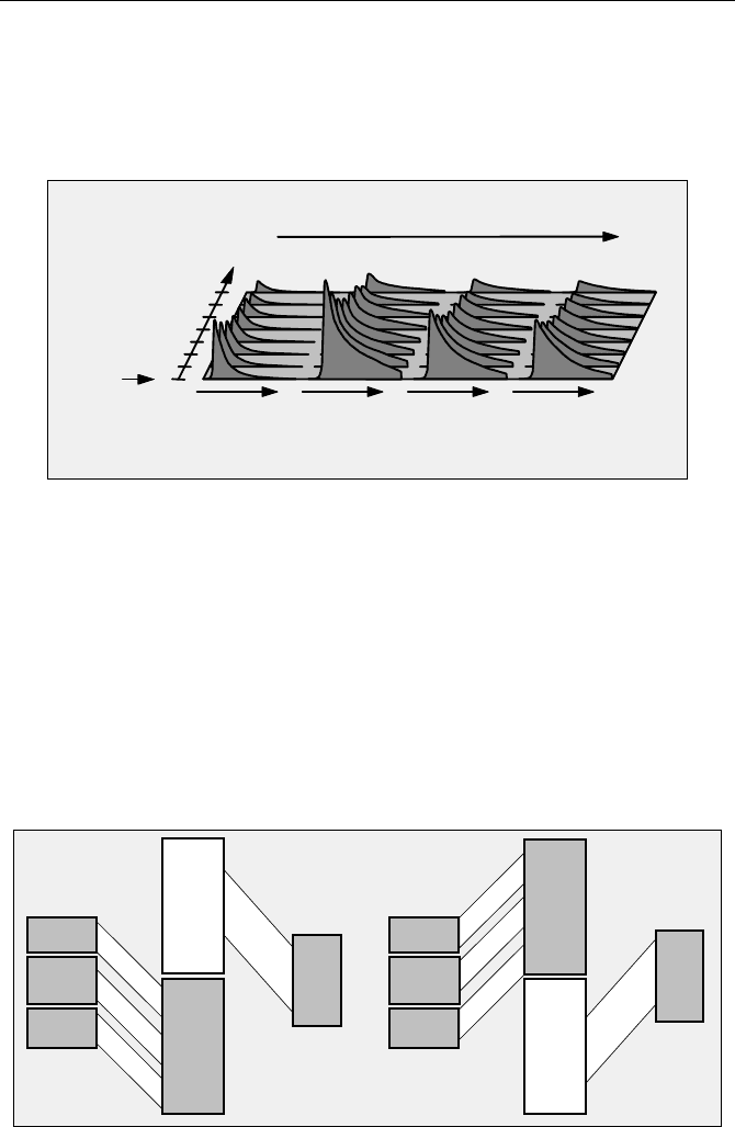
If the stimulation of the system under investigation is repeatable a large number
of triggered sequences can be accumulated. With accumulation, a sufficient num-
ber of photons per step is obtained even for sequencing rates faster than the count
rate. The different time scales are illustrated in Fig. 3.8. Again, multiplexing was
omitted for simplicity.
Detector 1 Detector 2 Detector 3 Detector 4
Time in
Sequence
Trigger
Experiment
Detector Channel
1
2
3
4
5
6
7
0
Time in signal
period
Time in signal
period
Time in signal
period
Time in signal
period
T
ttt t
Fig. 3.8 Triggered recording of a sequence of data blocks
Because the sequence is controlled by the TCSPC hardware, it is possible to
achieve extremely fast and accurate stepping, down to less than a microsecond per
data block. Of course, sequential recording can also be achieved by software control
of a TCSPC device, and advanced TCSPC devices in fact include operating modes
for recording software-controlled sequences. However, modern computers are far
from being real-time systems. Stepping faster than 100 ms per step becomes inaccu-
rate, which makes an accumulation of software-controlled sequences impossible.
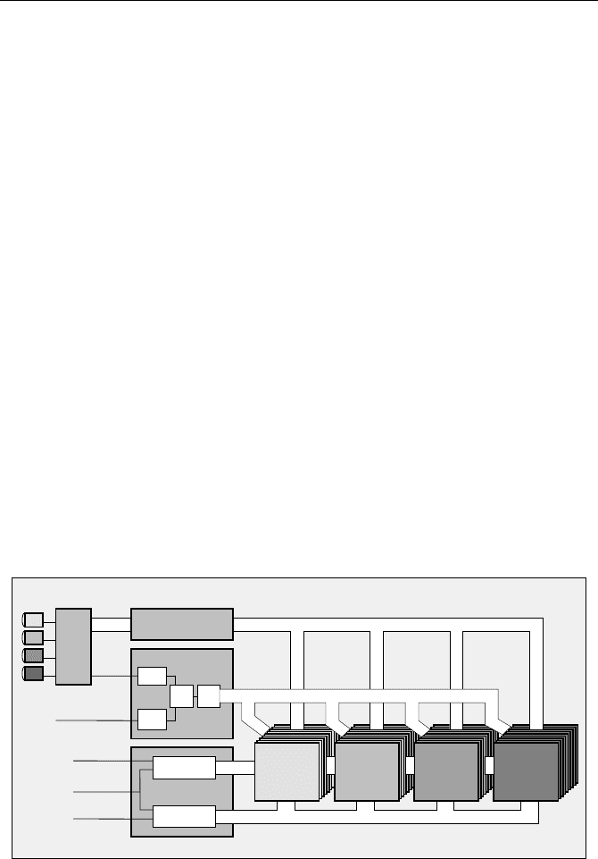
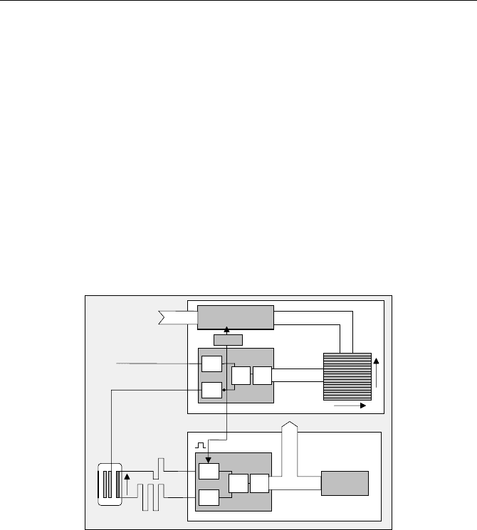
In some TCSPC devices a „Continuous Flow“ mode is implemented to record a
virtually unlimited number of waveforms. The sequencer of the continuous-flow
mode uses two independent data memory banks; see Fig. 3.9. After a trigger pulse
Time
Channel
register
Measure-
Sequencer
ment
Memory
Bank 2
Memory
Bank 1
Bus
Inter-
Readout
Memory
Bank 2
Readout
face
Bus
Inter-
face
Time
Channel
register
Measure-
Sequencer
ment
Memory
Bank 1
Fig. 3.9 Unlimited sequential recording by memory
b
ank swapping. When one memory
b
ank is full, the sequencer swaps the banks. While the sequencer writes into one bank, the
other one is read by the computer
3.4 Scanning Techniques 37
or a start command by the operator, the sequence starts in the first memory bank.
The sequencer switches through the memory blocks of the current bank. Again,
each memory block provides space for a full photon distribution versus the time in
the signal period, and the detector and multiplexing channel numbers. When the
current memory bank is full, the sequencer swaps the memory banks and contin-
ues recording. While the measurement is running in one memory bank, the results
of the other bank are read and stored to the hard disk. Thus, a virtually unlimited
number of decay curves can be recorded without any time gaps between subse-
quent steps of the sequence [31].
The „Continuous Flow“ mode is useful in all applications which require a large
number of curves to be recorded in time intervals down to the 100 us scale. Typi-
cal applications are dynamic brain imaging by diffuse optical tomography (DOT)
[328], and single-molecule detection in a capillary gel electrophoresis setup [31].
The continuous flow mode can also be used with a trigger signal that starts ei-
ther the recording of each bank or the recording of each data block within the
current bank. The continuous flow mode, with bank or data block triggering, is an
efficient and convenient technique for slow-scan systems. Trigger pulses from the
scanning device synchronise the recording with the scanning, and the data are
continuously read from the TCSPC module without stopping the scan.
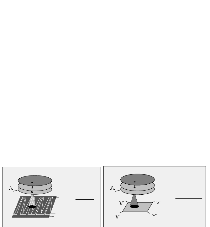
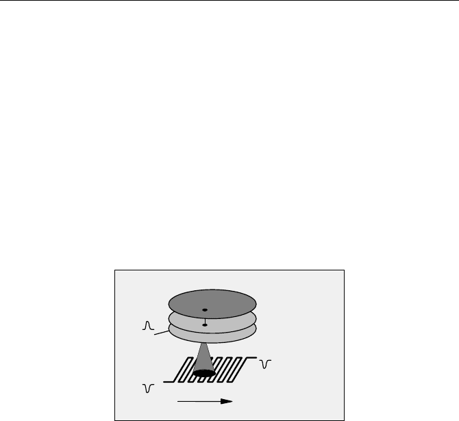
3.4 Scanning Techniques
In conjunction with an external optical scanner, a sequencer can be used to acquire
time-resolved images [33, 38, 147]. The principle is shown in Fig. 3.10.
Measure-
Frame clock
Line clock
Pixel clock
Start
Stop
Scanning
x
CFD
TAC
ADC
CFD
Scanner
from Laser
Time
Counter Y
Counter X
Detector 2 Detector 3 Detector 4
Location in scanning area
from
y
Detector 1
Time in pulse periodt
Channel / WavelengthChannel
Detectors
Channel register
Interface
n
Router
Photon
distribution
Photon
distribution
Photon
distribution
Photon
distribution
ment
or
to Scanner
Fig. 3.10 Image acquisition by synchronising the recording with an external scanner. Data
acquisition is synchronised with the scanning via the frame clock, line clock, and pixel
clock pulses. For each detector, a stack of images for consecutive times in the laser pulse
sequence is built up

38 3 Multidimensional TCSPC Techniques
The sequencer is configured as a scanning interface. It contains two counters,
X,Y, for the x and y location in the scanning area. Synchronously with the scan-
ning action, the sequencer counts through x and y. Synchronisation is achieved by
the scan clock pulses, frame clock, line clock, and pixel clock. The sequencer can
work either in an active mode, i.e. control a scanner, or in a passive mode, i.e. be
controlled from a free-running scanner.
In the active mode the sequencer runs a time-controlled sequence through the
pixels and lines of the image, and sends the frame clock, line clock, and pixel
clock pulses to the scanner. The active mode is called „Scan Sync Out“ and is
often used for slow-scan imaging in conjunction with piezo scan stages.
Scan Sync Out can be combined with multidetector operation and multiplexing.
Of course, the memory size of the TCSPC module limits the number of detector
and multiplexing channels and the number of pixels in the image .
Another active mode, called „Scan XY Out“ sends digital position signals to a
scanner. This simplifies the control of a scan stage considerably. Due to the lim-
ited number of signal input and output lines, multidetector operation and multi-
plexing are usually not applicable.
In the passive mode the sequencer receives the clock pulses from the scanner.
The pixel clock is used as the clock for the X counter, the line clock as the clock
for the Y counter. The X counter is reset by the line clock, the Y counter by the
frame clock. Practical implementations of scanning sequencers include additional
prescalers for pixel and line binning, and additional counter control logic for re-
cording selectable parts of a scan area. The passive imaging mode of the se-
quencer is often called „Scan Sync In“ mode. The Scan-Sync-In mode can be
combined with multidetector operation and multiplexing. The size of the image
and the number of detector and multiplexing channels are limited by the memory
space in the TCSPC module.
The Scan-Sync-In mode has become a standard fluorescence lifetime imaging
(FLIM) technique in confocal and two-photon laser scanning microscopes [33, 36,
38, 62, 147, 161, 282]. These microscopes use optical beam scanning with pixel
dwell time in the microsecond range and below. Several individual detectors or
channels of a multianode PMT detect the fluorescence in different wavelength
intervals. In the typical applications the pixel rate is higher than the photon count
rate. This makes the recording process more or less random. When a photon is
detected, the TCSPC device measures its time in the laser pulse period, t, and
determines the detector channel number (i.e. the wavelength of the photon) and
the current beam position, x and y, in the scanning area. These data are used to
build up the photon distribution over t, n, x, and y. As shown in Fig. 3.10, the
result can be interpreted as a number of data blocks for different wavelength, each
containing a stack of images for different times in the laser pulse sequence.
The scan rate in the Scan-Sync-In mode is determined essentially by the scan-
ner. Therefore, the scan rate, zoom, or region of interest selected in a scanning
microscope automatically acts on the TCSPC recording. Scanning can simply be
started und continued until a sufficient number of photons has been collected.
Of course, the Scan Sync In mode is not restricted to confocal and two-photon
laser scanning microscopy or high-speed scanning. Due to the simple interfacing
with the scanner, it can be used for other scanning applications as well [454].
3.5 Imaging by Position-Sensitive Detection 39
3.5 Imaging by Position-Sensitive Detection
Imaging by scanning techniques has its benefits, such as relatively simple imple-
mentation of multiwavelength detection and optical sectioning by confocal detec-
tion or two-photon excitation. Nevertheless, parallel acquisition of time-resolved
images is desirable for a number of applications.
Parallel image acquisition is, in principle, possible by two-dimensional mul-
tianode PMTs. The anode elements are connected to a standard routing device,
and the photons are recorded as described above under Sect. 3.1, page 29. How-
ever, the number of amplifiers and discriminators in the router increases with the
number of anode elements. Power consumption and space requirements restrict
the number of pixels that can be obtained this way. The practical limit is some-
where between 16 and 64. An array of 64 pixels cannot really be considered an
image.
Techniques Based on Charge Division
Almost continuous position information can be obtained from an MCP-PMT with a
resistive anode or with a micromachined wedge-and-strip geometry [247, 248, 262,
312] (see also Sect. 6, page 213). The detector principles are shown in Fig. 3.11.
Multichannel
plates
Cathode
A1
A2
A3
Timing
X =
Y =
A1 + A2 + A3
A1 + A2 + A3
A3
A1
Multichannel
Plates
Cathode
A1
A2
A3
A4
X =
Y =
A1+A2+A3+A4
A1+A2+A3+A4
A1+A2 - A3+A4
A1+A3 - A2+A4
Timing
Fig. 3.11 Principles of position-sensitive single-photon detectors based on charge division
The position is calculated by the ratio of the pulse amplitudes (or charge) meas-
ured at the outputs of the anode structure. Timing information is available from
the pulse at the last dynode or at the low-voltage side of the multichannel plate
(see also Sect. 6.1.3, page 215). Once the position information is available, the
task is reduced to multidetector operation in a large number of detector channels.
Unfortunately, transforming the outputs of the detectors into X- and Y-propor-
tional address words of a multidimensional TCSPC system is anything but simple.
In principle, the sums, differences, and quotients of the signals can be calculated
in analog circuits containing operational amplifiers and dividers [262]. The results
are converted by two ADCs, and the output bytes of the ADCs are sent to the
TCSPC routing input. Unfortunately a circuit like this is very slow, since the dy-
namic range of the signals (A1 to A4) is very large. For a spatial resolution of
100 u 100 pixels the signals A1 to A4 vary in a range of 1:100. Moreover, the
amplitude of the single-photon pulses themselves may vary by 1:10, so that the

40 3 Multidimensional TCSPC Techniques
overall dynamic range is 1:1,000. Analog dividers of a dynamic range this high
cannot be made fast. Therefore the maximum count rate that can be expected from
a system like this is of the order of 10
5
s
1
.
A second approach is to use FIFO operation (see Sect. 3.6, page 43). The sig-
nals A1 to A4 are converted directly by four ADCs. The converted values for A1
to A4 and the TAC times for the individual photons are stored in a file. The image
is built up off-line by analysing the recorded data. The problem of this approach is
the huge amount of data that has to be transferred over the computer bus and
stored on a hard disc. Given a data word size of 12 bit for A1 through A4, and
12 bit for the TAC time, 60 bits or 8 bytes per photon are required.
Another possible approach is to convert the signals A1 to A4 directly, and to
calculate the quotients in a digital divider structure. However, digital division is
time-consuming as well. A possible solution to the processing-time problem is the
system architecture shown in Fig. 3.12.
measure-
Start
Stop
CFD
CFD
from laser
Time
Experiment
Scan Clocks
etc.
Trigger
Reference
Sequencer
ment
ADC
TAC
T time in sequence
A1
A2
A3
A4
Timing
Pipelinet time
Photon
distribution
Sequencer
step 1
Photon
distribution
Sequencer
step2
Photon
distribution
Sequencer
step n
ADC
ADC
ADC
ADC
Multiplexing
Mpx. channel 1 Mpx. channel 1 Mpx. channel 1
Mpx. Channel Mpx. Channel
Photon
distribution
Sequencer
step 1
Photon
distribution
Sequencer
step2
Photon
distribution
Sequencer
step n
Mpx. channel 2 Mpx. channel 2 Mpx. channel 2
X, Y Position of photon
Digital
Arithmetic
Unit
Processing in
Pipeline
Fig. 3.12 TCSPC system for position-sensitive detection by detectors based on charge
division
The timing pulse from the multichannel plate is processed in the usual way in
the time-measurement block. The pulses from the anode structure of the detector,
A1 through A4, are converted by four ADCs on the TCSPC board. The position of
the photon is calculated in a digital arithmetic unit. The unit has to deliver one
X Y data pair within 100 ns or less to keep the dead time within the common stan-
dard of advanced TCSPC. The solution to the problem is „pipelining“:
The time-consuming step in the calculation of the position is the division. Digi-
tal division is a multistep procedure, which requires as many steps as there are
result bits. Therefore, the throughput can be increased by using a structure of par-
allel dividers. The fist divider runs the first division step for the current photon,
the second divider the second step for the previous photon, and so on. A 12-bit
quotient appears at the output of the pipeline 12 photons later. A single step of the
division can be performed within less than 100 ns. Therefore, after a delay of 12
photons, any next quotient is available within 100 ns. The pipeline delay in the
3.5 Imaging by Position-Sensitive Detection 41
divider must, of course, be compensated for by a similar pipeline at the output of
the time-measurement system.
In principle, parallel imaging can be combined with multiplexing and sequenc-
ing. Of course, the size (or pixel number) of the images, sequencer steps, and
multiplexing channels that can be used simultaneously are limited by the memory
space in the TCSPC module.
The architecture shown in Fig. 3.12 is similar, but not identical with the general
architecture of multidimensional TCSPC devices. However, the architecture
shown in Fig. 3.12 can be used for a whole family of detectors; see also
Sect. 6.1.3, page 215.
Techniques Based on Pulse Delay
A second principle of position-sensitive detection is based on MCPs with delay-
line anodes [3, 254]. The principle of these detectors is shown in Fig. 3.13.
Multichannel
Plates
Cathode
Timing
A1
A2
x
D
Fig. 3.13 MCP with delay-line anode. The position is derived from the delay between A1
and A2
The position along the delay line is derived by measuring the delay between the
single-photon pulses at both outputs of the delay line. For two-dimensional detec-
tion two perpendicular, semitransparent delay lines can be used. The total transit
time of the delay line is about 10 ns. Consequently a time resolution of about
40 ps is required to obtain a spatial resolution of 256 pixels along the delay line.
This resolution is well within the reach of a standard TCSPC device, but at the
very limit of a simple TDC chip (see Sect. 4.2.2, page 55). Therefore, the re-
cording system usually requires two or three complete TCSPC channels. One
determines the time between the single-photon pulse at the dynode output, D, and
the reference pulse from the laser. The second and the third TCSPC channel
measures the time between the single-photon pulses at A1 and A2 of the delay-
lines. The benefit of the delay-line PMT is that the location can be derived directly
from the delay of the pulses. No analog or digital division is required, as in the
case of charge division.
Either the TCSPC channels can be operated in the time-tag mode (see Sect. 3.6,
page 43) or the ADC result of the second and third TCSPC channel can be used as
a routing signal for the first one.
42 3 Multidimensional TCSPC Techniques
Time-tag recording means that the TCSPC channels do not build up a photon
distribution but store each individual photon with its TAC time („micro time“) and
its time from the start of the experiment („macro time“). The computer calculates
the photon distribution at each location along the delay line and the time in the
signal period. Time-tag recording of delay line data requires that the macro time
clocks of all TCSPC channels be synchronised. Even then it is difficult to assign
the data in the position channel to the correct data in the time channel. Due to
slightly different CFD thresholds and different dead times, a photon recorded in
the position channel need not necessarily be recorded in the time channel, and vice
versa. To avoid misinterpretation of the data, a macro time resolution of 50 ns or
finer is required.
Routing the photons by the ADC result of a second TCSPC channel faces simi-
lar problems. It must be guaranteed that the position information is derived from
the same photon as the time information. This is possible by gating the start CFD
of one TCSPC channel with the detection of a photon in the other. The principle is
shown in Fig. 3.14.
CFD
Start
Stop
CFD
Channel register
ADC
CFD
Start
Stop
CFD
ADC
TAC
Gate
20ns
Delay 1
Delay 2
to channel register
of TCSPC channel 1
from TCSPC
channel 2
Position
Position
Time
Memory
position
TCSPC
channel 1
TCSPC
channel 2
from Laser
Memory
channel 2
channel 1
Detector
Delay
t
x
x
TAC
Fig. 3.14 TCSPC system for delay-line detector
TCSPC channel 1 measures the time of the photons in the laser pulse sequen-
ce. It uses the pulse from the low-voltage side of the multichannel plate, which
does not depend on the location of the photon. TCSPC channel 2 measures the
time between the two ends of the delay-line anode of the detector. The start CFD
of channel 2 is gated by the output pulse of the CFD of channel 1. The start
pulse of channel 2 is delayed by 10 ns. Consequently, channel 2 starts only for
photons that are detected in channel 1. The ADC result of TCSPC channel 2 is
used as a channel input signal of TCSPC channel 1. The signal is latched into
the channel register after a delay that corresponds to the conversion time of
TCSPC channel 2. In the memory of TCSPC channel 1 the photon distribution
over t and x builds up. TCSPC channel 2 actually does not need a memory. How-
ever, a memory is convenient for building up and displaying the photon distribu-
tion versus the x coordinate.

3.6 Time-Tag Recording 43
3.6 Time-Tag Recording
A variation of the TCSPC technique does not build up photon distributions but
stores information about each individual photon. The mode is called „time tag“,
„time stamp“, „list“, or „FIFO“ mode. For each photon, the time in the signal
period, the channel word, and the time from the start of the experiment, or „macro
time,“ is stored in a first-in-first-out (FIFO) buffer. During the measurement the
FIFO is continuously read, and the photon data are stored in the main memory or
on the hard disc of a computer.
The structure in the time-tag mode is shown in Fig. 3.15. It contains the channel
register, the time-measurement block, a „macro time“ clock, and the FIFO buffer
for a large number of photons. It has some similarity to the multidimensional
TCSPC described in the paragraphs above. In fact, many advanced TCSPC mod-
ules have both the photon distribution and the time-tag mode implemented, and
the configuration can be changed by a software command [25]. The sequencer
then turns into the macrotime clock, and the memory turns into the FIFO buffer.
measure-
Stop
CFD
CFD
from laser
Time
Time in signal
t
Channel register
Experiment
Trigger
Reference
clock
latch
ment
ADC
TAC
Channel
T Macro time
Readout
by
Computer
period
Start
PMT 1
.
.
.
.
.
PMT 2
PMT n
Router
Dis.Cnt
Detector
ControlExt. Control
channel
Macro-time
FIFO Buffer
Fig. 3.15 Architecture of a TCSPC module in the FIFO mode
When a photon is detected, the „micro time“ in the signal period is measured by
the time-measurement block. Simultaneously the detector channel number for the
current photon and often a number of additional bits from external experiment
control devices are written into the channel register. The „macro time“ clock de-
livers the time of the photon from the start of the experiment. All these data are
written into the FIFO.
The output of the FIFO is continuously read by the computer. Consequently,
the time-tag mode delivers a continuous and virtually unlimited stream of photon
data. It is, of course, imperative that the computer read the photon data at a rate
higher than the average photon count rate. However, modern operation systems
are multitask systems, and it is unlikely that the computer reads the FIFO continu-
ously. Moreover, in typical applications bursts of photons appear on a background