Barber J.R. Intermediate Mechanics of Materials
Подождите немного. Документ загружается.

12.4 Indeterminate problems 525
12.4 Indeterminate problems
Indeterminate problems for axially loaded beams are treated in the same way as
classical indeterminate beam bending problems. The redundant reactions are carried
through the analysis as additional unknowns until the kinematic boundary conditions
are imposed, at which point it will be found that there are just sufficient equations to
determine the unknowns.
Figure 12.11: An indeterminate stability problem
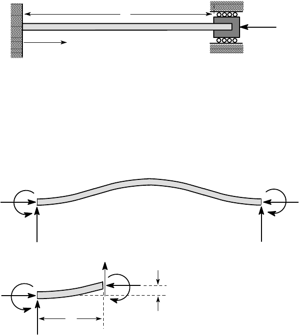
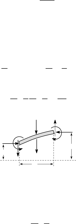
Consider, for example, the beam of Figure 12.11, which is built in at z = 0 and
constrained so as to have zero slope and lateral deflection at z = L. The free-body
diagram of the buckled beam is shown in Figure 12.12 (a), from which we note
that there are two unknown reactions R
1
,R
2
and two unknown restraining moments
M
1
,M
2
. Equilibrium conditions provide only two equations for these four unknowns,
so the problem is indeterminate.
(a)
P
P
M
1
R
1
M
2
R
2
(b)
P
P
M
u(z)
V
z
M
1
R
1
Figure 12.12: Free-body diagram of (a) the complete beam and (b) a beam segment
The free-body diagram of a beam segment is shown in Figure 12.12 (b), from
which we conclude that
M = M
1
+ Pu −R
1
z .
Substitution in the bending equation then yields the governing equation
P
L
z
526 12 Elastic Stability
d
2
u
dz
2
+
Pu
EI
= −
M
1
EI
+
R
1
z
EI
.
The general solution of this ordinary differential equation is
u = −
M
1
P
+
R
1
z
P
+ A cos
λ
z + Bsin
λ
z
and the four kinematic boundary conditions
u =
du
dz
= 0 ; z = 0 and L
define a set of four homogeneous algebraic equations for the four unknowns M
1
,R
1
,
A,B. A non-trivial solution requires that the determinant of the coefficients of these
equations be zero, leading to an eigenvalue equation for the critical force P
0
. The
completion of this example is left as an excercise for the reader.
12.5 Suppressing low-order modes
We remarked in §12.1 that the buckling force can be increased by the judicious
placement of intermediate supports. The best location for these supports can be
determined by solving the original stability problem and examining the lowest or-
der eigenfunctions or modes of the solution.
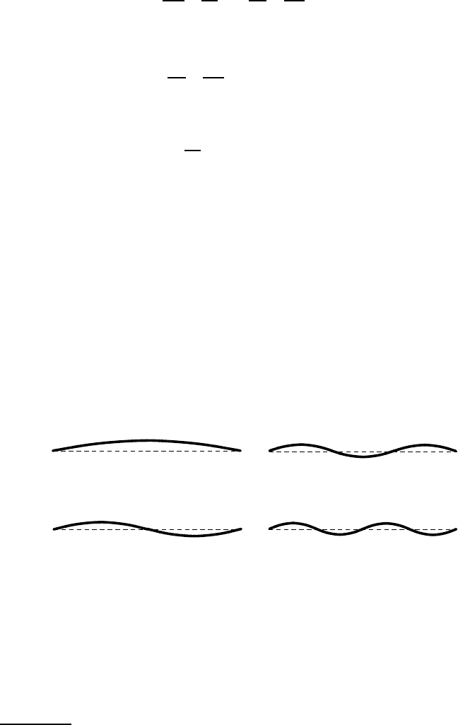
5
The first four eigenfunctions for the
simply-supported beam are shown in Figure 12.13.
Figure 12.13: First four eigenfunctions for the simply supported beam of Figure
12.2(a)
Notice how the displacement for the first eigenfunction has the same sign
throughout the beam, whereas for the higher order eigenfunctions there are points,
known as nodes, where the displacement changes sign. In general, the nth eigenfunc-
tion has (n−1) nodes, not counting the end points.
If additional supports are placed at each of the (n−1) nodes of the nth eigenfunc-
tion, the first (n−1) buckling modes will be suppressed and buckling will first occur
5
i.e. the deformed shapes corresponding to the first few buckling forces.
12.5 Suppressing low-order modes 527
at the force corresponding to the nth eigenvalue. Furthermore, no reactions will be
induced at these supports, even when buckling occurs. By contrast, if (n−1) supports
are placed at any other locations, then (i) the buckling force will be lower than the nth
eigenvalue and (ii) reactions will be induced at the supports once buckling occurs.
For these reasons, it is clear that the optimum location for the supports is at
the nodes of the first acceptable eigenfunction. Since the additional supports do not
carry any load, they do not need to be particularly strong. However, their stiffness
is important, if they are to perform the function of suppressing low order modes.
In general, there is a certain minimum stiffness required, beyond which there is no
further advantage in increasing the support stiffness. These results and the method of
solution are best illustrated by example.
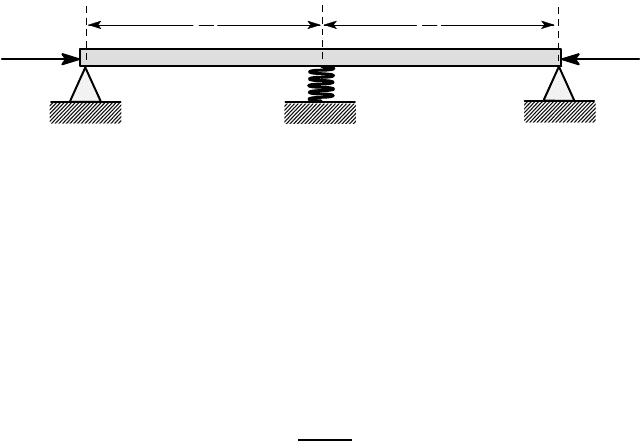
Example 12.3
Figure 12.14 shows a simply-supported beam of length L and flexural rigidity EI,
loaded by an axial force P. It is proposed to increase the buckling force by providing
an additional support at the mid-point, which can be modelled as a spring of stiff-
ness k. Find the buckling force as a function of k and hence determine the minimum
stiffness for the support if the first buckling mode is to be suppressed.
Figure 12.14: Simply supported beam with an elastic central support
The system is symmetric about the mid-point and in such cases the eigenfunc-
tions are always either symmetric or antisymmetric — in other words, in any given
mode, the displacements of symmetric points are always either equal or equal and
opposite. Reference to Figure 12.13 shows that the eigenfunctions of the simply sup-
ported beam are alternately symmetric and antisymmetric.
The mid-point must be a node for any antisymmetric mode, so these modes are
unaffected by the addition of a central support. In the present case, the lowest anti-
symmetric mode is that of Figure 12.5, corresponding to the critical force
P
1
=
4
π
2
EI
L
2
,
from equation (12.16).
The symmetric modes are affected by the flexible support, but the symmetry per-
mits some simplification in the analysis. Figure 12.15 (a) shows a symmetric mode
and the corresponding free-body diagram is shown in Figure 12.15 (b).
P
P
k
L
2
L
2
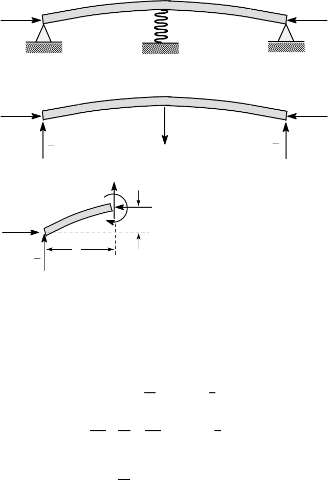
528 12 Elastic Stability
(a)
(b)
P
P
F
F
2
F
2
(c)
P
P
u(z)
z
V
M
F
2
Figure 12.15: (a) Symmetric buckling mode; (b) free-body diagram for the whole
beam and (c) for a beam segment
The spring exerts an unknown resisting force F and by symmetry and equilib-
rium, the two reaction forces must both be equal to F/2. Also by symmetry, the
slope of the beam du/dz must be zero at the mid-point z=L/2. These results permit
us to solve the problem by considering only the left half of the beam.
The free-body diagram of a beam segment is shown in Figure 12.15 (c), from
which we find
M = Pu −
Fz
2
; 0 < z <
L
2
and hence
d
2
u
dz
2
+
Pu
EI
=
Fz
2EI
; 0 < z <
L
2
.
The general solution of this equation is
u =
Fz
2P
+ A cos
λ
z + Bsin
λ
z
and the unknowns A,B,F are determined from the two kinematic boundary condi-
tions
P
P
12.5 Suppressing low-order modes 529
u = 0 ; z = 0
du
dz
= 0 ; z =
L
2
and the constitutive relation for the spring
F = ku
L
2
.
These conditions yield the simultaneous equations
A = 0
F
2P
−A
λ
sin
λ
L
2
+ B
λ
cos
λ
L
2
= 0
F
L
4P
−
1
k
+ A cos
λ
L
2
+ B sin
λ
L
2
= 0 ,
which have a non-trivial solution if and only if the determinant of the coefficient
matrix is zero — i.e.
1
2P
sin
λ
L
2
=
λ
L
4P
−
1
k
cos
λ
L
2
and hence
tan
r
PL
2
4EI
=
r
PL
2
4EI
1 −
4P
kL
.
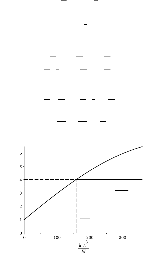
The buckling force, P
0
is plotted as a function of the dimensionless support stiffness
kL
3
/EI in Figure 12.16.
P
0
L
2
π
2
EI
P
0
=
4
π
2
EI
L
2
1st mode (2nd mode)
k
0
L
3
EI
Figure 12.16: Buckling force as a function of support stiffness
530 12 Elastic Stability
As we should expect, the first symmetric buckling force is given by the elemen-
tary result P
0
=
π
2
EI/L
2
for k=0 (no central support) and it increases monotonically
with k, reaching the buckling force P
1
for the first antisymmetric mode when
k = k
0
=
16
π
2
EI
L
3
.
Use of a support for which k > k
0
would have no effect on the buckling force, since
buckling would then occur in the antisymmetric mode at P= P
1
.
12.6 Beams on elastic foundations
The buckling behaviour is qualitatively changed if a beam is supported on an elas-
tic foundation. Figure 12.17 shows a small segment of such a beam [compare with
Figure 7.3 (b)] and we conclude from equilibrium arguments that
dV
dz
= w(z) + ku(z) ;
dM
dz
= P
du
dz
+V . (12.22)
Eliminating V, M between these equations and the beam bending equation M =
−EId
2
u/dz
2
, we obtain the governing equation
d
4
u
dz
4
+
P
EI
d
2
u
dz
2
+
ku
EI
= −
w(z)
EI
. (12.23)
P
P
M(z)
V(z)
M(z + δz)
V(z + δz)
w(z) δz
k u(z) δz
δz
u(z)
u(z + δz)
Figure 12.17: Equilibrium of a beam segment
If there is no lateral load [w(z)= 0], the solution of equation (12.23) is obtained
as in §7.2 by assuming a solution in the form
u(z) = Ae
bz
, (12.24)
where A,b are constants. Substituting into (12.23), we then obtain the algebraic equa-
tion
b
4
+
Pb
2
EI
+
ku
EI
= 0 (12.25)
12.6 Beams on elastic foundations 531
and hence
b
2
=
1
2
−
P
EI
±i
s
4k
EI
−
P
EI
2
, (12.26)
which can be written in the form
b
2
=
ρ
e
±i
θ
, (12.27)
where
ρ
2
=
1
4
"
P
EI
2
+
4k
EI
−
P
EI
2
#
=
k
EI
(12.28)
and
cos
θ
= −
P
ρ
EI
= −
P
√
4kEI
. (12.29)
After some algebra, the four solutions for b can be written
b = ±
β
1
±
β
2
i , (12.30)
where
β
1
=
4
r
k
4EI
s
1 −
P
√
4kEI
;
β
2
=
4
r
k
4EI
s
1 +
P
√
4kEI
. (12.31)
The general homogeneous solution of (12.23) is therefore
u
H
(z) = B
1
e
β
1
z
cos(
β
2
z) + B
2
e
β
1
z
sin(
β
2
z) + B
3
e
−
β
1
z
cos(
β
2
z)
+ B
4
e
−
β
1
z
sin(
β
2
z) . (12.32)
Comparison with Chapter 7 shows that this reduces to equation (7.11) in the
limiting case where P = 0. Two of the functions in (12.32) grow with z and two
decay, leading to a state in which the deformation is localized near the ends of the
beam, as in §7.2.1, if the beam is sufficiently long. However,
β
1
→0 as P→P
0
, where
P
0
=
√
4kEI . (12.33)
Thus, as P approaches P
0
, the decay rate of the end disturbance gets slower until at
P = P
0
there is no decay and end effects penetrate all along the beam. Notice that P
0
is also the value of P at which the algebraic equation (12.25) has two identical roots.
For an infinite beam, there are no end conditions and at P = P
0
there exists a
non-trivial solution of the homogeneous equation of the form
u(z) = A cos(
β
0
z) + B sin(
β
0
z) , (12.34)
where A,B are arbitrary constants and
β
0
=
4
r
k
EI
. (12.35)
532 12 Elastic Stability
Thus, for a sufficiently long beam, P
0
is the first buckling force and the buckling
mode is of sinusoidal form with wavenumber
β
0
. This contrasts with the unsupported
beam, where the wavenumber and hence the buckling force both depend on the length
L [see equations (12.11, 12.13)].
The buckling force for a finite beam will also be P
0
if the length is an integer
multiple of the half-wavelength
π
/
β
and the ends are simply supported. In other
cases, the buckling force will generally be increased by the end constraints, but this
increase will be very small if
β
L ≫1. For shorter beams, the solution proceeds as in
§12.1, but using (12.32) in place of (12.4).
12.6.1 Axisymmetric buckling o f cylindrical shells
We saw in Chapter 9 that the axisymmetric bending of cylindrical shells is governed
by the same equation as that for a beam on an elastic foundation. The buckling be-
haviour of these two systems is also closely related. We first need to modify the
equilibrium equation (9.16) to include the moment due to the axial force, obtaining
V =
dM
z
dz
−
P
2
π
a
du
r
dz
, (12.36)
where a is the mean radius of the shell and
P = −2
π
at
σ
1
(12.37)
is the total axial compressive force
6
applied to the cylinder.
Substituting this modified equation into (9.18) and rearranging terms, we obtain
a differential equation whose homogeneous form is
d
4
u
r
dz
4
+
P
2
π
aD
d
2
u
r
dz
2
+
Etu
r
Da
2
= 0 . (12.38)
Comparing this equation with (12.23) and remembering that the critical force corre-
sponds to the condition where the algebraic equation (12.25) has two identical roots,
we conclude that the buckling force P
0
for a long cylinder will be given by
P
0
2
π
aD
2
=
4Et
Da
2
(12.39)
and hence
P
0
= 4
π
√
EtD =
2
π
Et
2
p
3(1 −
ν
2
)
, (12.40)
using equation (9.14) for the stiffness D.
The corresponding critical axial membrane stress is
6
Remember that the moment and shear force in equation (9.16) are per unit circumference.
The axial force per unit circumference is P/2
π
a.
12.6 Beams on elastic foundations 533
σ
0
= −
P
0
2
π
at
= −
Et
a
p
3(1 −
ν
2
)
, (12.41)
and this will generally exceed the yield stress unless the shell is very thin t/a ≪1.
Also, a cylindrical shell loaded in compression will generally buckle first in a non-
axisymmetric mode (recall the experiment at the beginning of this chapter) unless
the axial force is applied in a way which constrains the ends of the cylinder to be
perpendicular to the axis.
Experiment
Take a short thin-walled tube with plane ends and compress it slowly and carefully
in a parallel jaw vice. If you align it carefully, you should be able to produce an
axisymmetric buckling mode. However, significant deformations will be produced at
the ends before the theoretical buckling force is reached and these will lead to plastic
deformation before the rest of the tube buckles. This leads to a form of deformation
as shown in Figure 12.18. The tube should then concertina up from the end as the
vice is closed. This experiment works best if the tube wall is not too thin, otherwise
non-axisymmetric modes tend to dominate the buckling behaviour. However, it is
also interesting to try compressing an aluminium beverage can, which has very thin
walls and also some quite complex end constraint due to the can end design.
P
Figure 12.18: Buckling of a cylindrical shell
12.6.2 Whirling of shafts
A closely related instability occurs in rotating shafts when the speed is sufficiently
high. Suppose that for some reason the shaft is deflected from the axis by a displace-
ment u(z) as shown in Figure 12.19.
z
u(z)
Ω
Figure 12.19: Deflected shape of the rotating shaft

534 12 Elastic Stability
As a result of the rotation, there will be an acceleration
Ω
2
u, where
Ω
is the ro-
tational speed. This will result in an equivalent outward inertia force w(z)=−m
Ω
2
u,
where m is the mass of the shaft per unit length. Notice that the force is proportional
to the local displacement, as in the case of a beam on an elastic foundation, but this
time the direction of the force is such as to exaggerate the deformation, which has an
inherently destabilizing effect.
Using the equations
dV
dz
= w(z) ;
dM
dz
= V ; M = −EI
d
2
u
dz
2
, (12.42)
we obtain
EI
d
4
u
dz
4
= −
d
2
M
dz
2
= −
dV
dz
= m
Ω
2
u
and hence
d
4
u
dz
4
−
m
Ω
2
u
EI
= 0 . (12.43)
This equation has the general solution
u(z) = B
1
e
γ
z
+ B
2
e
−
γ
z
+ B
3
cos(
γ
z) + B
4
sin(
γ
z) , (12.44)
where
γ
=
4
r
m
Ω
2
EI
. (12.45)
The fours constants B
1
= B
2
= B
3
= B
4
are determined from two boundary con-
ditions at the ends of the shaft. For example, if the beam is simply supported at the
end as in Figure 12.19, we have u= 0 and M =0. For a built in end, u =0 and u
′
=0,
whereas for a free end, M = 0 and V = 0. These conditions are all homogeneous
and the resulting simultaneous equations will therefore have only the trivial solution
B
1
= B
2
= B
3
= B
4
= 0 except when the determinant of coefficients is zero. This con-
dition defines the critical speed
Ω
0
, also known as the whirling speed. However, if
the shaft has some initial imperfection as in §12.2, the governing equation (12.43)
will be modified to include an inhomogeneous term and deflection will be produced
at all speeds. This can be quite significant even below the critical speed.
Example 12.4
A solid circular shaft of diameter D and length L is simply supported at its ends. Find
the critical rotational speed if the material has Young’s modulus E and density
ρ
.
The homogeneous solution is given by equation (12.44) and the corresponding
bending moment distribution is
M(z) = −EI
d
2
u
dz
2
= EI
γ
2
−B
1
e
γ
z
−B
2
e
−
γ
z
+ B
3
cos(
γ
z) + B
4
sin(
γ
z)
.
Imposing the boundary conditions