ASM Metals HandBook Vol. 8 - Mechanical Testing and Evaluation
Подождите немного. Документ загружается.

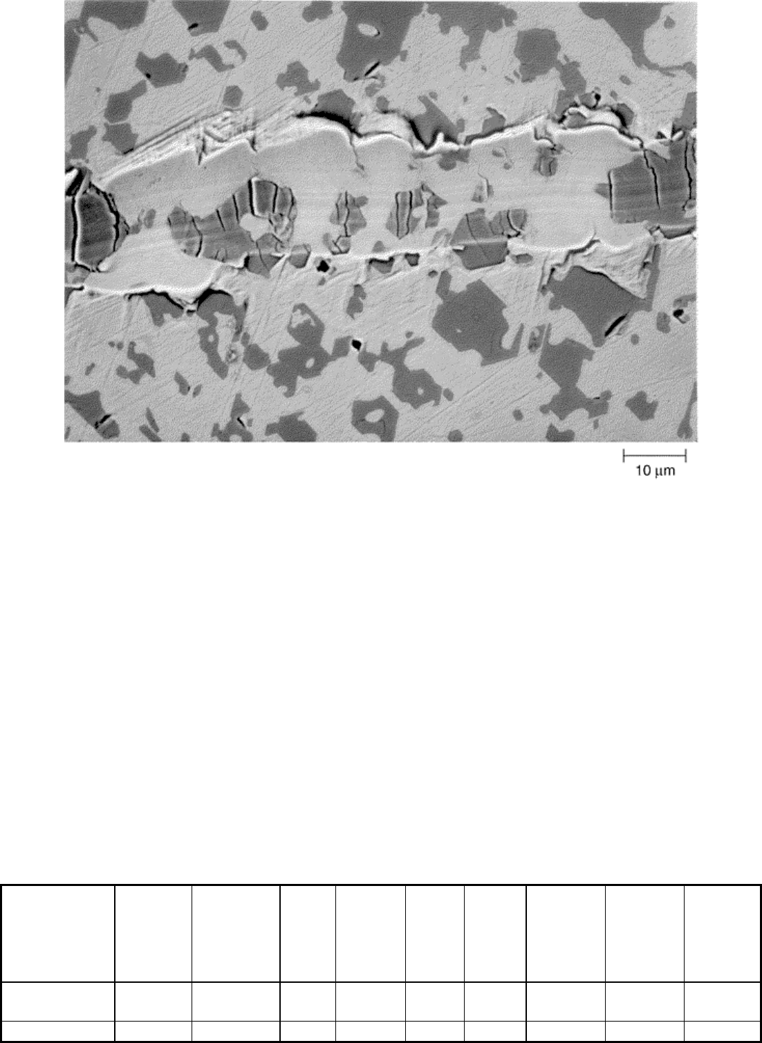
Fig. 2 Single scratch, using a 20 μm conical diamond stylus under a 100 g load, on a high-Cr white cast
iron. Notice the matrix transformation to martensite and the cracking of the carbides. Source: Ref 12
Dry Abrasion against Fixed Particles
Dry abrasion against fixed particles is typically performed using a pin abrasion wear tester. Pin abrasion wear
testing simulates high-stress, quasi-two-body abrasive wear. The wear test is high stress because the abrasive
grains are frequently fractured during the test. It is quasi-two-body because at the onset of the test, the abrasive
particles are fixed to the cloth backing with an adhesive. As the test progresses, fractured bits of the abrasive
and wear debris become trapped in the interfacial region between the end of the pin and the abrasive cloth, thus
adding a third body to the system.
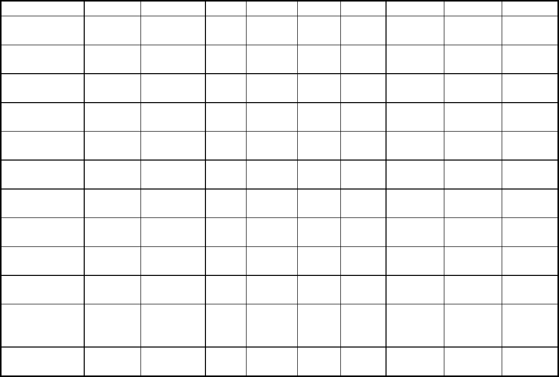
Many different pin abrasion wear testers have been developed over the years (Table 1). All these devices have
one thing in common; that is, they expose a specimen to an environment where the abrasive grains are initially
fixed to a substrate. Table 1 also provides some of the pertinent operating conditions for various pin abrasion
wear testers. ASTM G 132 provides a useful guide to the general features of pin abrasion wear testing (Ref 27).
In the discussion that follows, details specific to the operation of the pin-on-drum are provided (Fig. 3) (Ref 23,
28), although these same conditions also hold for many of the other pin abrasion wear testers.
Table 1 Comparison of various pin abrasion wear tests
Author(s)
(reference)
Machine
type
Geometry
of
wear
track
Pin
diam,
mm
Normal
load, N
Unit
load,
N/cm
2
Speed,
m/s
Abrasive
area, m
2
Total
available
path
length,
m
Pin
rotation,
rpm
Robin (13) Pin-on-
disk
Circular 15 12.4 9.8 1.14 N/A N/A No
Khruschov Pin-on-Spiral 2 2.9 94 0.5 0.05 45 No
(14) disk
Richardson
(15)
Pin-on-
disk
Spiral 2.5 4.9 100 0.17 0.05 20 No
Nathan and
Jones (16)
Pin-on-
belt
Linear 5 4.9–98 25–
500
0–2.5 0.36 70 Optional
Khruschov
(17)
Pin-on-
drum
Helical 2 Impact … … 0.06 25 No
Larsen-Basse
(18)
Pin-on-
table
Linear 9.5 0.98–
17.6
1.4–
25
N/A N/A N/A No
Muscara and
Sinnott (19)
Pin-on-
table
Rectilinear
6.35 66.7 210 0.042 0.10 15 20
Mutton (20) Pin-on-
drum
Helical 6.35 66.7 210 0.042 0.49 75 20
Allen et al.
(21)
Pin-on-
belt
Linear 10 4.9–98 5–98 0–0.45
0.72 15 No
Berns and
Fischer (22)
Pin-on-
table
Rectilinear
6 37.2 132 0.005 0.30 50 48
Blickensderfer
and Laird (23)
Pin-on-
drum
Helical 6.35 17.4–
103.4
54.9–
326.5
0.045 0.97 150 17
Sin et al. (24) Pin-on-
disk
Spiral 6.35 4.9–
39.2
15.5–
123.8
0.02–
0.06
0.03 4 No
Axén and
Jacobsson
(25)
Pin-on-
drum
Helical 5 × 5 0.9–
39.1
3.6–
156.4
0.08 N/A 7 No
Moore and
King (26)
Pin-on-
disk
Spiral 5 2.5–
29.5
12.5–
150.0
0.5 N/A 8 No
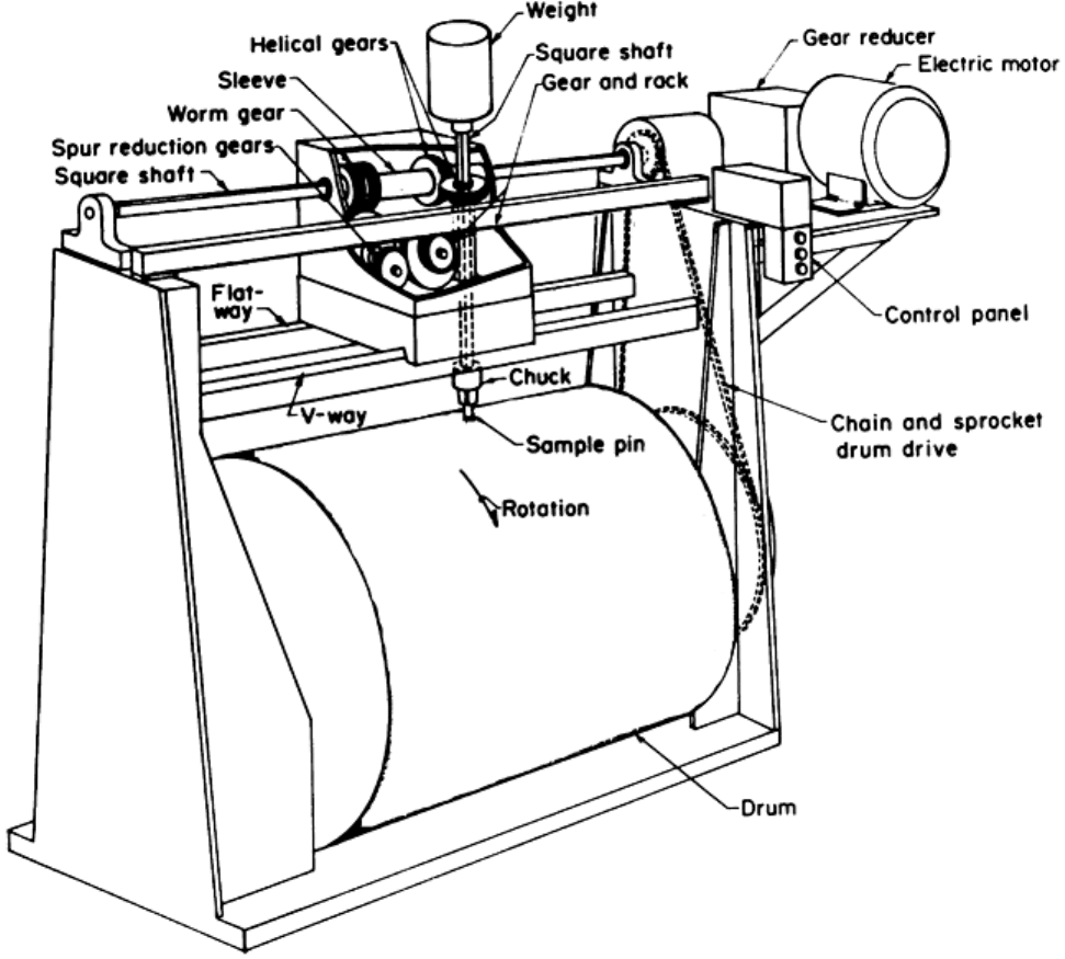
Fig. 3 Schematic diagram of the pin-on-drum wear apparatus. Source: Ref 23, 28
Selection of the Abrasive Media. Selecting the appropriate abrasive to use in the wear test is important. The
most common abrasive in the earth's environment is silica (SiO
2
), with a hardness of about 1000 HV. To more
closely simulate the actual abrasion that occurs in a particular application, however, the same type of abrasive
encountered should be used in the pin abrasion test. Commercially available abrasive cloths are produced with
garnet (1300 HV), alumina (2000 HV), and silicon carbide (2500 HV) as the abrasives. Sometimes flint
abrasives (common sandpaper) are used, although silicon carbide is probably the easiest abrasive particle to
find in the variety of paper sizes needed to fit on the pin abrasion testers.
Another consideration in abrasive selection is the amount of abrasive wear desired during the course of the
wear test, and this is a function of the abrasive used in the test, the sliding distance, and the hardness of the
material being investigated. For “soft” metals and alloys such as aluminum and mild steel, garnet, alumina, and
silicon carbide abrasive particles of the same size remove approximately the same mass of material during a test
of the same duration. Any minor variations in material removed when using these abrasives is due to slight
variations in the characteristics of the abrasive particles, such as their shape (angularity), their fracture
characteristics (sharp or blunt fragments upon fracture), and their packing on the backing cloth during
manufacture (different abrasive types pack differently on the cloth as a result of their shape). For “hard”
materials such as tool steels and high-chromium white cast iron, some change in the relative wear ranking may
occur when different abrasives are used (Ref 29). For hard-particle reinforced composites and ceramics, a
harder abrasive such as alumina or silicon carbide should be used in order to give reasonable mass losses for
reasonable sliding distance.
Pin Abrasion Test Procedures. During a pin abrasion test, a pin (of whatever diameter used for that particular
machine) is first broken in by running it across the abrasive to be used in the actual wear test. This act
accomplishes two purposes: it creates a uniform surface for testing and conforms the specimen surface to the
counterface. The pin specimen is cleaned and then weighed (typically to an accuracy of 0.1 mg). The actual
wear test is then performed, with the sliding distance being determined to give a reasonable amount of mass
loss, usually on the order of 20 to 40 mg. (This way, measurement errors are kept low, that is, 1 part in 200–
400.) Sometimes the sliding distance is determined by the physical constrains of the pin abrasion test apparatus
(especially for the phonograph-style or table machines). Once an abrasion test is completed, the specimens are
cleaned in some manner to remove any loosely adherent wear debris, rinsed in some manner to remove surface
contamination, and then air dried or stored in a vacuum desiccator before weighing.
At some point in the analytical investigation of the wear properties of the material, the density of the material
should be determined using standard techniques. The density can then be used to convert specimen mass loss to
a volume loss. This allows the wear rates for different materials classes to be directly compared when
determined under dentical conditions.
In pin abrasion wear testing, a reference pin is also typically used so that variations in the abrasives can be
accounted for and so that the relative abrasion rate of different classes of materials (e.g., steels, cast irons,
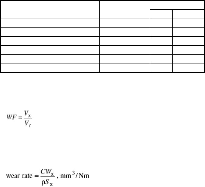
ceramics, metal matrix composites, etc.) can be compared (Table 2). Typically, the reference material is an
alloy that is easily obtainable so that it can be used by anyone with a pin abrasion tester in order to compare
results with those of other researchers. Usually, the heat treated condition of the reference pin is given by a
hardness value (e.g., ASTM A 514/A 514M, type B hardened to HB 269).
Table 2 Typical pin-on-drum wear data for ferrous alloys
Abrasive wear
(a)
Alloy and
designation
Hardness, HB
WF
mm
3
/m
Stainless steel, type 304 207 0.73
0.86
Low-alloy steel, ASTM A 514 256 0.98
1.11
Low-alloy steel, AISI 4340 540 0.73
0.95
Tool steel, type D2 698 0.42
0.49
High-chromium white cast iron
661 0.27
0.31
Carbon steel, AISI 1060 785 0.50 0.56
Note: Load, 66.7 N (15 lbf); pin diameter, 6.35 mm (0.25 in.).
(a) WF, relative wear factor
If a reference material is used in the pin abrasion test, a ratio of the volume loss of the specimen of interest and
the reference pin can be calculated from the following relationship:
(Eq 3)
where WF is the relative wear factor for a given set of abrasive test conditions (i.e., load, sliding distance, and
abrasive), and these conditions should always be stated. The term V
x
is the volume of material lost to abrasion
for the test specimen under the given test conditions, while V
r
is the volume lost to abrasion for the reference
specimen. In ASTM G 132, the normalized wear is calculated in the following manner (Ref 27):
(Eq 4)
where W
x
is the mass loss of the specimen (in any units), S
x
is the mass loss of the reference specimen (in the
same units as W
x
), ρ is the density of the test specimen (known or measured to three significant figures) in
g/cm
3
or mg/mm
3
, and C is the reference constant equal to the mean mass loss (also in grams or milligrams) of
the references pin per unit track length (in meters) per unit load (in newtons) for the abrasive type and test
parameters used. The ratio C:S
x
functions as a normalizing factor. (The value of C should be determined for
each abrasive particle type and size used in a pin abrasion test. Using many rolls of abrasive over a number of
years can cause large errors in the determination of C.)
As an alternative method for determining wear rate from the mass loss data, one of the many equations listed in
the literature can be used (Ref 30). Typically, these equations represent the wear as either the specific wear rate
(mm
3
/Nm), a dimensionless wear coefficient, or as the volume wear (mm
3
/m). Wear rate can also be
represented as the total volume of material lost (mm
3
) for a specific set of test conditions (i.e., abrasive size,
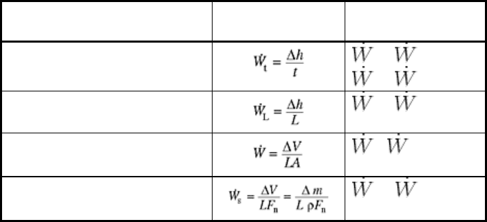
abrasive type, applied load, and sliding distance). Table 3 lists some of the ways in which wear rate can be
represented.
Table 3 General definitions of wear rate
Definition Equation
Relationships
between wear rates
Time-dependent wear rate
t
=
s
pν
t
= ν
Distance-dependent wear rate
t
=
L
p
2
ν
Dimensionless wear rate
=
L
p
2
Specific wear rate
s
=
L
p
Note: Δh, height loss of specimen; t, time of operation; L, sliding distance; ΔV, volume loss; A, apparent contact
area; F
n
, normal load on specimen; Δm, specimen mass loss; ρ, density of specimen; p, pressure; ν, velocity.
Source: Ref 30
Variation in test results for the pin-on-drum abrasion test at a single facility is consistently less than 5% for
homogeneous metals, alloys, and ceramics, and in some cases, less than 1%. For composite materials and
composite-type materials such as high-chromium white cast irons, the variance is typically between 5 and 10%,
depending on the reinforcement and the strength of the interfacial bond between matrix and reinforcement (Ref
31, 32, 33).
In addition to ranking materials, the pin-on-drum abrasive wear test is very effective in discerning volume wear
and wear mechanisms for a wide range of metals, alloys, composites, ceramics, and polymers. The surface area
remains constant during the test, and consequently, different materials can be compared directly for volume loss
and material-removal mechanisms.
Dry Abrasion against Loose Particles
Many cases of abrasive wear occur where the abrasive particles are not fixed but are free to slide and rotate.
The dry sand, rubber wheel (DSRW) abrasion test apparatus simulates one such environment (i.e., low-stress,
three-body abrasive wear) (Ref 34, 35). This type of wear occurs in the mining industry in linkages, pivot pins,
and wire ropes, which suffer slow wear from the sliding and rolling action of abrasive fragments of rock and
ore trapped between metal surfaces. It also occurs in agricultural tillage tools. Since this type of wear is slow,
field trials alone are much too long to be effective in evaluating new materials. The DSRW abrasion test
presents researchers with a quick and easy way to perform numerous tests, rank materials, and correlate the
result with selected field tests. Even before the test became an ASTM standard (G65) in 1980, it had been used
by a number of laboratories for many year. Since becoming an ASTM standard, it has become one of the most
popular abrasive wear tests in the United States for ranking materials. As such, many companies have
developed a qualitative understanding of how their materials perform in a particular wear environment relative
to other materials.
DSRW Equipment and Specimen. The basic ASTM machine (Fig. 4) consists of a chlorobutyl rubber-rimmed
steel wheel, 228 mm (9 in.) diam × 12.7 mm (0.5 in.) wide; a sand hopper connected by a tube to a nozzle that
allows 300 to 400 g/min sand flow; a revolution counter that stops the drive motor after a set number of
revolutions; and a weighted lever arm that holds the specimen and produces a horizontal force against the wheel
where the sand is flowing. The sand is 50/70 mesh Ottawa sand (although other rounded quartz sands may be
used). The mesh size corresponds to a particle size range of 212 to 300 μm. The hardness of the chlorobutyl
rubber on the wheel must be durometer A - 60 ± 2.
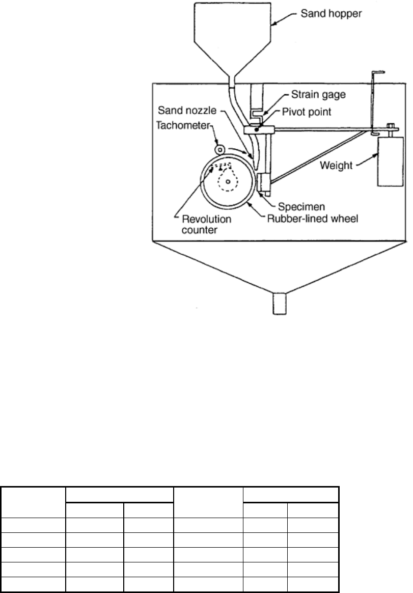
Fig. 4 Schematic diagram of the dry sand, rubber wheel wear apparatus. Source: Ref 35
A typical test specimen is a rectangle, 25 mm (1 in.) wide × 75 mm (3 in.) long, that is 3 to 13 mm (0.1 to 0.5
in.) thick. The wear surface is ground flat with a surface finish of at least 0.8 μm. The density of the test
material must be known in order to calculate the volume of material lost during the course of the test.
DSRW Test Procedure. The equipment has two test parameters: the sliding distance (i.e., the number of wheel
revolutions) and the specimen load. ASTM recognizes five procedures using variations of these two test
parameters (Table 4).
Table 4 Standard conditions for the dry sand, rubber wheel abrasion test
Force on specimen
Distance abraded
ASTM
procedure
N lbf
Wheel
revolutions
m
ft
A 130 29 6,000 4,309
14,137
B 130 29 2,000 1,436
4,711
C 130 29 100 71.8
235.6
D 45 10 6,000 4,309
14,137
E 130 29 1,000 718 2,356
A test consists of the following eight steps:
1. Cleaning and weighing the specimen
2. Mounting the specimen in the lever arm fixture and loading the lever arm fixture
3. Starting the sand flow through the nozzle
4. Starting the rubber-wheel drive motor
5. Releasing the lever arm so that the specimen contacts the wheel, starting the revolution counter
6. Stopping the motor (automatic) and sand flow
7. Removing the test specimen
8. Cleaning and reweighing the test specimen to determine the mass loss during the course of the test.

From the mass loss and the density of the material, the volume loss is calculated. The test is repeated one or
more times. The coefficient of variation between two or more tests for a material must not exceed 7% in order
to meet ASTM specifications for a valid test. Wear-scar nonuniformity is another reason for invalidating test
results. A nonuniform wear scar is an indication that the sample lever arm was misaligned or that the
chlorobutyl rubber wheel has deteriorated and must be redressed.
Two points need to kept in mind when performing DSRW tests. First, moisture in the sand may affect the flow
rate of the sand through the nozzle (agglomeration of sand particles) and thus affect test results. In order to
prevent this from occurring, it is good practice to dry the sand prior to use in some sort of oven at
approximately 100 °C (210 °F), typically for more than 1 h. However, before using the sand in a test, it must be
allowed to cool to room temperature. Reproducibility will also be improved if the sand is sieved prior to its use
in the DSRW to remove foreign debris that may have inadvertently been included when the sand was bagged.
Using a 40 mesh (425 μm) sieve will allow the sand to pass through while trapping agglomerations and other
debris. A second factor that may adversely affect the results is softening of the chlorobutyl rubber wheel. After
any test, the friction between the rubber wheel, sand, and specimen causes the rubber to heat up and soften.
Consequently, the rubber must be allowed to cool to room temperature before another test is run. Typically, 1 h
between tests is sufficient.
For most ferrous materials, testing is performed using a 130 N (29 lbf) load for 2000 revolutions of the rubber
wheel (ASTM procedure B in Table 4), leading to volume losses ranging from 20 to 120 mm
3
. The
reproducibility of the test is highest for volume losses in the range of 20 to 100 mm
3
.
Typically, in tests in which less than 20 mm
3
is lost, any small material inhomogeneities are greatly magnified;
therefore, a more severe test should be run by using either a greater sliding distance or higher load. Above 100
mm
3
of material loss, the wear groove becomes so deep that it may contact the edge of the rubber wheel and
cause erratic results. Therefore, a less severe procedure may be necessary. Using another procedure has a
disadvantage in that test results cannot be directly compared among different procedures.
The DSRW test should be used only for the ranking of various materials, not for determining the absolute
values of wear. For example, a material that wears half as much as another in this test probably will not last
twice as long in the field because the test tends to exaggerate differences. Field factors such as the hardness and
particle size of the abrading material will affect the absolute values of wear more than they affect the ranking.
Typical wear data are presented in Table 5. In general, there is reasonable correlation between hardness and
wear, with the amount of material removed decreasing as the hardness of the material increases.
Table 5 Typical dry sand, rubber wheel abrasive wear data
Volume loss, mm
3
Alloy Hardness, HV
Procedure A
Procedure B
Stainless steel, type 304 207 408.0
170.8
Low-alloy steel, ASTM A 514 256 …
134.1
Low-alloy steel, AISI 4340 540 …
74.0
Tool steel, type D2 689 45.3
14.6
High-chromium white cast iron
661 31.5
12.7
Carbon steel, AISI 1060 785 … 32.1
One criticism of the DSRW test is that the area of contact changes as the test proceeds. That is, as the volume of
material removed by abrasion increases, the surface area of contact between the rubber wheel and the DSRW
sample increases. Thus, the effective contact area increases continually during the course of the test. This
circumstance makes direct comparison of material loss between specimens impracticable, especially for those
situations where material volume loss is greater than 20 mm
3
.
An advantage of DSRW testing over pin abrasion testing is that different types of abrasive particles can be
used. Of course, doing this moves the test away from the ASTM standard 50/70 mesh Ottawa sand, but more
realistic information can be obtained concerning the wear that occurs to a material as a result of a particular
abrasive. The process of creating sand for use in the DSRW is straightforward. The ore of interest must be
crushed, sized, washed, and dried. The sand should then be tested to determine whether the flow rate falls
within the ASTM specifications (i.e., 300–400 g/min). If not, another nozzle should be fabricated that provides
this flow rate. The wear test is then run as per the procedures specified in Table 4.
DSRW Test Variants. In order to obtain more information about the three-body abrasive wear process and to
exert more control over test parameters, modifications to the standard DSRW test have been made (Ref 36, 37).
Aside from a change in the position of the wear specimen (where it is placed in a horizontal configuration
instead of the vertical one specified in G 65), major differences in operation include better control of particle
feed rate (and the use of less abrasive during the course of the test), the ability to change wheel material (metal,
polyurethane rimmed in addition to the usual rubber rimmed), the measurement of tangential traction forces
(leading to calculation of the coefficient of friction), shorter duration tests, and the ability to use different
abrasives. These configurations permit the load per particle and the packing density of the abrasive within the
contact region to be determined. Research has shown that the steady state wear rate is reached at approximately
200 wheel revolutions, so tests of shorter duration can be run, with multiple tests run on the same specimen.
Wet Abrasion against Fixed or Loose Particles
Two significantly different test approaches have been developed to perform wet abrasive wear tests. One
approach, similar to the DSRW, is defined in ASTM G 105, “Standard Test Method for Conducting Wet
Sand/Rubber Wheel Abrasion Tests” (Ref 38). The other wet abrasion tests use the principles associated with
the grinding, polishing, and lapping of materials (Ref 39). The former test can be roughly classified as a
macroabrasion wear test, while the latter one is more of a microabrasion wear test.
Wet Sand/Rubber Wheel Abrasion Test. The wet sand, rubber wheel (WSRW) test is almost identical to the
DSRW test. In this test (i.e., ASTM G 105) (Ref 38), a test specimen is abraded in a slurry containing abrasive
grit of controlled size and composition. As in the DSRW test, the abrasive is introduced between the test
specimen and a rotating neoprene rubber-rimmed wheel of specified hardness. Unlike the DSRW test, however,
where the abrasive is directed between the specimen and the rubber-rimmed wheel using a gravity feed system,
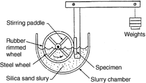
the wheel and specimen in the WSRW test sit in the slurry with stirring paddles agitating the mixture of sand
and water. This constant agitation facilitates the movement of abrasive particles to the specimen rubber-rimmed
wheel interface where they are caught and used to abrade the specimen in the direction of wheel rotation.
Figure 5 is a schematic diagram of the WSRW apparatus. The test apparatus consists of the following major
parts: rubber-rimmed wheel with stirring paddles, slurry chamber, and specimen holder and loading assembly.
The rubber-rimmed wheel and paddle assembly is nominally 178 mm (7 in.) in diameter (including the rubber
rim) by 13 mm (0.5 in.) in width. Neoprene GW is used as the elastomer for the rubber rim with other
constituents added to give the desired durometer A hardness (Ref 38). The slurry chamber must be large enough
to hold the 0.940 kg of deionized water-1.5 kg rounded grain quartz sand (AFS 50/70) slurry. The slurry is
typically only used once and then discarded because multiple use of the sand-water slurry may affect test
comparisons.
Fig. 5 Schematic diagram of wet sand, rubber wheel wear apparatus. Source: Ref 38
For the DSRW test, only one rubber-rimmed wheel of specified hardness (Shore A durometer 60 ± 2) is used.
In the case of the WSRW test, three rubber-rimmed wheels of different hardnesses (Shore A durometer 50, 60,
and 70, all of ±2 variance) are used to determine the wear rate. The WSRW test procedure is very
straightforward. First, the test specimen (nominal dimensions: 57 mm, or 2.2 in., long × 25 mm, or 1 in., wide ×
6.5 - 16 mm, or 0.26 - 0.63 in., thick) is placed in the specimen holder and immersed in the sand-water slurry. It
is then loaded with a mass equivalent of 222 N (50 lbf) force and run in for 1000 revolutions of the wheel (total
sliding distance of 558.6 m, or 1833 ft). The run-in eliminates the machined surface layer and exposes fresh
material that has not been affected by the surface preparation procedure. The test specimen is then removed,
thoroughly cleaned, dried, and weighed (to the nearest 0.0001 g). The slurry chamber is the drained and rinsed
to remove any remnants of sand-water slurry from the run-in step.
The actual test begins at this point and is conducted in the run-in wear scar using either the same durometer 50
wheel used in the run-in or with another durometer 50 rubber-rimmed wheel. (Before each test is run, the
durometer A hardness must be measured for the rubber-rimmed wheel at several points around the periphery.)
The actual test follows the same procedure used to perform the run-in; that is, a 222 N (50 lbf) force is used to
press the test specimen into the wheel in the presence of fresh sand-water slurry for an additional 1000
revolutions of the wheel. After the test, the sample is removed, cleaned, and weighed. The slurry is discarded
and the chamber is rinsed out. Additional 1000 revolution tests are then performed using the durometer 60 and
70 wheels (in increasing order of hardness). From each of these tests, the normalized mass loss is calculated.
The normalized mass loss for each durometer A hardness is then graphed on semilog coordinates as a function
of the wheel hardness. The mass loss is plotted on the log scale while the wheel hardness is plotted on the linear
scale. The reportable mass loss is obtained by fitting a least square line to the three data points and solving the
equation for a hardness value of exactly durometer 60. The durometer 60 normalized mass loss can be
converted to a volume loss by dividing by the density of the test material.
As with any wear test apparatus, the WSRW unit should be periodically checked to make sure it continues to
operate within normal conditions. As with all ASTM tests, a reference specimen is used to establish and
periodically verify machine variance. For a specific reference material, a minimum of five tests should be run to
establish the machine operating parameters and precision. Subsequently, additional tests can be run with the
reference specimens and these results compared against the baseline operating parameters. If the variation is
greater than 7%, the machine should be considered out of control and steps taken to bring it back into
compliance.
One advantage of the WSRW test is that variations in the hardness of the rubber-rimmed wheel, which plague
the DSRW test, are lessened. For example, it has been observed that a difference in the durometer A hardness
of 3 points produces a variation of 30% in the total mass loss (Ref 40). By using wheels of three different
hardnesses, and normalizing the mass loss to the durometer 60 value on the least square line, more consistent
values of wear rate are obtained. The linear nature of the lines on the semilog plot supports this approach. In
addition to rubber-wheel hardness variations, the following variables also affect the reproducibility of the wear
data: “loss of diameter” of the rubber wheel (accounted for by normalized mass loss calculations) (Ref 38),
rubber wheel surface finish (a freshly dressed wheel holds abrasive grains better than a glazed wheel (Ref 40),
rpm of the rubber wheel, specimen surface finish, pressure, slurry density, and slurry temperature. All of these
variables, except slurry temperature, are addressed specifically in ASTM G 105.
For very wear-resistant materials, the number of wheel revolutions may need to be increased in order to obtain
mass loss with the required statistical accuracy. If this is done, the procedure used is the same as just outlined.
Other abrasive-type slurry mixtures can be used in this test as needed to simulate applications. However, doing
this makes the test nonstandard, and all operating parameters should be carefully controlled and noted so
comparisons can be appropriately made. This wear test is not as widely used as the DSRW test because of the
time and effort required to produce a valid result.
Metallographic Polishing Microabrasion Wear Tests. In order to determine the wear rate of a material, a
metallographic polishing wheel can be used as the abrasive application device, where the sample can be
abraded against alumina or silicon carbide paper, or against a diamond polishing disk, using water as a fluid
lubricant for two-body abrasive wear conditions, and against a metal lapping wheel using a slurry of some
composition for three-body abrasive wear conditions. The wear sample may be rigidly fixed relative to the
wheel and abrasive (i.e., moving in the same wear track with the wear rate decreasing as a function of sliding
distance, a result of the interstices between the abrasive particles becoming clogged with wear debris). Or, the
sample may undergo a complicated movement relative to the wheel and abrasive (as in the case of an automatic
polisher where the head rotates the samples so that they encounter fresh abrasive and so that the wear debris can
be flushed from between the abrasive particles). A third type of wear tester that makes use of a modified pin-
on-disk sliding wear tester and resin bonded grinding disks has been developed. The wet abrasion tests in this
section are nonstandard, but they offer different ways to perform abrasion testing on materials.
In using metallographic grinding, polishing, or lapping equipment as the wear test apparatus, care must be taken
to identify and monitor all operating conditions used, such as wheel velocity, sample holder velocity (if
necessary), applied load, test duration, abrasive delivery system (i.e., abrasive size, particle loading, liquid
suspension, delivery rate), sample dimensions and configuration, and wear loss determination method. One
technique, the Struers Micro Wear Test (Ref 39, 41), has standardized these operating features using the Struers
Abrapol-2. In this test, three identical samples are abraded during one wear-test cycle.
Sample preparation is critical to the success of this test because a modified metallographic sample holder is
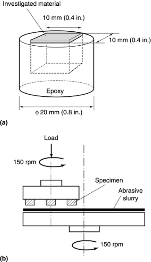
used to hold the wear specimens. Typically, the wear samples are cut into cubes (e.g., 10 × 10 × 10 mm
3
) and
embedded into epoxy resin under controlled conditions using a special mounting device (Fig. 6a). In this way, a
small thickness (~1 mm) of material protrudes from the mount so that abrasion occurs only to the specimen
material and not the mounting resin. The samples are then lapped to a mirror finish using 3 μm diamonds (i.e.,
to make sure all samples start with a uniform and planar surface). They are then thoroughly cleaned, dried, and
weighed before being mounted into the specimen holder. The specimens are separated from each other by 120°
in the holder.
Fig. 6 Schematic diagram of (a) sample and (b) wear apparatus used for performing microabrasion wear
tests. Source: Ref 41
The sample holder with specimens is then inserted in the polishing unit. As with most automatic metallographic
polishing units, the sample holder is rotated at high speed (in this case, 150 rpm) relative to the rotating 300 mm
(12 in.) diameter disk (Fig. 6b). In this way, the samples do not follow the same wear path on the disk but
sweep the whole working area, thus encountering fresh abrasive as determined by the slurry handling system
throughout the test. A cast iron disk (210 HV) is used with the slurry, and off-center concentric grooves are
machined into its surface to hold slurry and wear debris. The load on the wear samples can be varied, from
between 20 and 1200 N (4.5 and 270 lbf), depending on the sample cross-sectional area. Disk and specimen
holder velocity is also variable, yielding specimen velocities of between 1.0 and 7.5 m/s. Test duration is
