ASM Metals HandBook Vol. 8 - Mechanical Testing and Evaluation
Подождите немного. Документ загружается.

Testing Methods for Solid Friction
K.G. Budinski, Eastman Kodak Company; P.J. Blau, Oak Ridge National Laboratory
Friction Measurements
A number of precautions must be observed during friction measurements, and most have to do with the
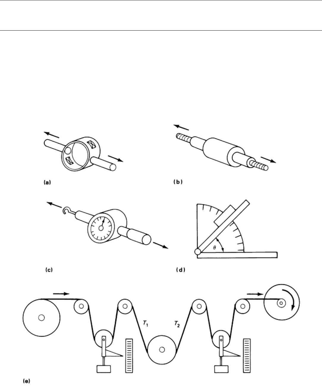
measuring equipment. Some of the more commonly used force-measuring systems are illustrated in Fig. 13.
Probably the most important consideration with regard to instruments for measuring friction forces is selection
of a force-measuring system that is suitably sized for the task. If the tribosystem being tested will produce
friction forces of about 4.5 N (1 lbf), it is recommended that a force-measuring system with a capacity of only
about 45 N (10 lbf) be used. In other words, a sensor with a capacity not more than 10 times the force to be
measured should generally be selected for a given application.
Fig. 13 Friction force sensors. (a) Strain ring with strain gages. (b) Strain gage load cell. (c) Mechanical
force gage. (d) Inclined plane. (e) Web tension tester (tension is measured by the position of the weighted
sheaves)
The strain ring illustrated in Fig. 13(a) is assembled in the laboratory and features four strain gages adhesively
bonded to the ring to form a Wheatstone bridge strain rosette. This type of system can be very accurate, because

the ring can be made as heavy or as light as desired. The disadvantages are that such gages are more fragile than
purchased gages, and humidity and temperature can affect the adhesion of the gages. This system also requires
assembly by a person with some expertise in strain gages.
The commercially available strain-gage load cells shown in Fig. 13(b) are quite durable. Most have some type
of internal diaphragm that is instrumented with strain gages. However, these devices can be destroyed by a
momentary load greater than its capacity, necessitating expensive replacement. Many companies offer these
gages with mechanical stops to prevent overload damage.
Mechanical force gages (Fig. 13c) work much like strain gages, except that force measurements are made by a
spring and sliding system arrangement. The greatest disadvantage of such devices is that they have no recording
capability. They are also prone to inaccurate readings by operators.
Friction coefficients measured on inclined planes (Fig. 13d) require only the measurement of the angle at which
motion of the test block occurs. The most common technique for measuring this angle is the simple
incorporation of a protractor scale in the device. A more accurate system uses an electronic level on the inclined
plane. These devices have digital readout capability and are much more accurate than visual assessment of the
angle of an inclined plane. One precaution in using this type of device is that the speed at which the plane is
raised will affect the breakaway angle. The more reliable inclined plane rigs have a motorized raising device on
the table.
The device illustrated in Fig. 13(e) is commonly used to measure the friction coefficient of a moving web over
a stationary surface or over a roll where relative slip is occurring. The tension in the web on either side of the
test roll will yield the coefficient of kinetic friction when the capstan formula is used. The tension-measuring
roll, called a “dancer roll,” moves up and down with changes in web tension. The disadvantage of these systems
is that they are not very easy to gage electronically, and, thus, continuous recording can be difficult. Most
dancer rolls are being replaced by cantilever rolls with strain gages incorporated in their mounting brackets.
Whichever force-measuring technique is used, it is most important that the device be sized correctly and that
friction forces be recorded over a sufficient period of time to ensure that steady-state conditions exist.
Computerized data acquisition systems may be used for high-speed digital recording if the details of frictional
behavior are needed. The digital data can be used to rapidly calculate average friction force, standard deviation,
and other statistical parameters. Sometimes, however, high-speed friction recordings can produce hash in the
signal, and a filtering algorithm must be used to reveal the general trends. The response of common chart
recorders is usually slow enough to eliminate the hash problem, and, therefore, such chart recorders are still
useful for recording trends in the overall friction behavior.
The final precaution that warrants consideration is the system stiffness. If a system is prone to stick-slip
behavior or high static friction, a highly compliant force-measuring system should be used. From a practical
standpoint, an elastic force-measuring system usually consists of nylon fishing line to pull member A along
member B. If a stiff-movement system such as a screw drive is used to produce specimen motion, phenomena
such as stick-slip behavior might not be produced. The decision as to whether a high-stiffness (steel) or low-
stiffness (plastic) system should be used must be based on the intended application. If the tribosystem of
interest is highly elastic, the plastic-movement system should be used. If the system is rigid, the screw-drive
system (or a similar system) should be used.
Testing Methods for Solid Friction
K.G. Budinski, Eastman Kodak Company; P.J. Blau, Oak Ridge National Laboratory
Overall System Considerations
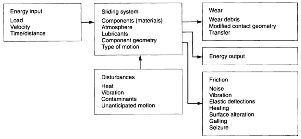
A proposed method for analyzing wear problems is to look at the tribosystem and tabulate all of the system
inputs, outputs, and disturbances (Fig. 14). Friction is considered to be a system loss, but certain components of
friction should be noted and recorded. From the aspect of system usability, sometimes these system losses are
more important than the friction force. For example, in a study on the wear of various cemented carbide
couples, it was learned that some carbide couples produced squealing. The friction coefficient was slightly
higher than comparable metal-to-metal couples (about 0.5 compared with 0.4) while the wear was very low, but
this couple was deemed unacceptable for use because of the noise.
Fig. 14 Systems approach for analyzing friction and wear problems
In Fig. 14, important losses include vibration, elastic deflections, heating, surface alteration, galling, and even
seizure. Vibration as an output of a sliding system often indicates that stick-slip behavior is prevalent. Noise is
often the result of stick-slip behavior, but a system that exhibits such behavior does not necessarily emanate
noise. Although vibration is not always apparent on friction force traces, it can show up on deflection or
displacement transducers. This type of behavior from a sliding system is usually undesirable. Accurate
measurement of vibration can require the use of accelerometers on one of the members of the sliding system.
Likewise, elastic deflection, which can occur at a sliding interface, does not always show up on the friction
force recording. This deflection can mean that the couple under study has unacceptable frictional
characteristics. For example, when several elastomers that were undergoing friction tests were slid on a paper
counterface, they bent over in the direction of motion; the contact geometry was changed from the point contact
of a hemispherical rider to a line contact of a bent hemispherical-ended rod. The friction force was apparently
high enough to cause this deflection.
Although heating is an obvious result of friction between sliding members, it is often not measured. The
temperature rise is often significant, and it is easy to measure. The mechanical properties of plastics are
susceptible to degradation by heating to relatively low temperatures. The temperature rise at a sliding interface
is the result of the properties of the materials in contact in addition to the sliding conditions. It will be different
for different couples that can have the same friction coefficient. Therefore, for sliding systems that can be
affected by frictional heating of the interfaces, a valid friction test should record the temperature rise.
Surface alteration is another important aspect of many wear and friction tests. Whenever wear occurs in a
sliding test, the friction coefficient is not that of the test couple alone, but it is the system that comprises the
couple as well as wear debris in the interface. When wear testing couples that are not supposed to wear during
friction testing, it is important to examine both surfaces for alterations. Damage often can be caused by
polishing or scratching. When friction alters the prevailing surface texture, a wear test has been performed, not
a friction test. The friction force measured and coefficient of friction must be reported for a worn surface.
Galling and seizing are the worst possible results of a friction test. Galling is characterized by the formation of
microscopic cumulative material transfer during sliding, and seizure (stopping of motion) can be the net result.
If a couple seizes, there will be no friction coefficient to report, but merely the fact that the couple seized. If
galling occurs, the friction force will often decrease (Fig. 15), but the surfaces will be damaged. This can
produce data that misleads a user, who may think that the couple works fairly well because the friction
coefficient was low, when actually galling occurred and the material couple is not compatible.
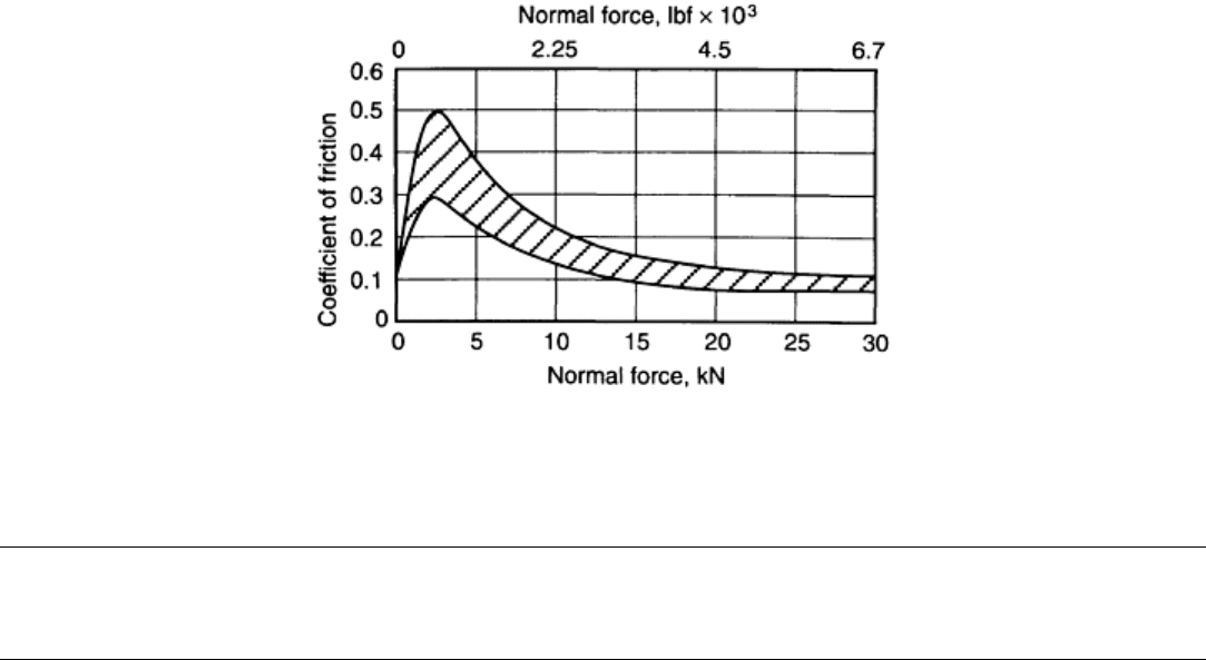
Fig. 15 Typical friction coefficients derived from galling tests (various metal/metal couples)
Testing Methods for Solid Friction
K.G. Budinski, Eastman Kodak Company; P.J. Blau, Oak Ridge National Laboratory
Friction Databases
The first friction database was complied by J.T. Desagulies around 1725 (as reported by Dowson in Ref 1).
Desagulies tabulated the friction coefficients for the couples of interest at the time. Some current handbooks list
friction coefficients for 50 or so materials, with limited documentation regarding test conditions. These
tabulations are of little use if the application requires knowing a friction coefficient within an accuracy of ±0.2.
Differences in the tribosystem used to make the measurements can, for example, produce a result of 0.1 for a
couple on device No. 1 and a result of 0.3 for the same couple tested on device No. 2. It can be stated with a
high degree of confidence that measuring techniques will have a significant effect on the friction coefficient of
a particular couple in the unlubricated condition. Differences can exist in lubricated systems, but the
coefficients will be much lower. An accuracy of ±20% results in a much smaller number. For example, well-
lubricated steel couples can have a kinetic coefficient of friction of 0.05 (±20% makes the number 0.04 to 0.06).
In other words, existing friction databases have limited utility unless the test conditions used to develop the data
are stated and the application conditions are similar.
In order to determine how friction databases should be formulated and used, ASTM Committee G-2 on wear
and erosion developed a standard format for frictio
n databases in 1987. Although this work is ongoing, progress has been made as to the type of data that should
go into databases. The minimum results to be reported are the following:
• Test couple (member 1 and member 2)
• Static coefficient of friction
• Kinetic coefficient of friction
The minimum test condition information includes the following:
• Apparent pressure
• Normal force
• Velocity
• Temperatures (bulk) of samples
• Test atmosphere
• Lubricant

• Sliding distance (when μ was measured)
Other types of data would also be desirable, but even the ASTM-recommended list is difficult to deal with in
database or spreadsheet types of software. The strategy is to have these data in a database so that selective data
can be tabulated (see Table 3). The motivation for establishing friction databases is the elimination of repetitive
tests. Even within a single laboratory, it is not uncommon to see the same couples brought in for study several
times over a period of several years. Without a database, the tests are rerun each time. The long-range goal is to
have published data that can be used by design engineers in the same way that designers use corrosion data
generated by countless sources over many years.
Table 3 Friction and wear data of selected plastics tested against polycarbonate containing 12%
polytetrafluoroethylene
Plastic
(a)
Kinetic coefficient
of friction, μ
k
Specific wear rate
of selected plastic
(b)
,
K × 10
-6
PC 0.19
7.00
PC + PET 0.19
7.26
PCTG + 30% GF 0.36
9.00
PET + 30% GF 0.27
9.00
PET + 30% GF + mica 0.29
8.00
PC + 10% aramid 0.09
4.00
PA + 10% aramid 0.08
0.80
PA + 15% aramid + 10% TFE
0.70
0.50
LCP wear grade 0.10
2.00
LCP + mineral 0.07
0.60
PC + 40% aramid 0.18
9.00
PC/IPN + 2% aramid 0.15
2.00
PC + 20% aramid 0.20 7.00
(a) PC, polycarbonate; PET, polyethelyene terephthalene; GF, glass fiber, PA, polyamide; LCP, liquid crystal
polymer; IPN, interpenetrating networks; TPE, tetrafluoroethylene.
(b) Parameters; friction force, F, 9.86 N (2.20lbf); velocity, V, 0.208 m/s (0.682 ft/s); sliding distance, D, 732.0
m (2402 ft)
Reference cited in this section
1. D. Dowson, History of Tribology, Longman, 1979
Testing Methods for Solid Friction
K.G. Budinski, Eastman Kodak Company; P.J. Blau, Oak Ridge National Laboratory
References
1. D. Dowson, History of Tribology, Longman, 1979
2. A.Z. Szeri, Tribology: Friction, Lubrication, and Wear, Hemisphere Publishing Corp., 1980, p 2
3. Friction, Lubrication, and Wear Technology, Vol 18, ASM Handbook, ASM International, 1992

4. P.J. Blau, Friction Science and Technology, Marcel Dekker, Inc., 1996
5. E. Rabinowicz, Friction Coefficients of Noble Metals over a Range of Loads, Wear, Vol 159, p 89
6. B. Bhushan, Handbook of Micro/ Nanotribology, 2nd ed., CRC Press, Inc., 1998
7. R. Booser, Ed., CRC Handbook of Lubrication, Vol 1–3, CRC Press, Inc.
8. Y.-R. Jeng, Experimental Study of the Effects of Surface Roughness on Friction, Tribol. Trans., Vol 33
(No. 3), 1980, p 402–410
Scratch Testing
Vispi Homi Bulsara, Cummins Engine Company;Srinivasan Chandrasekar and Thomas N. Farris, Purdue
University
Introduction
TO UNDERSTAND the basis and applications of scratch testing, it is useful first to consider it relative to
indentation hardness testing (described in detail in the Section “Hardness Testing” in this Volume). It is well
established that indentation hardness testing measures the resistance of a material to permanent, plastic
deformation (Ref 1). Indentation hardness has a direct correlation with the yield strength of a solid, and for
most materials the hardness is directly proportional to the yield strength. Thus, indentation hardness may be
said to “measure” the plastic properties of a material. In a typical hardness test, a sharp (e.g., pyramid) or blunt
(sphere) indenter is pressed into the material being tested, and the hardness is estimated as the load divided by
the contact area of the indentation. The indentation hardness test is widely used both in academic laboratories
and in industry as a tool for characterizing mechanical properties of a material and also as a quality control
measure (Ref 2, 3).
In contrast to indentation hardness, scratch hardness is a parameter that is determined by sliding a hard indenter
tip across the surface of the material (Ref 4). The scratch hardness is again obtained as the load over a load-
bearing area, which is representative of the indenter track. Scratch hardness has some correlation with
indentation hardness in that it also measures the response of a material to plastic deformation. Furthermore,
since scratch formation is a form of controlled abrasive wear, it would seem reasonable to use the test as a
means of ranking materials for their resistance to abrasion in service. This must, however, be done with some
caution since the geometry of the indenter tip may be substantially different from that of the asperities present
on a surface. In practice, scratch testing is typically used to determine the scratch hardness of materials,
characterize the mechanisms of deformation and material removal, compare the abrasive wear resistance of
materials, and measure the adhesion strength of coatings. An examination of its application in these areas
indicates that it is used more as a quality control technique, and furthermore the measure obtained is more
qualitative than quantitative.
This article reviews the origins and development of scratch tests, the experimental configurations used in these
tests, and the application of the tests to characterize the mechanical response of materials.
References cited in this section
1. D. Tabor, The Hardness of Metals, Oxford University Press, 1951
2. M.M. Chaudhri and Y. Enomoto, Philos. Mag. A., Special Issues on Indentation Hardness, 1996

3. S. Jayaraman, G.T. Hahn, W.C. Oliver, C.A. Rubin, and P.C. Bastias, Determination of Monotonic
Stress-Strain Curve of Hard Materials from Ultra-Low-Load Indentation Tests, Int. J. Solids Struct., Vol
35 (No. 5–6), 1998, p 365–381
4. S. Jacobsson, M. Olsson, P. Hedenqvist, and O. Vingsbo, Scratch Testing, Friction, Lubrication, and
Wear Technology, Vol 18, ASM Handbook, ASM International, 1992, p 430–437
Scratch Testing
Vispi Homi Bulsara, Cummins Engine Company;Srinivasan Chandrasekar and Thomas N. Farris, Purdue University
Origins of Scratch Testing and the Mohs Scale
Perhaps the earliest attempt to develop a scale of scratch hardness for different materials was made by Reaumur
in 1722 (Ref 5), who measured the hardness of a substance as the point at which it started scratching a bar
whose hardness decreased from one end to the other. A similar method was used by Werner (Ref 5), who
developed the first real scale of hardness, which was further extended by Hauy (Ref 5). In Hauy's scale, there
were four groups of hardness listed in order of their mutual scratchability.
The Austrian mineralogist Mohs is credited with developing the first semiquantitative measure for scratch
hardness in 1822. This measure is expressed on a scale called the Mohs scale. The Mohs scale consists of 10
minerals, arranged in an order such that each mineral will scratch the one on the scale below it, but will not
scratch any mineral that is above it on the scale. In measuring scratch hardness using the Mohs scale, the sharp
corner of a material is rubbed against the flat surface of another, and the flat surface is checked for scratches. A
material higher up on the Mohs scale would scratch all materials with a lower Mohs number. The Mohs
hardness number for the material being tested is given by the number corresponding to the hardest of the 10
reference materials that does not scratch this material.
Since the scratching process and the indentation process are both determined by the plastic properties of the
material, one may expect to find some correlation between Mohs hardness and the indentation hardness for
minerals. Such a correlation does in fact exist, as shown in Fig. 1, which is based on Williams (Ref 6). Some of
the indentation hardness measurements in this figure were made with the standard Vickers indenter, others with
the Knoop indenter. Both of the indenters produce a pyramidal indentation and give roughly the same hardness
values for materials.
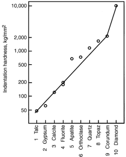
Fig. 1 Variation of indentation hardness with Mohs number. The slope of the line indicates that a unit
change in Mohs number corresponds to a factor of ~1.6 in the indentation hardness. The logarithm of
hardness is plotted in the figure. Source: Ref 6
The gradient of the logarithmic plot of Fig. 1 indicates that each skip in the Mohs scale is equivalent to an
increase in indentation hardness by a factor of ~1.6, with the exception of that between corundum (a form of
aluminum oxide with a Mohs number of 9) and diamond (which has a Mohs number of 10). The uniformity of
this scale in terms of the indentation hardness of the 10 minerals reflects the high quality of the experimental
work of Mohs, who was himself also well aware of the much larger increase on the scale between the Mohs
values of 9 and 10.
The relation between Mohs scale and indentation hardness embodied in Fig. 1 may be interpreted in terms of
the following simple experiment performed by Tabor (Ref 7). By suitable heat treatment, a strip of metal is
rendered soft at one end and hard at the other, with a fairly uniform increase in indentation hardness along its
length. Another metal specimen of uniform intermediate hardness is prepared with a sharp point at one end, and
the point is dragged over the strip from the soft to the hard end. It is found that under well-lubricated
conditions, the friction is high over the soft portion, and a fine chip is produced during sliding. This behavior
changes rather abruptly at a critical value of hardness, where the friction quickly drops to a low value (Fig. 2)
and there is little material removal or surface damage. In terms of Fig. 2 it is seen that a point of Vickers
hardness 930 kg/mm
2
just ceases to scratch the surface when the hardness of the mating surface exceeds about
830 kg/mm
2
. Based on such experiments, it has been generally accepted that for one material to scratch another
the indenter material must be at least 20% harder than the damaged surface. Additional experiments carried out
since this early work have shown that this difference depends on the shape of the indenter, varying between a
few percent harder for a spherical indenter to about 60% harder for a much more angular indenter.
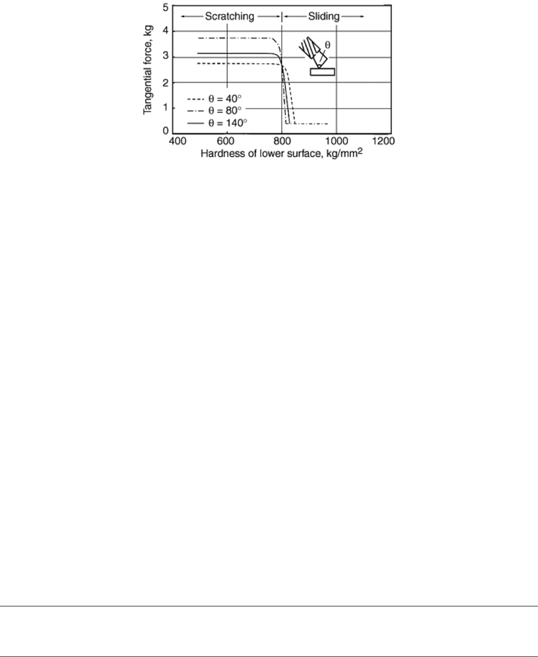
Fig. 2 Frictional force plotted as a function of surface hardness for a metal point of hardness H
p
= 930
kg/mm
2
traversing a steel surface (load 4.2 kg). Lubricated surfaces. Scratching ceases, and the friction
falls to a low value if the hardness of the surface exceeds 830 kg/mm
2
. Source: Ref 7
The apparently linear variation of the logarithm of indentation hardness with Mohs number seen in Fig. 1 can
be easily explained in light of the above results pertaining to scratching. If one assumes that scratching just
begins when H ≥ kH
s
, where H is indentation hardness and H
s
is scratch hardness, then we can construct a
hardness scale in which every unit is k times as hard as the preceding one. The Mohs number (M) is then related
to indentation hardness (H) by a relation of the form:
H = C(k)
M
(Eq 1)
where C is a proportionality constant. Taking the logarithm of both sides of Eq 1 gives:
log H = M log k + Constant
(Eq 2)
Thus a plot of log H against M should give a straight line. From experimental results reported earlier, k has a
value slightly greater than one for a spherical indenter and ~1.6 for a much more angular indenter.
Equation 2 and Fig. 1 can be used to obtain an approximate estimate of indentation hardness of a material when
its Mohs number is specified. Even though Mohs number is not very much used to specify hardness of a
material, it has been the experience of the authors that, not infrequently, they have seen it arise in various
contexts.
References cited in this section
5. S.R. Williams, Hardness and Hardness Measurements, American Society for Metals, 1942
6. J.A. Williams, Analytical Models of Scratch Hardness, Tribol. Int., Vol 29 (No. 8), 1996, p 675–694
7. F.P. Bowden and D. Tabor, The Friction and Lubrication of Solids, Oxford University Press, Vol I,
1951; Vol II, 1964
Scratch Testing
Vispi Homi Bulsara, Cummins Engine Company;Srinivasan Chandrasekar and Thomas N. Farris, Purdue University
Experimental Devices
Scratch tests can be classified into two categories—low speed and high speed—based on the velocity of the
scratching element with respect to the material surface.
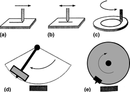
Low-Speed Devices. The scratch element (i.e., indenter) is usually mounted on a linear slide and moved along
the material surface at speeds of no more than a few millimeters per second to generate a single-pass scratch.
The element may be reciprocated against the sample to generate a multipass scratch. Another method used to
generate a multipass scratch is to mount the sample on a rotating turntable and slide it against a stationary
scratch element. These three configurations are shown in Fig. 3(a) to (c).
Fig. 3 Different scratch devices. (a) and (b) Linear. (c) Rotary. (d) Pendulum. (e) Grinding type. Source:
Ref 4
High-Speed Devices. A high-speed, linear slide can be used to provide relative motion of the sample surface
with respect to the scratch element. In this configuration, which is simple and easily instrumented, it is difficult
to achieve speeds greater than about 3 m/s. Single-pass as well as multipass scratches can be generated with this
device. Other high-speed scratching devices utilize a scratch element that is mounted on the end of a pendulum
(Fig. 3d) or on the periphery of a rotating metal disk (Fig. 3e) to generate high speeds, while the sample is
mounted on a slide, which may or may not be moving. Speeds much higher than 3 m/s can be easily achieved
with the rotating-disk device; in fact by mounting the disk on the spindle of high-speed grinding machines it is
feasible to achieve speeds as high as 90 m/s.
In-Situ Scratch Devices. There is a third category of scratching devices that are somewhat less often used.
These may be termed as in situ scratching devices because scratch formation can be directly observed in these
devices, in situ, using an optical or a scanning electron microscope (SEM). The indenter is stationary, and the
sample is slid at a very low velocity by mounting it on a linear slide. In the device, which is mounted inside the
chamber of an SEM, the electron beam is focused at the contact between the scratch element tip and the sample
surface, thereby enabling scratch formation to be observed at high magnification, but at speeds of the order of a
few microns per second. The ambient atmosphere within the chamber may also be varied between a vacuum
(~10
-7
torr) to low pressures of various gases. The authors have developed a simple, in situ device that utilizes
an optical microscope to study scratch formation in optically transparent solids (Fig. 4). A high-magnification
optical microscope with a large working distance objective is mounted behind the sample, enabling observation
of the scratch interface through the sample. The sample is traversed against the scratch element using a high-
pressure linear slide at speed between 25 nm/s and 200 mm/s. A high-speed camera may be attached to the
microscope for high-speed observation. This has made possible a study of scratch mechanisms ranging from
ductile scratching to brittle fracture during scratching of transparent brittle materials like glass, spinel, sapphire,
and several oxide polycrystals, and observation of ductile chip formation during scratching of brittle materials.
Indentation and scratch damage on coatings deposited over transparent substrates can also be studied using this
device.
