ASM Metals HandBook Vol. 8 - Mechanical Testing and Evaluation
Подождите немного. Документ загружается.


7. Standard Test Method for Measurement of Fatigue Crack Growth Rates, E 647-91, Annual Book of
ASTM Standards, Vol 03.01, 1992, ASTM, p 674–701
17. Standard Method for Plane-Strain Fracture Toughness of Metallic Materials, E 399-90, Annual Book of
ASTM Standards, Vol 3.01, 1992, ASTM, p 569–596
18. K.T. Venkateswara Rao, W. Yu, and R.O. Ritchie, Metall. Trans. A, Vol 19 (No. 3), March 1988, p
549–561
19. A.W. Thompson and R.J. Bucci, Metall. Trans., Vol 4, April 1973, p 1173–1175
20. G.R. Yoder and D. Eylon, Metall. Trans. A, Vol 10, Nov 1979, p 1808–1810
Fatigue Crack Growth Testing
Ashok Saxena, Georgia Institute of Technology; Christopher L. Muhlstein, University of California, Berkeley
Crack-Length Measurement
Precise measurements of fatigue crack extension are crucial for the determination of reliable crack growth rates.
ASTM E 647 requires a minimum resolution of 0.1 mm (0.004 in.) in crack-length measurement. Crack
extension measurements are recommended at intervals 10 times the minimum required resolution.
Various crack measurement techniques have been applied, including optical (visual and photographic),
ultrasonic, acoustic emission, electrical (eddy current and resistance), and compliance (displacement and BFS
gages) methods. Optical, compliance, and electric potential difference are the most common laboratory
techniques, and merits and limitations are reviewed in detail in the following sections. Other references are
listed in “Selected References” at the end of this article.
Optical Crack Measurement
Monitoring of fatigue crack length as a function of cycles is most commonly conducted visually by observing
the crack at the specimen surfaces with a traveling low-power microscope at a magnification of 20 to 50×.
Crack-length measurements are made at intervals such that a nearly even distribution of da/dN versus ΔK is
achieved. The minimum amount of extension between readings is commonly about 0.25 mm (0.010 in.).
For planar specimens, the crack length is measured on one or both surfaces, depending on the section thickness.
For example, ASTM E 647 (Ref 7) specifies a B/W value of 0.15 as the limit; measurements on only one side
are sufficient if B/W < 0.15.
Through-thickness variations in crack length must be considered and corrected if too severe. Typical behavior
is for the crack length to lead at the midplane (crack tunneling). Because this situation cannot be observed in
situ by visual monitoring, posttest observations must be made. Rough alignment of the traveling microscope
can be easily achieved by shining a pen light through the eyepiece on the crack-tip region. To ensure accurate
crack measurements, obliquely incident light on a well-polished specimen surface is an effective means of
highlighting fine cracks. High-intensity strobe lights with adjustable function generators are used to allow
“motion free” viewing of cracks during high-frequency tests. The development of extra-long focal length optics
has added new functionality to optical techniques. These microscopes allow the in situ observation and image
analysis of crack-tip processes while keeping the instruments a reasonable distance (>381 mm, or 15 in.) from
the specimen and other testing hardware.
To account for through-thickness crack-length variation, ASTM E 647 recommends measuring the crack length
at five points along the crack front contour and averaging the five readings. If the average of the five points
exceeds the surface length by more than 5%, the average length is used in computing the growth rate and K.
The optical technique is straightforward and, if the specimen is carefully polished and does not oxidize during
the test, produces accurate results. However, the process is time consuming, subjective, and can be automated
only with complicated and expensive video-digitizing equipment. In addition, many FCGR tests are conducted
in simulated-service environments that obscure direct observation of the crack. The trend toward laboratory
automation has resulted in the development of indirect methods of determining crack extension, such as
specimen compliance and electric potential monitoring.
Compliance Method
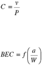
Under linear elastic conditions for a given crack size, the displacement, ν, across the load points or at any other
locations across the crack surfaces is directly proportional to the applied load (P). The compliance, C, of the
specimen is defined:
(Eq 11)
The relationship between dimensionless compliance, BEC, where B is the thickness and E is the elastic
modulus, and the dimensionless crack size, a/W, where W is the specimen width, is unique for a given specimen
geometry (Ref 21). Thus:
(Eq 12)
The inverse relationship (Ref 21) between crack size and compliance can be written as a/W = q(u), where u = [1
+ BEC]
-0.5
. This relationship may be determined numerically using finite element techniques or by experiment.
ASTM E 647 also specifies these relationships for CT and MT specimens.
The compliance of an elastically strained specimen (expressed as the quotient of the displacement, ν, and the
tensile load, P, per Eq 11) is determined by measuring the displacement along, or parallel to, the load line.
Figure 11 illustrates that the more deeply a specimen is cracked, the greater the amount of ν will be measured
for a specific value of tensile load. Additional information on the method and calculation of compliance can be
found in the “Selected References” at the end of this article.
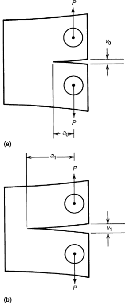
Fig. 11 Schematic of the relationship between compliance and crack length. (a) C(a
0
) = v
0
/P. (b) C(a
1
) =
v
1
/P
Instrumentation. The displacement usually is measured across the crack mouth opening using cantilever beam
clip gages, optical (laser and white light) extensometry, or BFS gages. Linear variable differential transducers
have been used, but hysteresis in the response can sometimes be a problem. Each technique has its own
advantages and may be used to continuously monitor crack length. An additional benefit of compliance
techniques is that the same signal can be used for determining crack closure, as discussed below.
Cantilever beam clip gages, based on resistive and capacitance strain gage technology, are well suited for
elevated (<370 °C) and high-temperature tests (up to 1200 °C), respectively. Deflection of the arms is measured
by the output of the strain gages mounted on the clip gage arms. Extensometer and transducer design theory is
well established in the literature (Ref 17, 22). Attachment of clip gages to the specimen is achieved through
integral, machined knife edges or by knife-edge blocks bolted to the front face of the specimen across the crack
plane.
Optical extensometry techniques include those based on fiber optics and laser technology. There are two main
types of optical extensometry used in compliance measurement. The first type is an advanced laser system that
tracks the motion of spots projected on the specimen. In this instance, the transmitter and receiver are located
on the same side of the specimen. A second group of extensometers measure the width of the notch using a
transmitter and receiver on opposite sides of the specimen. Laser and white light systems based on these
principles are available commercially. Optical systems may have restrictions on frequency response. Like
optical crack-length measurement techniques, most optical extensometry techniques are difficult to use when
testing at elevated temperatures or in environmental chambers.
An electrical resistance strain gage mounted opposite the notch on the back face of the fatigue specimen is
termed a back face strain (BFS) gage. Just as with the clip gage, the load-strain signal from the BFS gage may
be used to determine the crack length in the specimen. While conventional strain gages are limited to elevated
temperatures (<370 °C) in gaseous or aqueous environments, they have the advantage of directly measuring
strain without the application of force. The direct measurement of strain eliminates frequency limitations
associated with clip gages at the expense of having no geometric amplification of the strains or the sensitivity
benefits of a four active leg Wheatstone bridge (Ref 22). A BFS gage is especially useful for nonmetallic
materials where integral knife edges and tapped holes for knife-edge blocks are difficult to machine.
The required sensitivity of the system depends on specimen geometry and sizes. In general, noise-free,
amplified output of about 1 V direct current (dc) per 1 mm (0.04 in.) of deflection is satisfactory. Similarly, for
the load range applied to the specimen, an approximately 1 V dc change in signal from the load cell is required
for accurate calculation of the compliance.
Attachment of Displacement Measurement Hardware. One of the most important factors affecting the accuracy
of crack-opening displacement measurements is the manner in which the displacement transducer is attached to
the test sample. Transducers for measuring the crack-opening displacement commonly consist of cantilevered
arms affixed across the crack. When the crack is opened, deflections either in the arms, or in a flexure attached
to the arms, induces measurable strains, which are ultimately converted to displacements.
To prevent slipping of the gage during testing, the gage must have an adequate, well-documented clamping
force (~2500 g). This force must be added to the mean tensile load applied to the specimen by the gage during
data analysis. For thin or small specimens, the gage-induced mean load may be high enough to preclude testing
at the desired load levels. Even with high clamping forces, there will be a limitation on the maximum testing
frequency for the gage due to the excitation of resonant modes in the gage or inadequate clamping force. If
necessary, higher frequencies can be achieved by bolting the clip gage to the specimen.
The transducer can be bolted across the crack opening at the point of testing, or it can be attached to the
specimen through hardened knife-edge pivots that are mechanically or adhesively affixed to the specimen. The
transducer can also be affixed via knife-edge contacts machined into the test sample. For elevated-temperature
testing, feed-rod systems are frequently used.
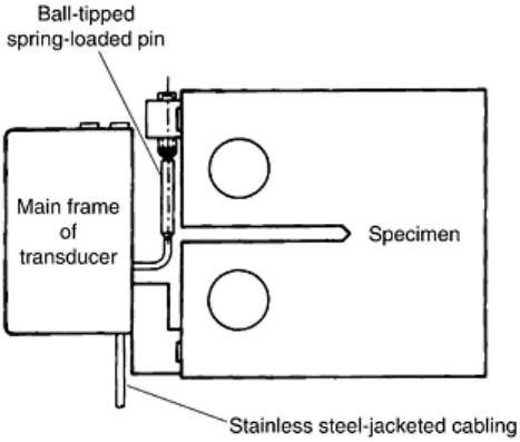
The bolt-on system of attaching the transducer to the test specimen (Fig. 12) is capable of reacting to high
acceleration loads. These loads result from higher-frequency dynamic testing when the rocking movement
generated by the mass of the transducer is carried to the bolt-on attachment through the transducer frame. This
attachment system is preferred when a transducer has high mass or an effective mass center located a great
distance from the specimen contact pads.
Fig. 12 Bolt-on attachment of crack-opening displacement transducer to fatigue test specimen
The bolt-on system also provides accurate crack-opening displacement measurements on specimens tested
under environments not conducive to the use of knife edges, such as elevated-temperature or corrosive
environments. In addition, the bolt-on attachment system allows the use of stiffer cabling without disturbing the
measurement. For example, a displacement transducer with relatively rigid stainless steel-jacketed cabling can
be used to make measurements in pressurized high-temperature water/steam environments.
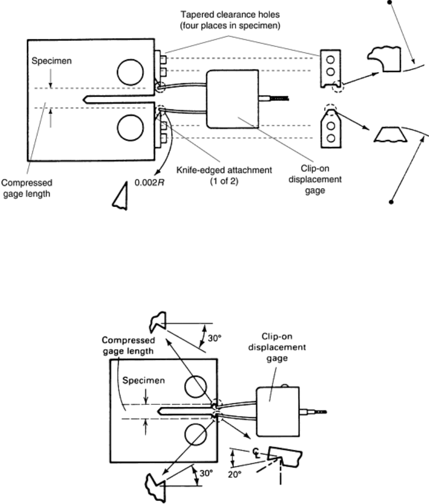
Hardened knife-edge pivot contacts (Fig. 13) provide a measurement system with minimal sliding action; the
knife-edge rocks in a hardened seat in the transducer arm. This condition allows measurements to be made with
very low hysteresis levels. Contact and seat-ramp angles can be designed for optimal tradeoffs between static
and dynamic measurement accuracy, dynamic stability, and contact durability. Male knife-edge contact
replacements are relatively low in cost, and various configurations are available, such as three-point contact,
line contact, large radius, and small radius.
Fig. 13 Bolt-on hardened knife-edge attachment of crack-opening displacement transducer to fatigue test
specimen
Knife-edge contacts machined into the test sample (Fig. 14) eliminate the possibility of knife-edge screws
loosening, resulting in slippage and hysteresis. The compressed initial gage length can be machined to the
required tolerance.
Fig. 14 Attachment of crack-opening displacement transducer to specimen by machined knife-edge
contacts
Computing Normalized Compliance. When measuring the compliance of a fatigue specimen, the usual practice
is to compute a normalized compliance (EBδ/P). This normalized compliance is plotted against a normalized
crack length, a/W. For standard geometries, such as a CT specimen, this relationship has the form shown in Fig.
15. Thus, from the measured compliance, a crack length can be obtained from the known analytical
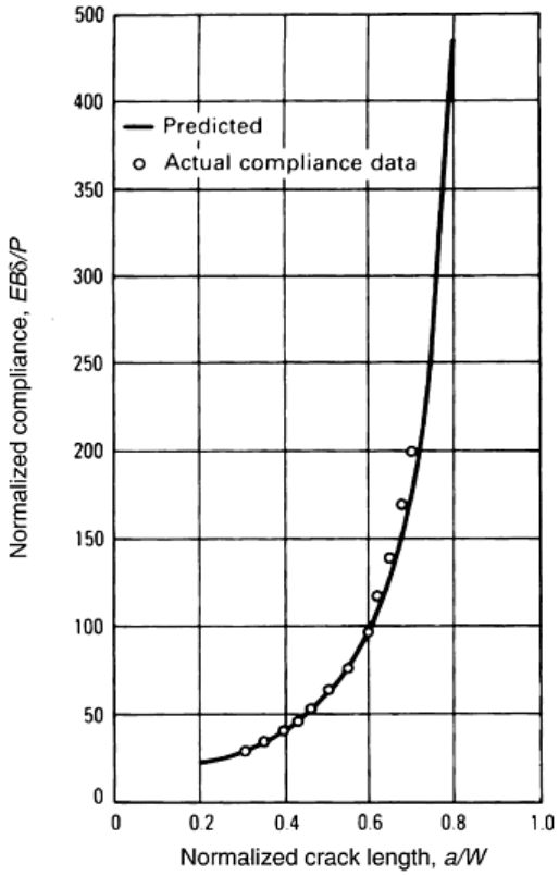
relationships, as shown in Fig. 15 (Ref 21). Note that when the crack is short (a/W ~ 0.2 to 0.4), the compliance
is less sensitive to changes in crack length than when the crack length is long (a/W > 0.5). Thus, the sensitivity
of the compliance method is significantly improved for the longer crack lengths, both because of this
relationship and because the amount of crack mouth opening and the resulting displacement gage signal are
larger. The amount of displacement or measured crack mouth opening is a strong function of the location of the
line of measurement of the gage with respect to the load line, which is the reference point for crack extension.
The farther away from the crack tip the measurement can be made, the more displacement that will be incurred,
and the sensitivity of the method will be improved proportionately.
Fig. 15 Comparison of predicted and experimental compliance for a compact-type fatigue specimen
Data Acquisition and Processing. The signals from the load cell and displacement gage must be obtained
simultaneously in order for this method to work to its best advantage. In the most direct instance, the two
signals can be fed to an x-y recorder, with the load applied to the y-axis and displacement to the x-axis. At
various intervals during the test, a trace of the two signals can be made. If the test is being conducted at a
reasonably high frequency (>1 Hz), then the frequency will have to be reduced so that the slow rate of the
recorder can keep up with the changing voltage. This maintenance is not a problem if a transient recorder is
used and the results from the two channels (load and displacement) are co-plotted. The slopes of the recorder
traces can be measured, multiplied by suitable calibration factors, and used in the compliance to crack-length
relationship.
A more sophisticated method uses a computerized data acquisition system to obtain load displacement data.
These systems are usually faster and, thus, can accept data from rather high-frequency waveforms. In addition,
software can be developed to perform the calculations involved in processing the compliance data to crack
length. Software to perform FCGR measurements is generally available from manufacturers, but most
researchers write their own data acquisition packages, perhaps using some of the manufacturer-supplied
subroutines specific to the hardware involved.
Additionally, data should be taken between about 10 and 90% of the load range. Eliminating the top and bottom
fractions of the load range avoids problems of crack closure (at loads approaching zero) or incipient plasticity
(near the load maximum, at longer crack lengths). The sets of load-displacement pairs are fitted to a straight
line; the slope of which is used in the compliance expression.
Electric Potential Difference Method
The electrical potential, or potential drop, technique has gained increasingly wide acceptance in fracture
research as one of the most accurate and efficient methods for monitoring the initiation and propagation of
cracks. This method relies on a disturbance in the electrical potential field about any discontinuity in a current-
carrying body, and the magnitude of the disturbance depends on the size and shape of the discontinuity.
For the application of crack growth monitoring, the electrical potential method entails passing a constant
current (maintained constant by external means) through a cracked test specimen and measuring the change in
electrical potential across the crack as it propagates. With increasing crack length, the uncracked cross-sectional
area of the test piece decreases, its electrical resistance increases, and the potential difference between two
points spanning the crack rises. By monitoring this potential increase, V
a
, and comparing it with some
referencing potential, V
0
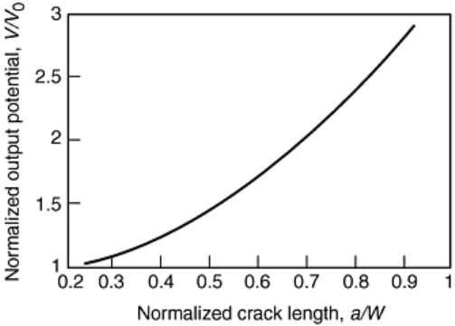
, the ratio of crack length to width, a/W, can be determined through the use of the
relevant calibration curve for the particular test piece geometry concerned. The crack length is expressed as a
function of the normalized potential (V/V
0
) and the initial crack length (a
0
), as shown in Fig. 16.
Fig. 16 Potential response for a compact-type specimen
Accuracy of electrical potential measurements of crack length may be limited by a number of factors, including
the electrical stability and resolution of the potential measurement system, electrical contact between crack
surfaces where the fracture morphology is rough or where significant crack closure effects are present, and
changes in electrical resistivity with plastic deformation. Another key factor is the determination of calibration
curves relating changes in potential across the crack (V
a
) to crack length (a). In most instances, experimental
calibration curves have been obtained by measuring the electrical potential difference across the machined slots
of increasing length in a single test piece; across a growing fatigue crack, where the length of the crack at each
point of measurement is marked on the fracture surface by a single overhead cycle or by a change in mean
stress; across a growing fatigue crack in thin specimens, where the length of the crack is measured by surface
observation.
Other experimental calibrations have been achieved using an electrical analog of the test piece, where the
specimen design is duplicated, usually with increased dimensions for better accuracy, using graphitized analog
paper or thin aluminum foil, and where the crack length can be increased simply by cutting with a razor blade.
Such calibration procedures, however, are relatively inaccurate, particularly at short crack lengths, and are
tedious to perform. Furthermore, where measurements of crack initiation and early growth are required ahead
of short cracks or notches of varying acuity, such procedures demand a new experimental calibration to be
obtained for each notch geometry.
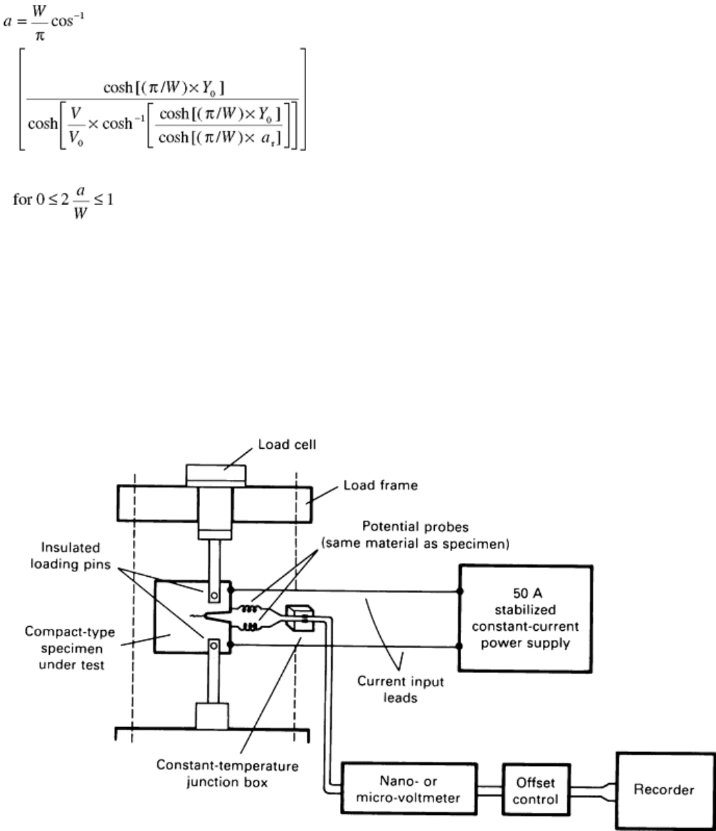
Electric potential response may be determined empirically (Ref 23, 24, and 25) or using numerical methods,
such as finite element or conformal mapping techniques (Ref 26, 27, 28, 29, and 30). Johnson's analytical
solution of the MT geometry is widely used in experimental work due to its flexibility (Ref 28):
(Eq 13)
where a is the crack size, a
r
is the reference crack size from another method, W is the specimen width, Y
0
is the
voltage measurement lead spacing from crack plane, V is the measured electric potential difference, and V
r
is
the measured voltage corresponding to a
r
. With minor modifications, Eq 13 can be applied to edge-cracked
geometries by treating them as half of a MT geometry. Third- or higher-order polynomial expressions with
coefficients obtained from regression analysis can be used to describe the potential response of the specimens
when simplified expressions are required or Eq 13 does not apply.
A schematic diagram of a typical experimental setup for electrical potential crack monitoring measurements is
shown in Fig. 17. The technique can be used with alternating current (ac) or dc power supplies. Alternating
current systems have lower power requirements and do not suffer from the thermally induced potentials that
plague dc systems. On the other hand, dc systems are widely used because of the relative simplicity.
Consequently, this discussion of typical experimental setups is restricted to dc systems.
Fig. 17 Schematic of the direct current electrical potential crack monitoring system
The main component of a dc electric potential system is a power supply capable of producing a large, stabilized
constant current. Applied currents range from 5 to 50 A with output voltages from 0.1 to 50 mV. Power
supplies must be stable to 1 part in 10
4
or better, and nano- or microvoltmeters with a resolution of 0.05 to 0.5
μV are used (Ref 7). It is crucial that all dc potential measurement equipment (power supplies, voltage meters,
etc.) and the loadframe itself be properly grounded. Before a power supply or nearby electromagnetic field

(EMF) source (e.g., induction heater) is faulted for poor performance of the electric potential technique,
researchers are reminded to check that all equipment is properly grounded. In some instances, EMF shielding
may be required.
High-resolution, stable, properly grounded equipment does not guarantee reliable performance and high
resolution for the dc potential difference technique. Proper selection and use of current and potential leads are
essential. High-current (welding) cable is ideal for current input leads, which are usually bolted to the
specimen. To reduce noise, the potential leads should be firmly attached to the specimen, shielded, and twisted
together. To ensure that current will pass through the specimen, the ratio of the loadtrain resistance to that of
the specimen must be on the order of 10
4
. If this ratio cannot be achieved, the specimen must be electrically
isolated using nonconducting (e.g., alumina) pins and washers or sleeves. The current applied to the specimen
should be large enough to produce a measurable potential. Table 1 lists typical current and output voltages for
CT specimens of aluminum, steel, and titanium. Excessive current (>10 A) can cause heating of the specimen
and should be avoided. Potential leads should be made from fine wire of the same material as the specimen to
reduce thermally induced EMF. Potential measurement leads and equipment should be kept away from EMF
sources, such as transformers, to further reduce noise.
Table 1 Typical electric potential difference (EPD) voltages as measured on a standard compact-type
specimen
Material Approximate
EPD, mV
Approximate change
in crack length for 1
μV change in EPD,
μm
Aluminum
0.1
300
Steel 0.6
50
Titanium 3.5 9
Based on a/W = 0.22, B = 7.7 mm, and W = 50 mm. Lead geometry per Ref 7 and direct current of 10 A
Crack tip processes, such as fatigue crack closure (see the section “Crack Closure” in this article), can reduce
the potential of the specimen as the crack faces come together, effectively shortening the crack. This situation is
especially a problem when testing materials that do not form protective, nonconducting oxide layers in the
environment of interest. The solution to this problem is to measure the potential output at the peak load. In
addition to crack closure, crack-tip plasticity and distributed damage, such as microcracking, must be
considered. Large plastic zones, such as those encountered under elastic-plastic conditions, disturb the
equipotential lines much like the crack (Ref 31). Distributed damage processes can also complicate
measurements by making it difficult to define a continuous crack. Hence, optical measurements of the crack
should be made to ensure that the electric potential difference technique provides a realistic representation of
crack length. Changes in the electrical properties of the material can also limit the effectiveness of dc potential
systems.
Changes in conductivity can complicate electric potential measurements. When high-conductivity materials,
such as aluminum, are tested, temperature fluctuations of ±1 °C will cause a change in potential on the order of
a few μV due to the temperature dependence of conductivity, and this change may vary with time. This
condition can limit the crack extension resolution. Environmental chambers are useful with high-conductivity
materials, even when testing at room temperature.
The primary difficulty with the dc electric potential technique is the junction potentials created at points of
current and potential lead attachment. When dissimilar materials are in contact, a potential is generated due to
the thermocouple effect, and it may be of the same order of magnitude as the potential generated by the
specimen. This thermally induced potential, also known as the thermal voltage, may not be constant.
Consequently, care must be taken to separate changes in potential due to fluctuations in thermal voltage from
changes due to crack extension. This concern is especially important when measuring the slow growth rates
found in the near-threshold regime (region I, Fig. 2).
There are three common approaches to account for the thermal voltage. The first method is to periodically turn
off the power supply, note the value of thermal voltage, and subtract it from the output of the specimen with the
current applied. This approach is acceptable for manually run tests, but it is not very useful when a continuous
signal is required for computer-controlled tests. One alternative to manual measurement of the thermal voltage
is to apply a current to an uncracked specimen with no applied load in the same environment as the test
specimen in the “reference potential” technique. The tendency of the thermal voltage to drift should be the same
in both the cracked and uncracked specimens. The drift can then be monitored, and the thermal voltage simply
becomes an offset. Attempts have been made to apply the reference potential technique to a single specimen by
measuring potentials in areas of the specimen that are “insensitive” to crack extension. The development of
high-current-capacity solid-state switches has made the use of fully reversed electric potential drop systems a
third method for dealing with thermal voltages. If the direction of current flow is periodically reversed, the
thermal voltage, which has a fixed polarity, will shift the maximum and minimum output potentials but will not
influence the range or amplitude of the signal. Thus, the amplitude of the output potential can be used to
determine the length of the crack.
The electric potential technique may also be applied to nonconducting specimens with the use of conducting
thin foils. The foils, applied prior to testing, crack with the underlying specimen. Current is applied to the foil
instead of to the specimen, and the calibrated response of the foil may be used to monitor the growth of the
crack. This technique may be used for room- and elevated-temperature tests, provided that the foil accurately
reflects the growth of the crack. Polymer-backed gages sold under the trade name KrakGage (Hartrun Corp., St.
Augustine, FL) require special hardware for mounting and use and may be used with conducting or
nonconducting specimens. It is also possible to vapor deposit gages directly to nonconducting specimens or to
nonconducting oxide films on conducting or nonconducting (e.g., SiC) materials. The drawback of electric
potential foils is the tendency for cracks with small opening displacements to “tunnel” under the gage. This
crack extension without breaking the foil will lead to inaccurate growth rates.
Optimization Parameters. In any specimen geometry, there are numerous locations for both the current input
leads and the potential measurement probes. Optimization of the technique involves finding the best locations,
considering accuracy, sensitivity, reproducibility, and magnitude of output (measurability).
In practice, the accuracy of the electrical potential technique may be limited by several factors:
• Electrical stability and resolution of the potential measurement system
• Crack front curvature
• Electrical contact between crack surfaces where the fracture morphology is particularly rough
• Electrical contact between crack surfaces where significant crack closure effects are present
• Changes in electrical resistivity with plastic deformation, temperature variations, or both
Reproducibility refers to inaccuracies produced by small errors in positioning the potential measurement leads.
Such leads are generally fine wires spot welded or screwed to the specimen, and accurate positioning is
typically no better than within 0.5 mm (0.02 in.). To maximize reproducibility, these leads should be placed in
an area where the calibration curve is relatively insensitive to small changes in position—that is, where dV/dx
and dV/dy are small, where x and y are position coordinates—with the origin at the midpoint of the specimens.
This position is often at variance with sensitivity considerations for measuring small changes in crack length.
To optimize measurability (i.e., signal-to-noise ratios), current input and potential measurement lead locations
are chosen to maximize the absolute magnitude of the output voltage signal, V
a
. As output, voltages are
generally at the microvolt level and because of the high electrical conductivity of metals, a practical means of
achieving measurability is simply to increase the input current. However, there is a limit to this increase,
because when the current is too large (typically exceeding 30 A in a 12.7 mm, or 0.5 in., thick 1T steel CT
specimen), appreciable specimen heating can result from contact resistance at current input positions.
Studies have shown that there must be a compromise between the sensitivity, reproducibility, and magnitude of
the output signal when using electric potential techniques. In the instance of CT specimens, it has been shown
that potential leads are best placed on the notched side of the specimen, as close to the mouth as possible, as
recommended by the ASTM E 647. When using nonstandard geometries, the above references should ensure a
sound basis for lead placement.
References cited in this section
7. Standard Test Method for Measurement of Fatigue Crack Growth Rates, E 647-91, Annual Book of
ASTM Standards, Vol 03.01, 1992, ASTM, p 674–701
