ASM Metals HandBook Vol. 8 - Mechanical Testing and Evaluation
Подождите немного. Документ загружается.

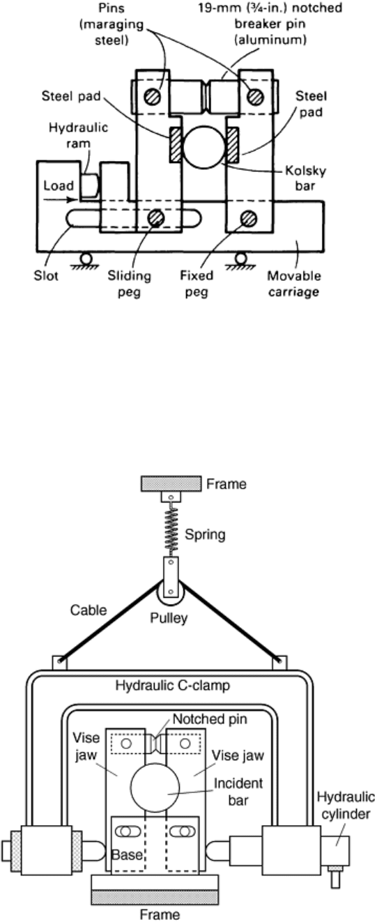
Fig. 4 Clamp designed by Duffy for the torsional Kolsky bar. Source: Ref 18
A variation of this design introduced by Gilat is illustrated in Fig. 5. In this design, both arms can slide at the
bottom. The clamp is tightened by a hydraulic C-clamp that pushes the lower ends of the clamp arms against
each other. The hydraulic C-clamp is attached to the frame by means of a cable, a pulley, and a soft spring. In
this way the C-clamp is “floating,” adjusting itself to the location of the bar. In this design, the clamp arms are
shaped to match the circumference of the loading bar. Between tests, the bare surfaces of the bar and the arms
that are in contact are cleaned with acetone to ensure good gripping.
Fig. 5 Clamp designed by Gilat for the torsional Kolsky bar
The amount of torque required to achieve the desired strain rate is a determining factor in selecting the notched-
pin material and the depth of the notch. Pulse rise time is also affected by the choice of material for the notched
pin. The pin material must exhibit minimal ductility, but must not be brittle enough to fracture before the clamp
is tight enough to hold the desired stored torque. Functional pin materials include 6061-T6 and 7075-T6
aluminum alloys. The desired clamping force and fracture point are achieved by varying the depth of the notch.
Steel pins can also be used, but even brittle steels produce a longer rise time than aluminum alloys. It might be
expected that the mass of the clamp would affect the rise time of the pulse, but this appears not to be the case.
The rise time of the pulse can be decreased much more significantly by proper selection of pin material.
Misalignment of the various components of the Kolsky bar can result in a small unloading pulse immediately
preceding the incident loading pulse, particularly if misalignment is caused by the action of the clamp. The
entire clamp mechanism must be allowed to slide relative to the bar. This is achieved with the movable carriage
and the floating hydraulic C-clamp in the designs shown in Fig. 4 and 5, respectively. Care should be taken to
prevent bending of the incident bar when the clamp is tightened.
Explosively Loaded Torsional Kolsky Bar. An explosively loaded torsional Kolsky bar is shown schematically
in Fig. 6. The torsional pulse is generated by the simultaneous detonation of two small charges at the loading
end (Fig. 7). To obtain a pure torque with no bending, each charge must provide an equal impulse, and they
must be detonated at the same instant. The first requirement is met by using equal weights of explosive and the
second by using a single detonator connected to the explosive charge by means of “leaders” that are also made
of the explosive. These leaders are of equal length, and tests have shown that the explosive charges are
detonated less than 0.1 μs apart. Although the pulse that is initiated is almost entirely torsional, some low-
amplitude axial and bending stress pulses are also initiated. The amplitude of these undesirable pulses can be
decreased by inserting a mechanical filter in the bar. The filter, resembling a rather stiff bellows, is shown at the
top of Fig. 8. It is made of an aluminum alloy, such as 6061-T6, with relatively high yield stress.
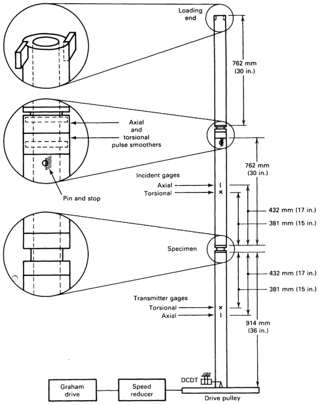
Fig. 6 Schematic of explosively loaded torsional Kolsky bar
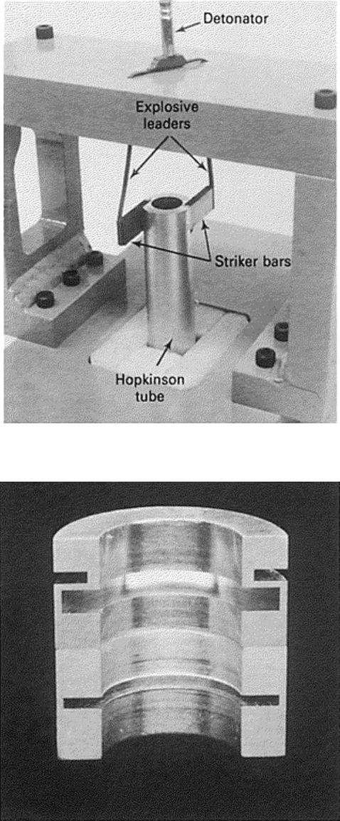
Fig. 7 Loading end of explosively loaded torsional Kolsky bar
Fig. 8 Cross section of pulse filter showing the axial pulse attenuator (top) and the torsional pulse
smoother (bottom)
The advantage of explosive loading is the short rise time in the loading pulse compared to a stored-torque
system. A typical rise time is only 7 to 10 μs, compared with 20 to 40 μs with the stored-torque system,
depending on pulse amplitude. The pulse produced by the explosion at the loading end, however, is neither
“square” nor “smooth.” The amplitude of the pulse varies considerably with time. Because no geometric
dispersion occurs for a torsional pulse in its first mode, the pulse profile remains unchanged as the pulse
propagates toward the specimen. The variation in amplitude is undesirable because it results in loading the
specimen at a variable strain rate. The pulse profile can be smoothed by a second mechanical filter (pulse
smoother). The pulse smoother is a short length of tubing with a narrow neck made of 1100-O aluminum so that
it deforms plastically during the passage of the pulse. It reduces the magnitude of the higher-frequency
components, smoothing the pulse. As shown in Fig. 8, the two filters are placed next to each other in the
incident bar.
The explosive charges produce a relatively short pulse so that the total strain is generally small. With a stored-
torque bar, the distance between the loading end and the clamp can be increased to produce as long a pulse as
the available laboratory space will allow.
Test Specimens
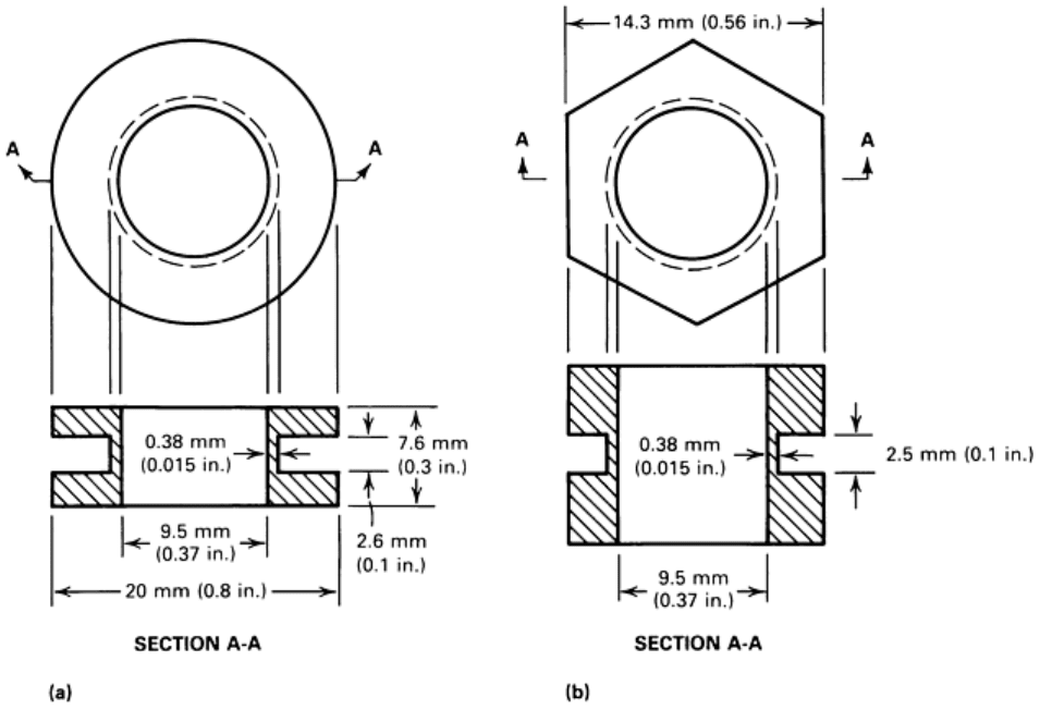
Polycrystalline specimens used in the torsional Kolsky bar experiments usually are short, thin-wall tubes with
integral flanges machined from bar stock (Fig. 9). The specimen is held in position by either cementing its
flanges to the Kolsky bars with epoxy cement, shown in Fig. 9(a), or by mechanical means, shown in Fig. 9(b).
Fig. 9 Details of the polycrystalline specimen used in the torsional Kolsky bar experiment. (a) Tubular
specimen with cylindrical flanges for cementing. (b) Tubular specimen with hexagonal flanges
Cemented connections where the faces of the flanges are glued directly to the bar ends are rigid and provide
sufficient strength for specimens that have relatively low flow stress (e.g., 1100-O aluminum, OFHC copper, or
zinc). Specimens made of materials with higher flow stress can still be cemented by using an adapter that
increases the surface area of the glue. Cemented connections are less convenient to use because it takes a long
time for the epoxy to cure and the bar ends have to be cleaned after each test. In addition, cemented connections
cannot be used in tests at elevated temperatures.
Mechanical connections must be as rigid as possible to prevent loss of motion between the specimen and the
bars as the stress pulses pass. Threaded connections do not meet this requirement. However, success has been
achieved using hexagonal flanges on the specimen with matching sockets in the ends of the Kolsky bars. To
prevent lost motion between the socket and the flanges, small set screws are used to hold the specimen flanges
against the driving faces of the hexagonal sockets. For specimen materials with high flow stress, such as alloy
steel, the set screws may not grip the specimen tightly enough to prevent relative rotation. To enhance rigidity,
the hexagonal socket can be filled with warm glycol phthalate, the specimen inserted, and the set screws
tightened.
The dimensions of the flanges and the design of any adapter or mechanical connection device must be such that
the torsional mechanical impedance matches that of the bar so that the stress pulses do not undergo reflection
when propagating through. This condition requires that the product ρcJ is constant along the bar.
The use of short specimens in the torsional Kolsky bar implies that a nearly homogenous state of strain is
obtained after a few reflections of the loading pulse from the ends of the specimen. To examine the
development of the elastic-plastic boundary within the wall thickness of the tubular specimen, a finite-element
analysis of the strain distribution is performed (Ref 19). In this analysis, a bilinear elastic-plastic stress-strain
relation is used with an elastic modulus and a plastic-hardening rate approximately equal to those of
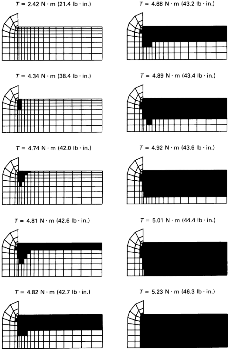
commercially pure aluminum. Figure 10 illustrates the growth of the plastic zone (the dark areas) at various
stages of deformation.
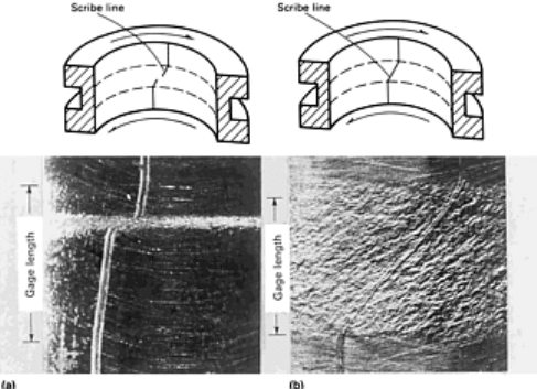
Fig. 10 Results of a finite-element analysis showing the growth of the plastic zone within the tubular
specimen used in the torsional Kolsky bar. Each diagram shows a cross section through half the length of
the tube wall, plus the adjacent flange. The plastic zone is represented by the dark area and the applied
torque is T. Source: Ref 19
The plastic zone begins at the reentrant corner between the thin-wall tube and the flange, and from there
spreads gradually throughout the thickness of the wall. Each diagram in Fig. 10 represents one quarter of the
cross section of the tube and the adjacent part of the flange; thus, the central axis of the specimen lies below in
each diagram. The values of the applied torque are given.
The plastic zone proceeds radially toward the inside wall surface and then across the gage length along the
outside surface of the specimen. The plastic zone is contained until almost the entire specimen begins to flow.
These results are based on a static analysis, but because the wavelength of the pulse is much longer than the
specimen, these data can be applied to the dynamic deformation and appear to agree well with experimental
results.
With continued loading into the plastic range, the strain distribution in the thin-wall tube may not remain
homogeneous. For example, depending on the material, shear bands may form that completely encircle the thin-
wall tube. Whenever the strain is not homogeneous, interpretation of the strain gage records is significantly
altered because the strain rate and, hence, the strain that are calculated from the strain-gage records are average
values based on the assumption that the deformation is homogeneous. If shear bands develop, they are not
encountered until some plastic deformation has accumulated. For instance, Costin et al. observed shear bands in
1018 cold-rolled steel at plastic strain of 8 to 10% (Ref 14). The presence of shear bands in a thin-wall tubular
specimen is easy to detect by scribing fine axial lines on the inside-wall surface of the specimen before loading.
If the strain remains homogeneous throughout the deformation process, after testing, each of these lines appears
tilted at the shear angle within the gage length of the specimen, but remains straight and axial in the flange area
(Fig. 11b). Any departure from a straight line within the gage length is evidence of nonhomogeneous strain.
When nonuniform strain is present, as in the case of a shear band, the lines depart drastically from straight lines
(Fig. 11a).
Fig. 11 Section of specimen showing scribe line after testing. (a) Specimen with nonhomogenous strain
distribution due to the formation of a shear band. (b) Specimen with homogenous strain distribution
Single-crystal specimens can be tested in the torsional Kolsky bar using a small rectangular parallelepiped. A
matched set of four single-crystal specimens with the same crystallographic orientation are tested together. The
specimens are arranged circumferentially at 90° intervals (Fig. 12).
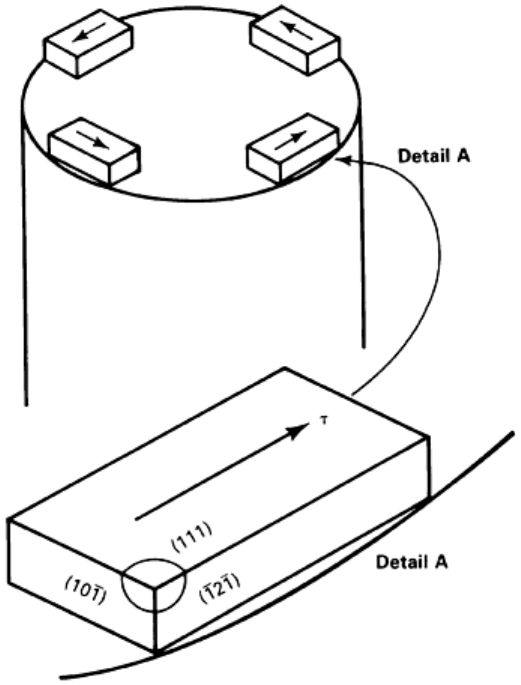
Fig. 12 Aluminum single-crystal specimens showing the arrangement relative to the Kolsky bar
The specimens are secured with an epoxy cement. These cements are sufficiently strong to test pure metals,
which generally have a low flow stress. With strong metals, the epoxy might break before any significant
amount of strain accumulates. Each test yields the average stress-strain properties of the four specimens (Ref
20).
Measuring the Waves in the Bars
The torsional waves in the Kolsky bars are detected by electrical-resistance strain gages. At each measuring
station, four strain gages, equally spaced around the circumference, are placed on the bar. Two gages on
opposite sides are at +45° to the axis of the bar, and the other two gages, also on opposite sides but rotated 90°
relative to the first two, are at -45° to the axis of the bar. The four gages are connected in a four-arm
Wheatstone bridge.
Location of Measuring Stations. A wave-characteristic diagram for a stored-torque Kolsky bar that shows the
positions of the wave fronts with time is shown in Fig. 3. Upon release of the clamp, the torsional pulse, with a
torque of amplitude equal to half that of the stored torque, propagates down the bar toward the specimen.
Simultaneously, an unloading pulse of equal magnitude propagates from the clamp toward the loading pulley.
The torsional mechanical impedance of the pulley is sufficiently large so that the reflected unloading wave
reduces the torque in the incident bar to zero as it propagates back along the bar. The duration of the loading
pulse is the time required for the pulse to travel twice the distance along the bar between the clamp and the
loading end.
The waves are measured on the incident and transmitter bars. On the transmitter bar, the wave is measured in
one location. On the incident bar, the wave can be measured at either one or two locations.
When the pulse on the incident bar is measured at one location, as shown in Fig. 3, the location must be at a
sufficient distance from the specimen so that a clear record of both the incident and the reflected pulses is
obtained without overlap or interference. For example, if the distance between the clamp and the loading end is
760 mm (30 in.), the pulse length would be 490 μs for an aluminum bar with a shear wave speed of 3100 m/s
(10,200 ft/s). To ensure that the reflected pulse does not overlap with the incident pulse at the gage station and
thus cause interference, the gage station must be placed at least 760 mm (30 in.) from the specimen.
Furthermore, to ensure that the stress in the bar returns to zero after the pulse has passed, the station should be
located at an even greater distance from the specimen. For example, for the bar shown in Fig. 3, the gage station
is located 915 mm (36 in.) from the specimen. A gage station for monitoring the transmitted pulse is located at
the same distance from the specimen (915 mm, or 36 in.). Figure 13 shows an oscilloscope record from a test
with the stored-torque Kolsky bar in which the pulse on the incident bar was recorded at one location.
Fig. 13 Oscilloscope record from a test with a stored-torque Kolsky bar in which the pulse in the incident
bar is recorded at one gage station. Each horizontal division equals 200 μs. Transmitted output
magnified 2×. Fracture of the specimen causes transmitted pulse magnitude to drop to zero.
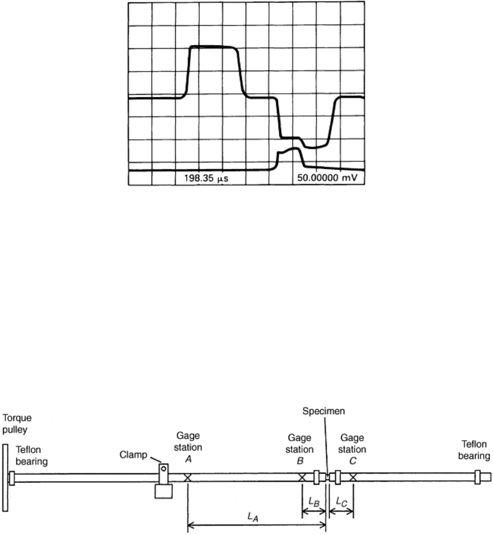
When the pulse in the incident bar is measured at two locations, one station is located near the clamp and the
other near the specimen (Fig. 14). The angular velocity and torque at the interface between the incident bar and
the specimen can be determined from the recorded pulses in the two stations. The duration of the experiment
that can be analyzed depends on the location of the gage stations. A longer duration is obtained if stations A and
B are placed close to the clamp and the specimen, respectively. To have a uniform wave in the gage station A, it
should not be located too close to the clamp (a distance of 3–4 bar diameters appears to be appropriate). The
length of the clamped section of the incident bar should be designed such that the reflected wave from the
loading wheel reaches gage station A just after the reflected wave from the specimen arrives there. When
processing the data it is also convenient (though not necessary) to place gage stations B and C at the same
distance from the specimen. Figure 15 shows oscilloscope records from a test with the stored-torque Kolsky bar
in which the pulse on the incident bar was recorded at two locations (Ref 21).
Fig. 14 Schematic of a torsional Kolsky bar with two gage stations on the incident bar
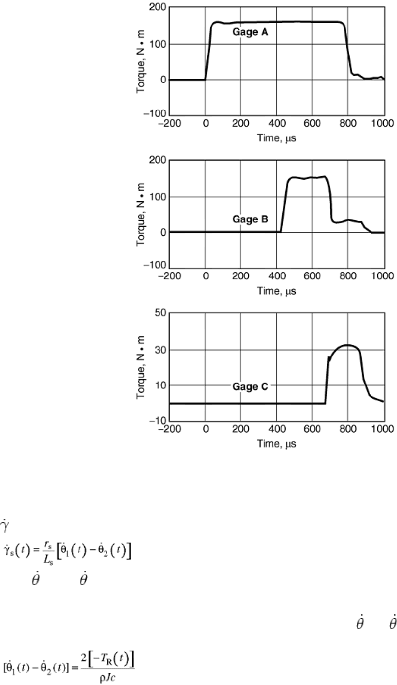
Fig. 15 Oscilloscope record from a test with a stored-torque Kolsky bar in which the pulse in the incident
bar is recorded at two gage stations. Source: Ref 21
Calculating Stress, Strain, and Strain Rate. The average shear strain rate in the specimen as a function of time,
s
(t), is determined from the difference in the angular velocity between its two ends by:
(Eq 4)
where
1
(t) and
2
(t) are the angular velocities of the specimen ends where it attaches to the incident and
transmitter bars, respectively; r
s
is the mean radius of the thin-wall specimen; and L
s
is the length of the
specimen.
When one gage station is used to measure the waves on the incident bar [
1
(t) -
2
(t)] is determined from the
reflected pulse by:
(Eq 5)
where T
R
(t) is the amplitude of the torque of the reflected pulse. Equation 5 is derived by assuming that the
specimen is under a uniform state of stress such that the torque at both ends is equal. The torque, T, at a gage
station is related to the measured shear strain on the surface of the bar, γ, by:
