ASM Metals HandBook Vol. 17 - Nondestructive Evaluation and Quality Control
Подождите немного. Документ загружается.


Acoustic microscopes are practical tools that have emerged from the laboratory to find useful applications within
industry. They can be applied to a broad range of problems that previously had no solutions, and they have been
especially useful in solving problems with new high-technology materials and components not previously available. The
three acoustic microscope types can be as different from each other as are microradiography and electron microscopy.
This discussion should provide the potential user with an awareness of the techniques and their distinctions in order to
maximize the opportunities for the successful use of acoustic microscopy.
References
1.
A. Korpel, L.W. Kessler, and P.R. Palermo, Acoustic Microscope Operating at 100 MHz, Nature,
Vol 232
(No. 5306), 1970, p 110-111
2.
Product Bulletin, Sonoscan, Inc.
3.
R.A. Lemons and C.F. Quate, Acoustic Microscope--Scanning Version, Appl. Phys. Lett.,
Vol 24 (No. 4),
1974, p 163-165
Acoustic Microscopy
Lawrence W. Kessler, Sonoscan, Inc.
Fundamentals of Acoustic Microscopy Methods
As a general comparison between the methods, the scanning laser acoustic microscope is primarily a transmission mode
instrument that creates true real-time images of a sample throughout its entire thickness (reflection mode is sometimes
employed). In operation, ultrasound is introduced to the bottom surface of the sample by a piezoelectric transducer, and
the transmitted wave is detected on the top side by a rapidly scanning laser beam.
The other two types of microscopes are primarily reflection mode instruments that use a transducer with an acoustic lens
to focus the wave at or below the sample surface. The transducer is mechanically translated (scanned) across the sample
in a raster fashion to create the image. The C-mode scanning acoustic microscope can image several millimeters or more
into most samples and is ideal for analyzing at a specific depth. Because of a very large top surface reflection from the
sample, this type of microscope is not effective in the zone immediately below the surface unless the Rayleigh-wave
mode to scan near-surface regions is used along with wide-aperture transducers. The scanning acoustic microscope uses
this Rayleigh wave mode and is designed for very high resolution images of the surface and near-surface regions of a
sample. Penetration depth is intrinsically limited, however, to only one wavelength of sound because of the geometry of
the lens. For example, at 1 GHz, the penetration limit is about 1 m (40 in.). The C-mode scanning acoustic microscope
is designed for moderate penetration into a sample, and transmission mode imaging is sometimes employed. This
instrument uses a pulse-echo transducer, and the specific depth of view can be electronically gated. More detailed
discussions of each acoustic microscopy technique follow.
SLAM Operating Principles
A collimated plane wave of continuous-wave (CW) ultrasound at frequencies up to several hundred megahertz is
produced by a piezoelectric transducer located beneath the sample, as illustrated in Fig. 1. Because this ultrasound cannot
travel through air (making it an excellent tool for crack, void, and disbond detection), a fluid couplant is used to bring the
ultrasound to the sample. Distilled water, spectrophotometric-grade alcohol, or other more inert fluids can be used,
depending on user concerns for sample contamination. When the ultrasound travels through the sample, the wave is
affected by the homogeneity of the material. Wherever there are anomalies, the ultrasound is differentially attenuated, and
the resulting image reveals characteristic light and dark features, which correspond to the localized acoustic properties of
the sample. Multiple views can be made to determine the specific depth of a defect, as is performed by stereoscopy (Ref
4).
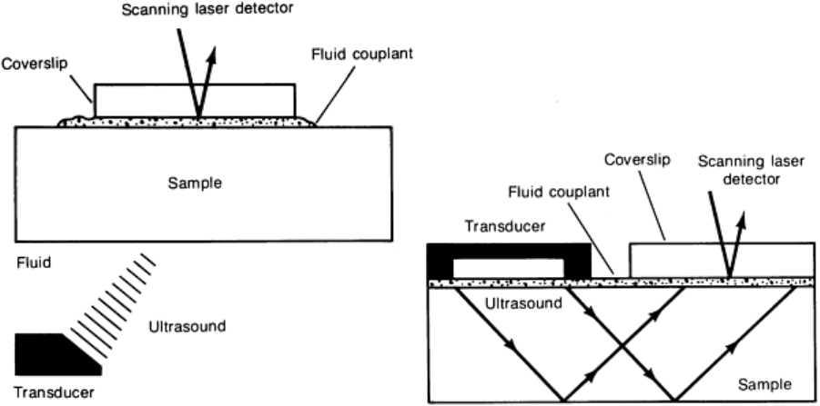
Fig. 1 Simplified view of the methods for producing through transmission and non
collinear reflection mode
acoustic images with the scanning laser acoustic microscope
A laser beam is used as an ultrasound detector by means of sensing the infinitesimal displacements (rippling) at the
surface of the part created by the ultrasound. In typical samples that do not have polished, optically reflective surfaces, a
mirrored plastic block, or coverslip, is placed in close proximity to the surface and is acoustically coupled with fluid. The
laser is focused onto the bottom surface of the coverslip, which has an acoustic pattern that corresponds to the sample
surface. By rapid sweeping of the laser beam, the scanning laser acoustic microscope images are produced in real time
(that is, 30 pictures per second) and are displayed on a high-resolution video monitor. In contrast to other less accurate
uses of the term real time in industry today, the scanning laser acoustic microscope can be used to observe events as they
occur--for example, a crack propagating under an applied stress. The images produced by SLAM are shadowgraph mode
images of structure throughout the thickness of the sample. This provides the distinct advantage of simultaneous viewing
of the entire thickness of the sample, as in x-ray radiography. In situations where it is necessary to focus on one specific
plane, holographic reconstruction of the SLAM data can be employed (Ref 5, 6).
Figure 2 shows a system block diagram for the scanning laser acoustic microscope. In addition to an acoustic image on a
CRT, an optical image is produced by means of the direct scanned laser illumination of the sample surface. For this mode,
the reflective coating on the coverslip is made semi-transparent. The optical image serves as a reference view of the
sample for the operator to consult for landmark information, artifacts, and positioning of the sample to known areas. The
SLAM acoustic images also provide useful and easily interpreted quantitative data about the sample. For example, the
brightness of the image corresponds to the acoustic transmission level. By removing the sample and restoring the image
brightness level with a calibrated electrical attenuator placed between the transducer and its electrical driver, precise
insertion loss data can be obtained (Ref 7, 8). With the acoustic interference mode, the velocity of sound can be measured
in each area of the sample (Ref 9, 10). When these data are used to determine regionally localized acoustic attenuation
loss, modulus of elasticity, and so on, the elastic microstructure can be well characterized.
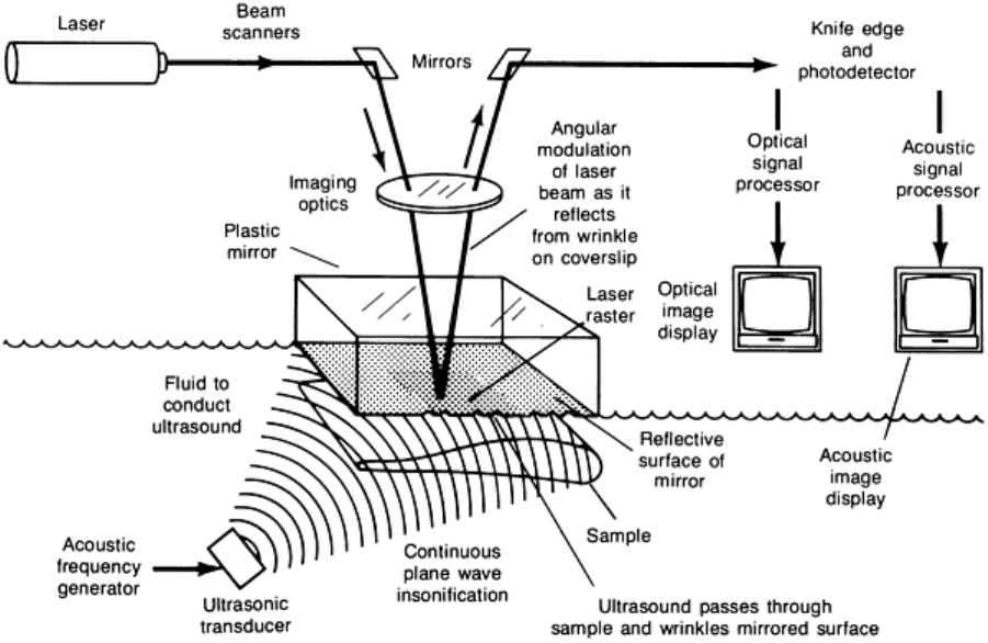
Fig. 2
Schematic showing principal components of a scanning laser acoustic microscope. The unit employs a
plane wave piezoelectric transducer to generate the ultrasound and a focused laser
beam as a point source
detector of the ultrasonic signal. Acoustic images are produced at a rate of 30 images per second.
The simplest geometries for SLAM imaging are flat plates or disks. However, with proper fixturing, complex shapes and
large samples can also be accommodated. For example, tiny hybrid electronic components, large (254 × 254 mm, or 10 ×
10 in.) metal plates, aircraft turbine blades and ceramic engine cylinder liner tubes have been routinely examined by
SLAM.
C-SAM Operating Principles
The C-mode scanning acoustic microscope is primarily a pulse-echo (reflection-type) microscope that generates images
by mechanically scanning a transducer in a raster pattern over the sample. A focused spot of ultrasound is generated by an
acoustic lens assembly at frequencies typically ranging from 10 to 100 MHz. A schematic diagram is shown in Fig. 3.
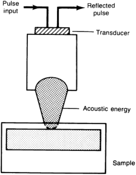
Fig. 3 Schematic of the C-mode scanning acoustic microscope. This instrument incorporates a reflection, pulse-
echo technique that employs a focused
transducer lens to generate and receive the ultrasound signals beneath
the surface of the sample.
The ultrasound is brought to the sample by a coupling medium, usually water or an inert fluid. The angle of the rays from
the lens is generally kept small so that the incident ultrasound does not exceed the critical angle of refraction between the
fluid coupling and the solid sample. Note that the focal distance into the sample is shortened considerably by the liquid-
solid refraction. The transducer alternately acts as sender and receiver, being electronically switched between the transmit
and receive modes. A very short acoustic pulse enters the sample, and return echoes are produced at the sample surface
and at specific interfaces within the part. The return times are a function of the distance from the interface to the
transducer. An oscilloscope display of the echo pattern, known as an A-scan, clearly shows these levels and their time-
distance relationships from the sample surface, as illustrated in Fig. 4. This provides a basis for investigating anomalies at
specific levels within a part. An electronic gate selects information from a specific level to be imaged while it excludes all
other echoes. The gated echo brightness modulates a CRT that is synchronized with the transducer position.
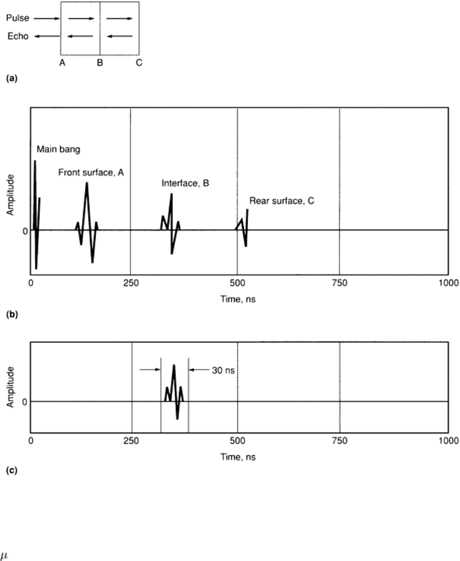
Fig. 4 Signal/source interfaces and A-
scan displays for typical sample. (a) Simplified diagram showing pulses of
ultrasound being reflected at three interfaces: front surface, A; material interface, B; and rear int
erface, C.
Main bang is the background electrical noise produced by transducer excitation. (b) Plot of amplitude versus
time as transducer is switched between transmit and receive modes at each interface during a time span of
under 1 s. (c) Signal at interface B gated for a duration of 30 ns
Compared to older conventional C-scan instruments, which produce a black/white output on thermal paper when a signal
exceeds an operator-selected threshold, the output of the C-mode scanning acoustic microscope is displayed in full gray
scale, in which the gray level is proportional to the amplitude of the interface signal (gray-scale digitization is discussed
in the article "Machine Vision and Robotic Evaluation" in this Volume). The gray scale can be converted into false color,
and as shown in Fig. 5, the images can also be color coded with echo polarity information (Ref 11). That is, positive
echoes, which arise from reflection from a higher-impedance interface, are displayed in a gray scale having one color
scheme, while negative echoes, from reflections off of lower-impedance interfaces are displayed in a different color
scheme. This allows quantitative determination of the nature of the interface within the sample. For example, the echo
amplitude from a plastic-ceramic boundary is very similar to that from a plastic-airgap boundary, except that the echoes
are 180° out of phase. Thus, to determine whether or not an epoxy is bonded to a ceramic, echo amplitude analysis alone
is not sufficient. The color-coded enhanced C-mode scanning acoustic microscope is further differentiated from
conventional C-scan equipment by the speed of the scan. Here, the transducer is positioned by a very fast mechanical
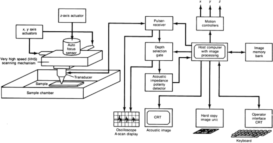
scanner that produces images in tens of seconds instead of tens of minutes for typical scan areas to cover the size of an
integrated circuit.
Fig. 5 Schematic and block diagram of the C-
mode scanning acoustic microscope. The instrument employs a
very high speed mechanical scanner and an acoustic impedance polarity detector to produce high-resolution C-
scan images.
With regard to the depth zone within a sample that is accessible by C-SAM techniques, it is well known that the large
echo from a liquid/solid interface (the top surface of the sample) masks the small echoes that may occur near the surface
within the solid material. This characteristic is known as the dead zone, and its size is usually of the order of a few
wavelengths of sound or more. Far below the surface, the maximum depth of penetration is determined by the attenuation
losses in the sample and by the geometric refraction of the acoustic rays, which shorten the lens focus by the solid
material. Therefore, depending on the depth of interest within a sample, a proper transducer and lens must be used for
optimum results.
SAM Operating Principles
The scanning acoustic microscope is primarily a reflection-type microscope that generates very high resolution images of
surface and near-surface features of a sample by mechanically scanning a transducer in a raster pattern over the sample
(Fig. 6 and 7). In the normal mode, an image is generated from echo amplitude data over an x,y scanned field-of-view. As
with SLAM, a transmission interference mode can be configured for velocity of sound measurements. In contrast to C-
SAM, a more highly focused spot of ultrasound is generated by a very wide angle acoustic lens assembly at frequencies
typically ranging from 100 to 2000 MHz. The angle of the sound rays is well beyond the critical cutoff angle, so that there
is essentially no wave propagation into the material. There is a Rayleigh (surface) wave at the interface and an evanescent
wave that reaches to about one wavelength depth below the surface. As in the other techniques, the ultrasound is brought
to the sample by a coupling medium, usually water or an inert fluid. The transducer alternately acts as sender and
receiver, being electronically switched between the transmit and receive modes. However, instead of a short pulse of
acoustic energy, a long pulse of gated radio-frequency (RF) energy is used. No range gating is possible, as in C-SAM,
because of the basic design concept of the SAM system. The returned acoustic signal level is determined by the elastic
properties of the material at the near-surface zone. The returned signal level modulates a CRT, which is synchronized
with the transducer position. In this way, images are produced in a raster scan on the CRT. As with C-SAM, complete
images are produced in about 10 s.
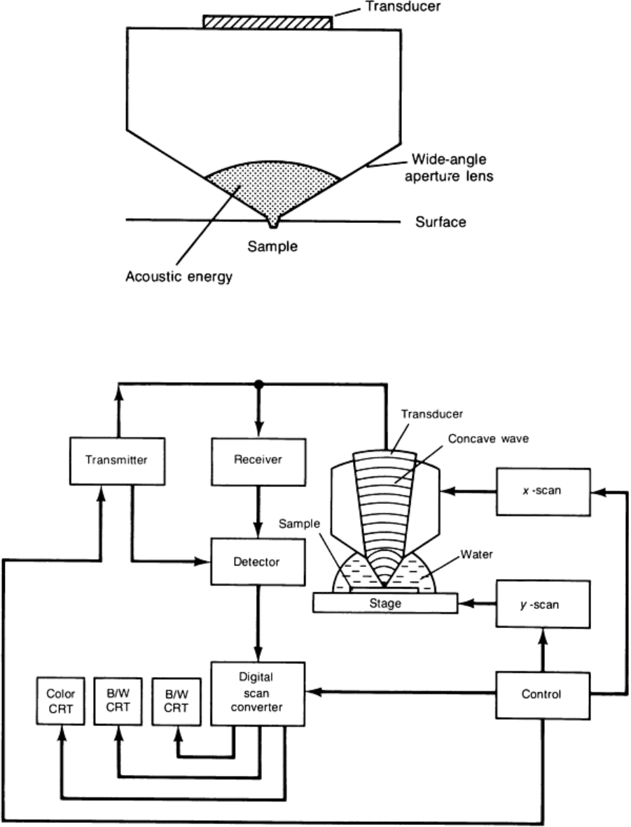
Fig. 6 Schematic of the scanning acoustic microscope lens used for interrogating the surface zone of a sample
Fig. 7 Block diagram of a reflective-
type SAM system that uses mechanical scanning of a highly focused
transducer to investigate the surface zone of a sample at high magnification
With the SAM technique operating at very high frequencies, it is possible to achieve resolution approaching that of a
conventional optical microscope. This technique is employed in much the same way as an optical microscope, with the
important exception that the information obtained relates to the elastic properties of the material. Even higher resolution
than an optical microscope can be obtained by lowering the temperature of operation to near 0 K and using liquid helium

as a coupling fluid. The wavelength in the liquid helium is very short compared to that of water, and submicron resolution
can be obtained (Ref 12).
The SAM technique has also been found to be useful for characterizing the elastic properties of a sample over a
microscopic-size area, which is determined by the focal-spot size of the transducer. In this method, the reflected signal
level is plotted as a function of the distance between the sample and the lens. Because of the leaky surface waves
generated by mode conversion at the liquid/solid interface as the sample is defocused toward the lens, an interference
signal is produced between the mode converted waves and the direct interface reflection. The curve obtained is known as
the V(z) curve; by analyzing the periodicity of the curve, the surface wave velocity can be determined. Furthermore,
defocusing the lens enhances the contrast of surface features that do not otherwise appear in the acoustic image (Ref 13,
14). In addition, by using a cylindrical lens instead of a spherical lens, the anisotropy of materials can be uniquely
characterized (Ref 15).
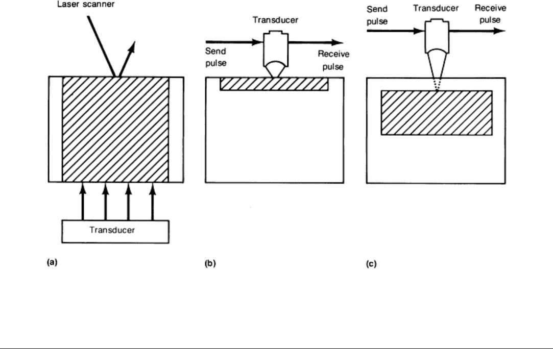
Comparison of Methods to Optimize Use of Techniques
Figure 8 illustrates the zones of application for all three types of acoustic microscopy techniques. The differences are
substantial with regard to the potential for visualizing features within a sample, and they should be carefully weighed
before a particular method is selected. Table 1 lists some of the major advantages and benefits of the techniques.
However, generalizations are sometimes difficult to make. Proposed or laboratory-demonstrated solutions to some of the
limitations of each technique may already exist. Table 1 was prepared on the basis of instrumentation and techniques that
are commercially available and therefore should be used only as a general guide.
Table 1 Comparison of industrial acoustic microscopy techniques
Parameter SLAM C-SAM
SAM
General
description
Utilizes CW, plane wave
ultrasonic illumination of sample
and scanning focused laser beam
detection of ultrasound;
simultaneous optical images and
acoustic images are produced.
SLAM produces images in real
time, which is the fastest of all
acoustic microscopy techniques.
High-resolution focused-beam C-scan
(a)
.
Utilizes pulse-echo mode and has full
gray-scale image output. Images are
produced by mechanically scanning the
transducer over the sample area.
Utilizes very highly focused acoustic
lenses to image exterior surfaces by
means of surface acoustic wave
generation. Images are produced by
mechanically scanning the
transducer over the sample area.
SAM produces the highest resolution
of all acoustic microscopy
techniques.
Primary use Nondestructive testing and
materials characterization
Nondestructive testing and materials
characterization
Materials characterization and
research
Frequency
range
10-500 MHz 10-100 MHz
100 MHz-2 GHz
Resolution Resolution limited to the
wavelength of ultrasound within
the sample material
Resolution limited to the wavelength of
ultrasound within the sample material,
multiplied by a factor, typically 2-10, due
to the lens design
Resolution limited to the wavelength
of ultrasound within the coupling
fluid at the surface of the sample
Imaging mode Through transmission
(primarily); off-axis reflection;
orthoscopic view of sample
Reflection (primarily); orthoscopic view
of sample
Reflection (only); orthoscopic view
of sample
Image
information
Image produced is an acoustic
shadowgraph representing the
entire thickness of the sample.
Image is produced at any selected depth
within the sample, but is affected by
wave propagation through all the levels
prior to the focus location.
Image is produced only at the
sample surface, and the depth of the
information extends into the
material a distance of one

wavelength of sound.
Ultrasound
mode
Continuous-wave and
frequency-modulated ultrasound
waves
Short pulses of ultrasound, less than a
few cycles of RF in duration
Gated RF (or tone burst) containing
many cycles (10-100) of RF at
frequency selected
Ultrasound
signal timing
Not applicable due to CW Echoes are spread out in time, and one is
selected and electronically gated for
desired image depth within sample.
Gated at the surface of the sample
where virtually all the ultrasound is
reflected. There are no subsurface
echoes to select.
Transducer
type
Plane wave transducer for
sample illumination and focused
laser beam for detection
Focused transducer used for transmit and
receive mode. The angle of the rays is
less than the critical angles between the
coupling fluid and the sample. This is
known as a low-numerical-aperture
transducer.
Focused transducer in which the
geometric angle of the rays is much
greater than the critical angles in
order to excite surface modes. This
is known as a high-numerical-
aperture transducer.
Image outputs Amplitude mode: Records level
of ultrasound transmission at
each x,y coordinate of the scan
Interference mode: Records
velocity of sound variations
within sample over the field-of-
view at each frequency
Frequency scan mode: Similar to
amplitude mode except that the
insonification frequency is swept
over a range to eliminate speckle
and other artifacts of coherent
imaging
Optical mode: Laser scanned
optical image produced in
synchrony with the acoustic
images
C-mode: Records echo amplitudes at
each x,y coordinate of the scan; image
output on CRT
A-scan: Oscilloscope display of the echo
pattern as a function of time (distance
into sample) at each x,y coordinate. This
can be used to measure the depth of a
feature or the velocity of sound in the
material. The A-scan is used to determine
the setting of the echo gate, which is
critical to the composition and
interpretation of the images.
Normal mode: Records reflected
energy from surface at each x,y
position. Image output on CRT.
V(z), or acoustic material signature
graph, records the change in
reflected signal level at any x,y
coordinate as the z position is varied
(Ref 12, 13, 14). This will
characterize the material by means
of its surface acoustic wave velocity.
Interference mode: Records velocity
of sound variations within sample
over the field-of-view at each
frequency
Depth of
penetration
Penetration is limited by
acoustic attenuation
characteristic of sample.
In addition to attenuation by the sample,
penetration is limited by focal length of
lens and geometric refraction of the rays,
which causes shortening of the focus
position below the surface. There is also
a dead zone just under the surface due to
the large-amplitude front-surface echo,
which masks smaller signals occurring
immediately thereafter. This can be
rectified with a high-numerical-aperture
transducer.
Limited to a distance of one
wavelength of sound below the
surface. There is essentially no wave
propagation into the sample.
Imaging speed True real-time imaging: 30
frames/s; fastest of all acoustic
microscopes
10 s to 30 min per frame; varies greatly
among manufacturers
10 to 20 s/frame
New
developments
Holographic reconstruction of
each plane through the depth
of the sample (Ref 5, 6)
Acoustic impedance polarity detector
to characterize the physical properties
of the echo producing interfaces (Ref
11)
Low-temperature liquid helium
stages for extremely high resolution
images (Ref 15)
(a)
C-scan produces ultrasonic images by mechanically translating a pulsed transducer in an x,y plane above a sample while recording the echo
amplitude within a preset electronic time gate. The transducer may be planar or focused. The frequencies of operation are typically 1-10
MHz, and the data are usually displayed as a binary brightness level on a hard copy output unit, such as thermal paper. A threshold level
selected by the operator determines the transition between what amplitude of echo is displayed as a bright or dark image print.
Fig. 8
Simplified comparison of three acoustic microscopy techniques, particularly their zones of application
(crosshatched area) within a sample. (a) SLAM. (b) SAM. (c) C-SAM
References cited in this section
4. L.W. Kessler and D.E. Yuhas, Acoustic Microscopy--1979, Proc. of IEEE,
Vol 67 (No. 4), April 1979, p
526-536
5.
Z.C. Lin, H. Lee, G. Wade, M.G. Oravecz, and L.W. Kessler, Holographic Image Reconstruction in
Scanning Laser Acoustic Microscopy, Trans. IEEE, Vol UFFC-34 (No. 3), May 1987, p 293-300
6.
B.Y. Yu, M.G. Oravecz, and L.W. Kessler, "Multimedia Holographic Image Reconstruction in a Scanning
Laser Acoustic Microscope," Paper presented at the 16th International Symposium on Acoustical Imaging
(Chicago, IL), Sonoscan, Inc., June 1987; L.W. Kessler, Ed., Acoustical Imaging,
Vol 16, Plenum Press,
1988, p 535-542
7. L.W. Kessler, VHF Ultrasonic Attenuation in Mammalian Tissue, Acoust. Soc. Am.,
Vol 53 (No. 6), 1973, p
1759-1760
8. M.G. Oravecz, Quantitative Scanning Laser Acoustic Microscopy: Attenuation, J. Phys. (Orsay),
Vol 46,
Conf. C10, Supplement 12, Dec 1985, p 751-754
9.
S.A. Goss and W.D. O'Brien, Jr., Direct Ultrasonic Velocity Measurements of Mammalian Collagen
Threads, Acoust. Soc. Am., Vol 65 (No. 2), 1979, p 507-511
10.
M.G. Oravecz and S. Lees, Acoustic Spectral Interferometry: A New Method for Sonic Velocity
Determination, in Acoustical Imaging,
Vol 13, M. Kaveh, R.K. Mueller, and T.F. Greenleaf, Ed., Plenum
Press, 1984, p 397-408
11.
F.J. Cichanski, Method and System for Dual Phase Scanning Acoustic Microscopy, Patent Pending
12.
J.S. Foster and D. Rugar, Low-Temperature Acoustic Microscopy, Trans. IEEE, Vol SU-32, 1985, p 139-
