ASM Metals HandBook Vol. 17 - Nondestructive Evaluation and Quality Control
Подождите немного. Документ загружается.

(Eq 1)
The gage factor is a function of the gage design, as well as the alloy used to make the gage grid, its thermomechanical
history, and, to a lesser extent, the measurement temperature. Gage factors at room temperature for most typical strain
gage alloys range from two to four.
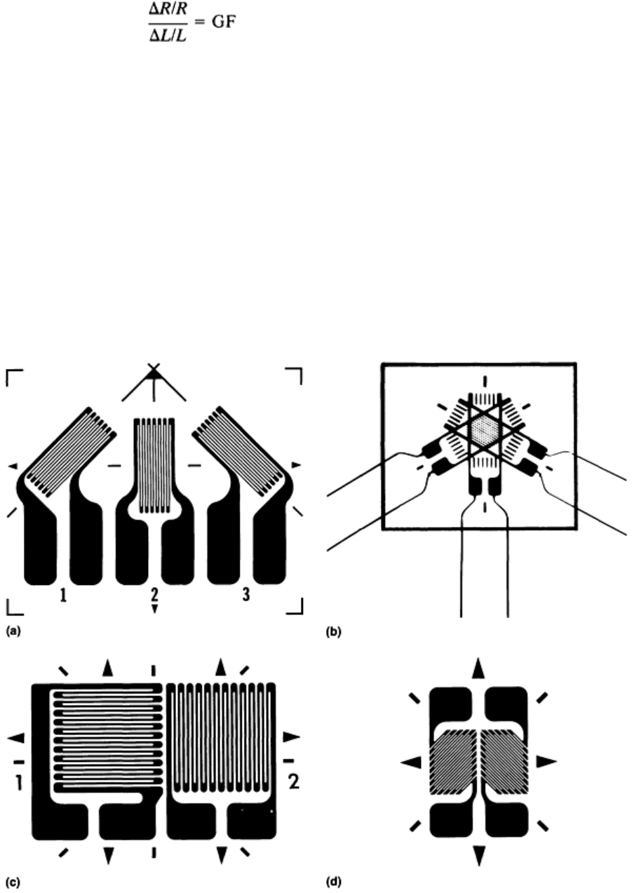
Grid Geometries. Because the grid of a strain gage is designed to measure normal strains in the axial direction of the
grid, various gage geometries are used during strain measurements. Because gages with single grids measure strains in a
single direction, their use should be restricted to well-defined uniaxial stress states, that is, pure tension or compression.
When a point measurement is required in a biaxial stress field and the directions of the principal strains are unknown or
uncertain, a three-element strain gage rosette (Fig. 2a and b) should be used. With grids typically oriented at 0-45-90° or
0-60-120°, these gages enable three separate strain measurements to be made about a point in order to solve for the three
unknowns (the two principal strain magnitudes and their direction). When the principal axes are known, only two
independent strain measurements are required to determine the magnitudes. For these measurements, two-element "T"
rosettes (Fig. 2c) are used. Rosettes are available in both stacked (grids on top of one another) and planar (grids on a
single surface) geometries. Active grid lengths typically vary from 0.4 to 13 mm (0.015 to 0.500 in.) for rosettes.
Fig. 2 Typical grid geometries. (a) Three-element rosette with planar construction. (b) Three-
element rosette
with stacked construction. (c) Two-element T rosette. (d) Two-element pattern for measuring shear strain

Shear strains cannot be directly measured with strain gages. However, the magnitude of shear strain at a point is
always equal to the difference in two orthogonal normal strains at that point with a direction that is intermediate (45°) to
the orthogonal normal strains.
When the direction of the maximum shear strain is known (pure torsion, for example), the magnitude can be determined
by measuring the two associated orthogonal normal strains. To ensure a proper alignment of sensing grids, gages with
special shear patterns are available (Fig. 2d). For these gages, two grids are oriented at right angles to one another and at
45° angles to the longitudinal axis of the gage. When properly connected to a strain indicator, the indicated strain will be
equal to the shear strain along the gage axis.
Gage Materials. The gage user has a choice of foil and backing materials to suit a wide range of performance and
operating conditions. The most widely selected strain-sensing alloy for use on most materials is a copper-nickel alloy
known as constantan. With a gage factor (defined in the section "Gage Performance" in this article) of about 2.1 for most
grid geometries, constantan can be thermomechanically processed to minimize the effects of thermally induced resistance
changes (thermal output) that occur when gages experience a change in temperature while strains are being measured.
The measurement range of constantan gages is generally limited to strains of 5% or less, except for gages made from fully
annealed material, which have a limit of 20%.
For elevated-temperature measurements, that is, up to 290 °C (550 °F) long-term or 400 °C (750 °F) short-term, a nickel-
chromium alloy similar to Karma (Ni-20Cr-3Fe-3Al) is used for strain gage grids. With a gage factor similar to that of
constantan, this alloy exhibits a higher fatigue life. The grids of gages having the greatest resistance to fatigue are made of
iron-nickel-chromium-molybdenum alloy (Iso-elastic). This alloy has a high gage factor (about 3.5), but cannot be treated
to minimize thermal effects. As a result, Iso-elastic gages are normally used only in dynamic applications. The strain
measurement range of both Karma and Iso-elastic gages is limited to strains of 2% or less. Iso-elastic gages become very
nonlinear at strains above 0.5%.
The strain gage backing serves to hold the sensing grid in place. The backing (along with the adhesive) also electrically
isolates the grid from the test specimen and transfers the strains from the surface of the test part to the sensing grid. For
stress analysis work, gage backings are commonly made of a tough, flexible polyimide. For extreme temperatures, that is,
below -45 °C (-50 °F) or above 120 °C (250 °F), a more stable glass-reinforced epoxy phenolic is commonly used.
Gage Installation. The problem of where to install strain gages requires either a fundamental understanding of the
mechanics involved or the use of photoelastic or brittle coatings to locate high and low stress regions. Photoelastic and
brittle coatings will also indicate the directions of the maximum and minimum principal strains.
After the appropriate location is determined, careful installation of the gage is required in order to achieve accurate and
reliable strain measurements. To accomplish this requires strict adherence to the recommended installation procedures
supplied by the gage manufacturer, including the use of the proper accessory tools and supplies.
The adhesive, which must transfer the strain from the specimen surface to the gage backing, is of paramount importance
in gage installation. Specially qualified cyanoacrylate adhesives are popular because of their ease of application and short,
room-temperature curing cycle. However, these adhesives are degraded by time, humidity, elevated temperature, and
moisture absorption. Under these conditions, an epoxy-base strain gage adhesive would be a better selection. In addition
to having higher elongation capabilities, epoxies have longer cure times. Some also require elevated-temperature cures.
Care must be taken not only in selecting the best adhesive but also in choosing the correct leadwires, solders, and
protective coating for the test environment. While most tests are performed in a laboratory-like environment at room
temperature, by using the proper techniques and materials for bonding, wiring, and protecting strain gages, it is possible
to make good strain measurements under a wide variety of difficult environmental conditions over an extended period of
time. Technical data on this subject are available in a variety of forms (training programs, videotapes, publications,
applications engineering assistance) from strain gage manufacturers.
Instrumentation. Because the resistance changes per unit of microstrain ( m/m) are so small (0.00024 ohms/ m/m
for a 120-ohm gage with a gage factor of 2.000), it is usually not practical to measure the resistance directly. As a result,
electrical circuits are commonly employed to convert the resistance changes into a voltage signal, which can be measured
with recording instruments.
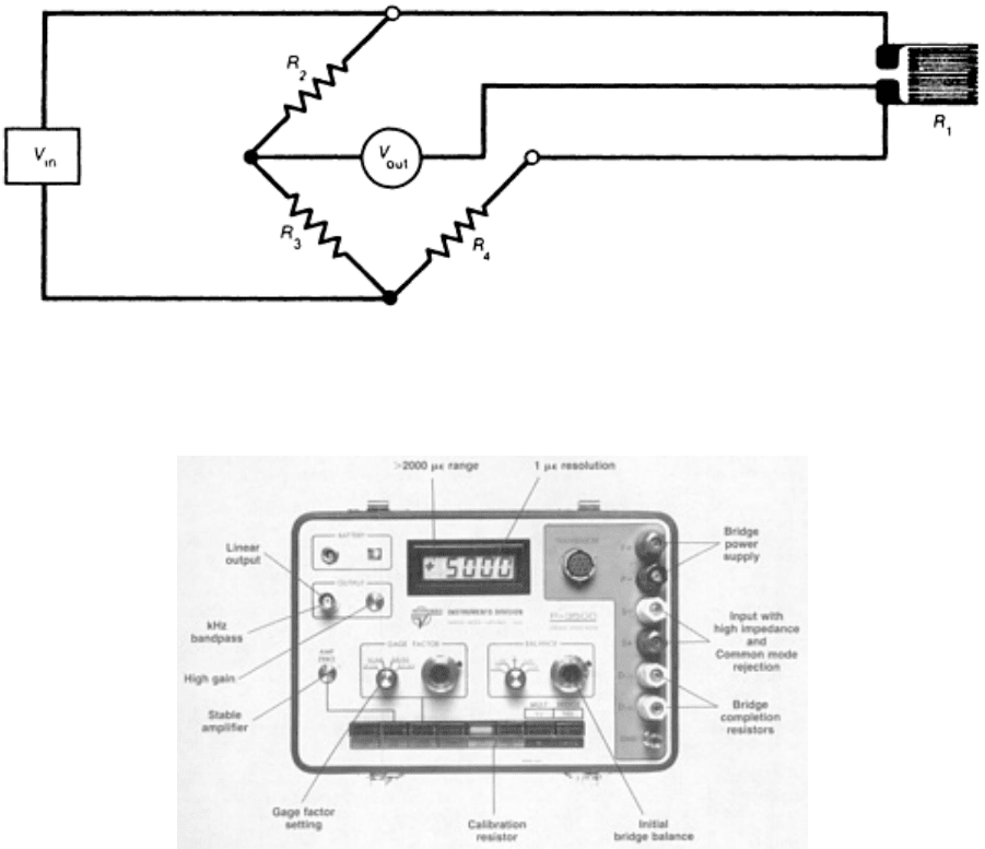
Modern strain gage instruments generally employ a Wheatstone bridge (Fig. 3) as the primary sensing circuit. A stable,
high-gain dc amplifier is then used to amplify the small bridge output signal to a level suitable for driving some form of
display or output device. In addition to these two basic components, a typical strain indicator (Fig. 4) includes the bridge
power supply and built-in bridge completion resistors, along with balance and gain controls, provision for shunt
calibration, and various convenience features.
Fig. 3 Wheatstone bridge configuration with quarter-bridge, three-wire circuit
Fig. 4 Features of a high-quality strain indicator
For a given strain, the bridge output can be increased by increasing the bridge voltage. While it is usually desirable to
obtain as high an output as possible, there are limitations set by the self-heating effects, which vary with the current
through the gage. The power densities that can be tolerated by the gage are strongly influenced by the specimen, which
serves as a heat sink. For most practical purposes, bridge voltages are normally in the range of 1 to 15 V, with most
measurements being made at voltages in the range of 2 to 5 V.
An important feature to be considered when dynamic measurements are involved is the frequency response or bandwidth
of the analog output from the amplifier. Band-width specifications are normally referred to the -0.5 dB (5% loss of
output) or the -3 dB (30% loss of output) point. Errors due to the frequency response of the instrumentation must be
assessed by dynamic calibration with a frequency generator.
The output from the amplifier is normally in the form of an analog voltage (up to 10 Vdc), which can be fed into an
appropriate indicating or recording device. For static measurements, the analog output will typically be fed to an analog-
to-digital converter, with the digital signal being passed to a digital display (often built into the instrument) or to a
computer. For dynamic measurements, the analog voltages are normally fed into an oscilloscope, x-y recorder, magnetic
tape recorder, or recording oscillograph.

Errors. The stability and repeatability of present-day gages and instrumentation enable resolutions of strain as small as 1
m/m. In terms of accuracy, however, measurement errors depend on a number of factors, including, primarily, gage
factor uncertainties, thermal output, signal attenuation in installations with long leadwires, Wheatstone bridge
nonlinearity, gage alignment errors, incomplete transmission of strain through the adhesive, sensitivity of the gage to
transverse strains, and reception of noise from outside the bridge. When these sources of error are properly handled, strain
measurements having inaccuracies that total 1% or less can readily be made. Inaccuracies may be higher at elevated
temperatures.
Strain Measurement for Stress Analysis
L.D. Lineback, Measurements Group, Inc.
Photoelastic Coating Method
Photoelasticity is a visual full-field technique for measuring strain. When a photoelastically active material is strained and
viewed under polarized light, distinct color bands (fringes) are observed (see Fig. 24a in the article "Use of Color for
NDE" in this Volume). Aside from its colorful and aesthetically pleasing character, the photoelastic fringe pattern
provides valuable information for the stress analyst.
Photoelasticity embraces three broad techniques: photoelastic coating, two-dimensional model analysis, and three-
dimensional model analysis. Model analysis is useful at the early design stage of a product, before actual parts are made.
However, the most widely used of the three techniques is the photoelastic coating method, which involves the bonding of
a thin photoelastic layer to the surface of a part. When the part is loaded, the strains on its surface are transmitted to the
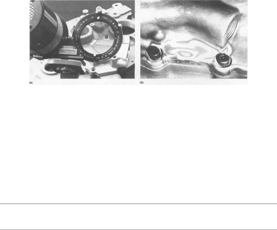
coating. The principal-strain differences in the coating can then be determined with a reflection polariscope (Fig. 5).
Fig. 5 Reflection polariscope with a null-balance compensator being adjusted by the operator
The photoelastic coating method has many advantages over other methods of experimental stress analysis. It enables the
investigator to measure surface strains in parts and structures of virtually any size, shape, or material operating under
actual service conditions at or near room temperature. Additional advantages include:
• The strain field is visually displayed over the entire coated area
• The gage length is effectively zero, permitting accurate measurement of stress gradients
• Yielding is e
asily detected because a portion of the strain pattern remains visible after the loads are
removed
• Assembly strains can be measured
• The combined effects of various load conditions can be observed and measured
• Dynamic analysis can be performed on the part or structure
• Residual stresses can be determined
• Understressed areas can be easily identified for elimination of excess material
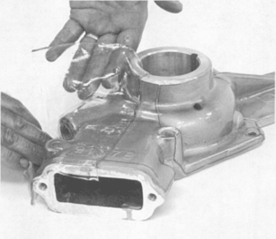
The photoelastic coating material, usually a polymer, can be applied either by bonding prefabricated sheets to the surfaces
of flat specimens or by the contour forming of photoelastic material during polymerization to complex curved surfaces
(Fig. 6).
Fig. 6 Pump housing being coated with photoelastic material
Interpretation of the Photoelastic Pattern. When a photoelastic material is subjected to applied loads, changes in
optical properties take place that are proportional to the strains developed; the material becomes birefringent.
Polarized light passing through a stressed material splits into two rays, each vibrating along a principal stress axis and
traveling at a different speed. A relative phase shift between the two rays produces the color interference pattern, which is
observed and analyzed with the polariscope. With this instrument, the plane of vibration can quickly be established to
permit measurement of the principal stress direction at every point in the field. The phase shift is easily measured by
optical compensation to determine the strain magnitude. In the case of a uniaxial stress condition, the stress is
proportional to the product of the measured phase shift and the fringe value of the coating (microstrain per fringe). In a
biaxial stress condition, the product is equal to the difference in principal strains, or the shear strain.
The photoelastic color sequence observed with increasing stress is black, yellow, red, blue-green, yellow, red, green,
yellow, red, and green (see Fig. 24b in the article "Use of Color for NDE" in this Volume). A constant-color band is a
contour of constant difference in principal strains. A band separating the red and green colors is defined as a fringe. The
higher the fringe order, the higher the strain; the closer the bands are together, the steeper the stress gradient, indicative of
a stress concentration. A uniform color area represents a constant stress area. In brief, the overall stress distribution can be
easily and quickly studied by recognizing fringes, their order, and their location with respect to one another.
At any point on the band of colors, a positive identification of the fringe order is easily made by the null-balance method
with a compensator. The compensator is a device that produces a calibrated phase shift equal in magnitude but opposite in
sign to that occurring in the observed color pattern on the coating. When superimposed, the photoelastic effect is canceled
and a black (zero) fringe is evident. This method of measurement is accurate to one-fiftieth of a fringe, or about 10 to 20
microstrain for most coatings, when coupled with a modern photoelastic data-acquisition system.
At a free boundary, where there is only one nonzero principal stress, tangent to the boundary, the maximum principal
stress can be determined directly. However, because the photoelastic method of strain measurement indicates the
difference in principal strains, it is sometimes necessary for the stress analyst to separate the principal strains at points
other than at a free boundary. Such a situation is illustrated in Fig. 7. Separation requires that a second measurement be
made at each point of interest. The most direct approach is to apply a special strain gage directly to the coating. This gage
measures the sum of any two orthogonal strains at that point (an invariant). Adding the sum and difference of principal
strains together and dividing the result by 2 yields the maximum principal strain at that point.
Fig. 7 Full-field capabi
lity of photoelastic coatings. (a) Measuring the effects of stress concentration near a
corner of a complex part. (b) Regions near the bolts that may contain overlooked assembly stresses
A wide variety of coating materials and adhesives are available. Because the optical signal is a function of both the optical
properties of the material and its thickness, selection of the proper coating should be made on the basis of anticipated
strain levels. Additional considerations in coating selection include reinforcement effect, test temperature, and maximum
elongation. The modulus of elasticity of coating materials ranges from 4 to 3000 MPa (0.6 to 450 ksi). Maximum
allowable elongations are from 3 to 50%, or more. Testing temperatures are normally limited to the vicinity of room
temperature, but the range can be extended up to about 200 °C (400 °F) under certain circumstances. Special equipment is
available for casting contourable sheets from liquid materials.
Reflection polariscopes contain all the optical components necessary for photoelastic coating analysis, including a
suitable light source. Stroboscopic light sources are available for making dynamic measurements. Other common options
include a digital indicator, null-balance compensator (Fig. 5) camera, and telemicroscope.
Strain Measurement for Stress Analysis
L.D. Lineback, Measurements Group, Inc.
Brittle-Coating Method
For this method of strain measurement, a specialty compounded, strain-sensitive lacquer is sprayed onto the surface or
part to be examined. After it has dried and the part has been loaded, the lacquer develops a series of cracks normal to the
direction of the maximum tensile strain on the surface. The crack pattern (Fig. 8) provides an overall picture of the tensile
strain distribution, with an indication of the strain magnitude and direction. Brittle coatings, therefore, are useful for

obtaining a quick indication of likely locations of critical stresses or stress concentrations. They are not used for detailed
measurements, but for a fast, economical means of determining exact locations and orientations for subsequent strain
gage installations.
Fig. 8 Cracks in a brittle coating normal to the maximum tensile strains
The brittle-coating test is particularly suitable for inaccessible areas. For example, in vehicle testing, a part to be
investigated can be coated, assembled in the vehicle, and then disassembled for examination upon completion of a road
test. The resultant crack pattern helps to ensure that any subsequent strain gage investigation is centered at the point of
significant strains. The knowledge that measurements are taken in the correct place can reduce the test time in subsequent
strain gage studies.
Strain Measurement for Stress Analysis
L.D. Lineback, Measurements Group, Inc.
Selected References
• J.W. Dally and W.F. Riley, Experimental Stress Analysis, 2nd ed., McGraw-Hill, 1978
• A.S. Kobayashi, Ed., Handbook on Experimental Mechanics, Prentice-Hall, 1987
• J.M. Whitney, I.M. Daniel, and R.B. Pipes,
Experimental Mechanics of Fiber Reinforced Composite
Materials, 2nd ed., Society for Experimental Mechanics, Inc., 1984
• A.L. Window and G.S. Holister, Ed., Strain Gage Technology, Applied Science, 1982
• F. Zandman, S. Redner, and J.W. Dally, Photoelastic Coatings, The Iowa State University Press, 1977
Digital Image Enhancement
T.N. Claytor and M.H. Jones, Los Alamos National Laboratory

Introduction
IMAGE PROCESSING AND IMAGE ENHANCEMENT have become staple methods for analyzing x-ray, tomographic,
nuclear magnetic resonance (NMR), ultrasonic, thermographic, and other nondestructive evaluation (NDE) data. With
image enhancement, the interpretation of complex data becomes easier for the operator. Fewer errors are made, more
subtle features can be detected, and quantitative measurements are facilitated. The disadvantages of image processing are
that it usually requires much more time than, for example, the visual reading of film, and it requires the operators to have
basic computer skills and a knowledge of image-processing tools. This article presents an overview of image
enhancement techniques with application to the needs of NDE.
Important image-processing functions for NDE applications include:
• Input device control
• Palette adjustment
• Contrast enhancement
• Scaling
• Point, and line density measurement
• A variety of filtering techniques
• Image addition and subtraction
• Trend removal (field flattening)
• Edge enhancement
In addition, there are technique-dependent processing functions, such as tomographic reconstruction or time and
frequency domain processing for NMR and ultrasonic data. Numerous general image processing textbooks, handbooks,
and literature overviews that address techniques used at large, in medical practice, and in industrial NDE are available
(Ref 1, 2, 3, 4, 5, 6, 7, 8, 9, 10).
Acknowledgements
The authors would like to thank their colleagues at several national laboratories, universities, and industrial research
departments for discussions concerning uses of enhancement and for contributions of images to the article.
References
1. W.K. Pratt, Digital Image Processing, John Wiley & Sons, 1978
2. M.H. Jacoby, Image Data Analysis, in Radiography & Radiation Testing, Vol 3, 2nd ed.,
Nondestructive
Testing Handbook, American Society for Nondestructive Testing, 1985
3. R.C. Gonzalez and P. Wintz, Digital Image Processing, Addison-Wesley, 1977
4. G.A. Baxes, Digital Image Processing: A Practical Primer, Prentice-Hall, 1984
5. W. B. Green, Digital Image Processing: A Systems Approach, Van Nostrand Reinhold, 1983
6. H.K. Huang, Element of Digital Radiology: A Professional Handbook and Guide, Prentice-Hall, 1987
7. A. Rosenfeld and A.A. Kak, Digital Picture Processing, Academic Press, 1982
8. K.R. Castleman, Digital Image Processing, Prentice-Hall, 1979
9. B.R. Frieden, Image Enhancement and Restoration, in Picture Processing and Digital Filtering,
Vol 6,
Topics in Applied Physics, T.S. Huang, Ed., Springer-Verlag, 1979, p 177
10.
D.H. Janney and R.P. Kruger, Digital Image Analysis Applied to Industrial Nondestructive Evaluation and
Automated Parts Assembly, Int. Adv. Nondestr. Test., Vol 6, 1979, p 39-93
Digital Image Enhancement
T.N. Claytor and M.H. Jones, Los Alamos National Laboratory
NDE Digital Image Enhancement Systems
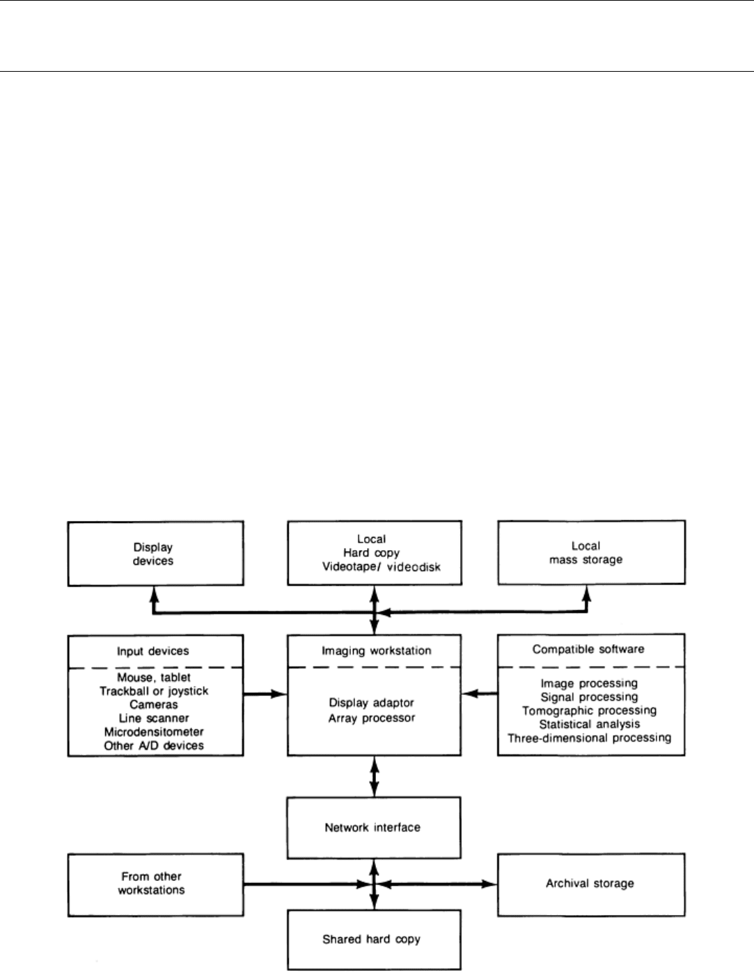
The basic elements of an image-processing station are shown in Fig. 1. The station consists of:
• A computer
• Imaging software
• Mass storage
• Hard copy
• High-resolution display
• Videotape or optical disk input and output
• Other input devices
• Network interface for communication to other workstations
Data can be input from a variety of devices, it can be displayed and manipulated on a screen, the data can be archived,
hard-copies can be made, and information can be exchanged with other computers. Although it is relatively easy to obtain
a subset of the system shown in Fig. 1, it is difficult to find compatible hardware and software for all functions. As has
been the case for the last decade, hardware and software for image-processing applications are rapidly evolving into more
powerful and inexpensive products.
Fig. 1 Typical workstation configuration for use with NDE applications. A/D, analog-to-digital

The selection of a computer and software for processing is dependent mainly on the use and throughput required. Many
acquisition systems, such as real-time radiographic, infrared, and ultrasonic systems, have (optional) custom image-
processing capability. A high-speed computer workstation is usually desirable for multiuser use, for the use of many
computationally intensive algorithms, or for the development of algorithms.
More than 50 computers have been ranked according to time required to solve a standard set of linear equations (Ref 11).
From this ranking, as well as additional independent tests, the approximate time required for various image-processing
functions is given in Table 1 if the code is written in C and the images are 8-bit 1024
2
. These times are very approximate
because:
• The efficiency of the compiler may vary by as much as a factor of two
• Algorithms vary in coding efficiency
• Many image-
processing functions are performed on integer numbers rather than in floating point form
(the speed at which intege
r arithmetic is computed may vary greatly from the floating point value
depending on the machine)
To achieve the fastest processing speeds, the computer can be augmented with an array processor or other hardware that
performs a specific function rapidly. For example, 3 × 3 filtering can be performed on a 1024
2
by 8-bit image in 0.1 s, or
fast Fourier transform (FFT) can be executed on a 1024
2
by 8-bit image in less than 10 s with the aid of an array
processor. As computer processing power increases, more complicated processing functions will become practical for
routine use. Digitally enhanced images are also discussed in the articles "Industrial Computed Tomography," "Thermal
Inspection," and "Acoustic Microscopy" in this Volume.
Table 1 The 8-bit 1024
2
image-processing capabilities of numerous computers
Time per image operation, s
(d)
Relative
performance
Computer
Linear
histogram
equalization
Image
addition
3 × 3
low-
pass
filter
Rotate
3 × 3
Sobel
filter
Fast
Fourier
transform
Class 1 PC-AT 386 20 MHz/wcp
(a)
Sun 3/260
Microvax II
15 32 56 110 135 352
Class 2 Sun 3/260 FPA
(b)
DEC VAX 8550/8800
HP 9000 840/850
MIPS Computer Systems, Inc. M800 w/R
2010 FP
(c)
3.0 6.4 11.2 21.8 27 70
Class 3 HP 9000 835
MIPS Computer Systems, Inc. M120-5
1.1 2.3 4.0 7.8 9.6 25
(a)
Wcp with coprocessor (80836).
(b)
FPA, floating point accelerator.
(c)
FP, floating point.
