ASM Metals HandBook Vol. 17 - Nondestructive Evaluation and Quality Control
Подождите немного. Документ загружается.

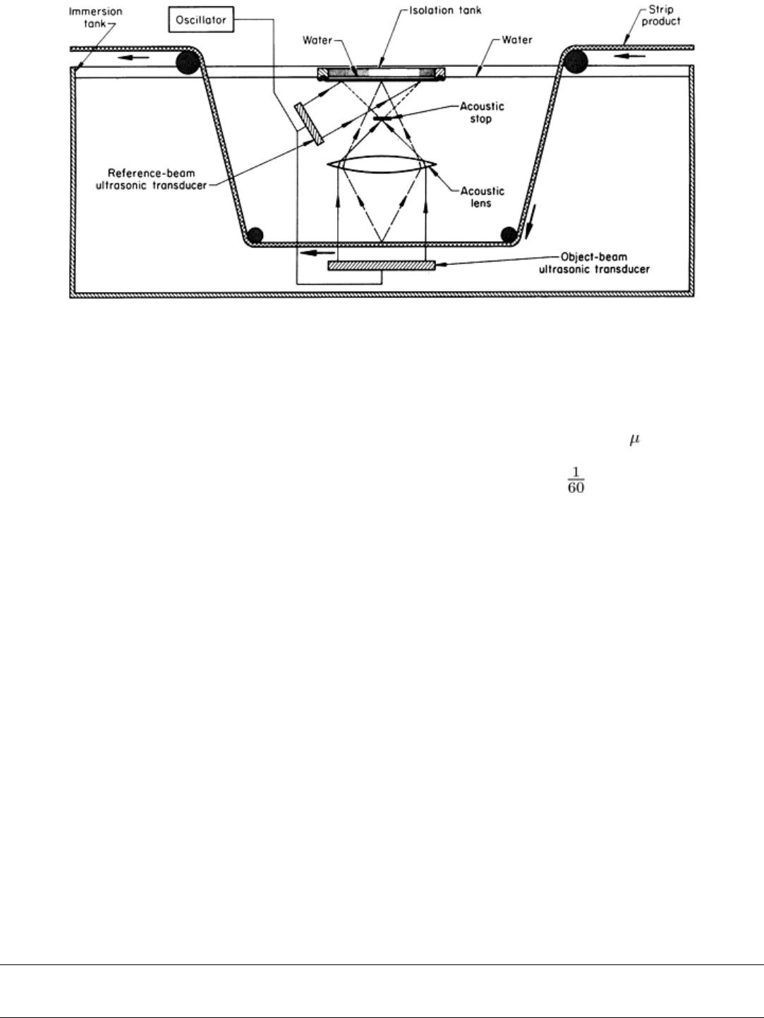
Fig. 2 Schematic of the acoustical portion of a liquid-
surface acoustical holography system that is arranged to
inspect strip products. The optical portion of this system is identical to that in Fig. 1
The system is usually pulsed at a rate compatible with television frame rates. Typically, 60 holograms per second are
produced, which yields flicker-free television images. Because pulse lengths are generally 50 to 300 s, strip velocities of
50 to 300 mm/s (2 to 12 in./s) are possible without blurring. With this arrangement, a photograph of one of the holograms
of the moving object can be taken at any time by setting the shutter speed of the camera at s.
Sensitivity and Resolution. The sensitivity of liquid-surface systems is fixed somewhat by the necessity to produce a
ripple pattern on the liquid surface. For a typical system, the minimum intensity of the ultrasonic beams that can be
detected is about 10
-3
to 10
-6
W/cm
2
.
The detail that can be resolved by liquid-surface acoustical holography is determined by the focal length and linear
aperture of the ultrasonic lens and the wavelength of the ultrasonic beam through the use of the formulas:
Δx = 1.22λ (f/A)
(Eq 1)
Δz = 2λ (f/A)
2
(Eq 2)
where Δx is the resolution in the object plane (that is, lateral resolution), Δz is the resolution perpendicular to the object
plane (that is, depth resolution), λ is the ultrasonic wavelength in the immersion liquid, f is the focal length of the
ultrasonic lens in the immersion liquid, A is the linear aperture (diameter) of the ultrasonic lens, and f/A is the f-stop
number of the ultrasonic lens. For an f/3 lens and a frequency of 5 MHz, flaws in steel or aluminum should be resolved to
about 1 mm (0.04 in.) transversely and about 5 mm (0.20 in.) in depth; that is, small flaws separated by 1 mm (0.04 in.)
transversely or by 5 mm (0.20 in.) in depth can be individually seen, and the size of large flaws can be measured to an
accuracy of 1 mm (0.04 in.) transversely and 5 mm (0.20 in.) in depth.
The values of f-stop number for the ultrasonic lenses used in liquid-surface systems are typically 2 to 3. Although the
resolution of a system increases with the frequency of the ultrasound used, absorption and scattering of the ultrasound
also increase, so that for most industrial testing the frequency range is limited to between 3 and 7 MHz. Sometimes 1
MHz is used, as for rubber products.
Acoustical Holography
Revised by B.P. Hildebrand, Failure Analysis Associates, Inc.
Scanning Acoustical Holography
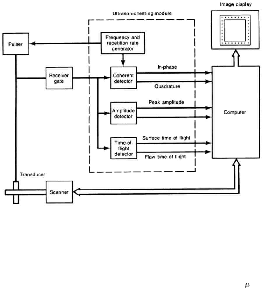
The basic system for scanning acoustical holography is shown in Fig. 3. No reference beam transducer is required in this
system, because electronic phase detection is used to produce the hologram; that is, the required interaction (mixing)
between the piezoelectrically detected object beam signal and the simulated reference beam signal occurs in the electronic
domain. A pulser circuit (consisting of a continuous-wave oscillator and a pulse gate that is triggered by an electronic
clock) and a power amplifier feed a single focused ultrasonic transducer that is scanned over an area above the test object
while alternately transmitting and receiving the ultrasonic signals. The transducer and the test object are immersed in a
water-filled tank or coupled by a water column.
Fig. 3 Block diagram of a commercial ultrasonic and light detection system with capability for A-scan, B-
scan,
and C-scan imaging and holography
The signal is pulsed so that time gating can be used to reject undesired surface echoes. The pulse length can be set to any
desired value from a few periods of the wave frequency to an upper limit of 50% of the time between successive pulses.
Long pulse lengths are used to examine regions lying deep within the metal, while short pulse lengths are required for the
regions near the surface so that transmitted energy is not mixed with reflected energy. The practical limits of the
transducer in a commercial system are a wave frequency of 1 to 10 MHz, a pulse length of 5 to 20 s, and a pulse-
repetition rate of 500 to 1000 per second. The frequency band of a given transducer is relatively narrow (±5% of the mean
frequency).
The transducer is positioned so that its focal point is at the surface of the test object. In this way, the pulse enters the
object and travels through it as a spherical wave front diverging from a point on the surface. Because of refraction at the
water/metal interface, the solid angle formed by the conical beam of energy in the metal will be greater than that formed
by the focused conical beam from the transducer. This is illustrated in Fig. 4 by a longitudinal wave ultrasonic beam
focused at the surface of a steel test object and angled to produce shear waves in the steel. In this situation, the range of
angles of incidence must lie between 15 and 27° to produce only shear waves in the steel, and this range of angles will
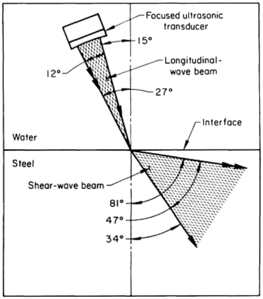
produce a 47° cone of shear-wave energy in the steel. (Refraction at water/metal interfaces is discussed in the article
"Ultrasonic Inspection" in this Volume.)
Fig. 4
Diagram of refraction of a longitudinal wave ultrasonic beam focused on a water/steel interface at
incident angles that produced a shear wave beam in the steel
Either longitudinal or shear waves can be used in the scanning system illustrated in Fig. 3. For the longitudinal wave
mode, the transducer is oriented parallel to the object surface; for the shear wave mode, the transducer is oriented at the
appropriate angle of incidence. With either mode, the wave travels through the object to a flaw, where some of the energy
is reflected back to the transducer. This reflected signal is passed through a transmit-receive switch to a gate that is
triggered by the electronic clock through a time-delay circuit adjusted to compensate for the water-path transit time. This
gate is adjusted in delay and width so that it will pass the reflections from the particular thin segment of the object under
examination during the scan and will reject all others.
The reflected signal is split and sent to two balanced mixers, which are also fed by signals derived from the oscillator.
These signals are phase shifted by 90° from each other. The outputs of the two mixers are therefore equivalent to the sine
and cosine Fourier coefficients of the reflected signal. These coefficients are complete descriptors of the phase and
amplitude of the signal reflected by the flaw and thus constitute a hologram.
The outputs of the balanced mixers are sampled, converted to digital numbers by an analog-to-digital converter, and
stored in the memory of a personal computer. Thus, the result of a two-dimensional scan of a planar surface is a matrix of
complex numbers recorded on the computer disk.
Reconstruction. The results of the detection procedure described above constitute a measurement of the reflected wave
front in the scan plane. Because this wave front resulted from the propagation of the reflected sound from the flaw, it must
have propagated to the scan plane. Therefore, it should be possible to obtain an image of the flaw by propagating the
wave front back to its source. This is done by computer in the following sequence:
• Compute the two-
dimensional Fourier transform of the detected wave front as represented by the matrix
of Fourier coefficients

•
Multiply the transformed data by a complex propagator, the value of which is determined by the
distance to the desired image plane
• Compute the inverse Fourier transform of the back-propagated data to return to image coordinates
• Display the magnitude of the resultant matrix of complex numbers representing the image
All these steps can be accomplished in 20 s on a personal computer interfaced with an array processor. The image is
displayed on a high-resolution black and white or color monitor.
Because there is no conversion of wavelengths, as there was in the original optical reconstruction method, there is no
image distortion. Therefore, the relationship between the size of the image and the size of the object is simply the
magnification factor of the display.
Object Size. Although the scanning system is too slow to be useful for the total inspection of large objects, taking about
10 min for a 152 mm (6 in.) square hologram, the real-time advantage held by the liquid-surface system will disappear
when piezoelectric arrays and associated electronics become available, because electronic scanning can then be used.
Sensitivity and Resolution. Because the scanning system uses a piezoelectric element as a detector, it is more
sensitive than the liquid-surface system by a factor of about 10
6
. For a typical scanning system, the minimum intensity of
ultrasonic beam that can be detected is about 10
-12
W/cm
2
. Mainly because of its much greater sensitivity, scanning
acoustical holography appears to hold more long-term promise for the nondestructive inspection of metal products than
does the liquid-surface system. It also provides an image of the flaw for subsequent determination of both size and depth
within the resolving capacity of the system, which is obtainable from Eq 1 and 2 using the f-stop number of the focused
transducer. Transducers having an f-stop number as low as 2 are available for operation in the longitudinal wave mode.
Acoustical Holography
Revised by B.P. Hildebrand, Failure Analysis Associates, Inc.
Commercial Liquid-Surface Equipment
A schematic of one type of commercially available system for liquid-surface acoustical holography is presented in Fig. 5.
The standard size of the effective object field in this system, which is dependent on the diameters of the two transducers,
is 114 mm (4 in.) in diameter; test objects larger than this can be inspected by moving them through the object field.
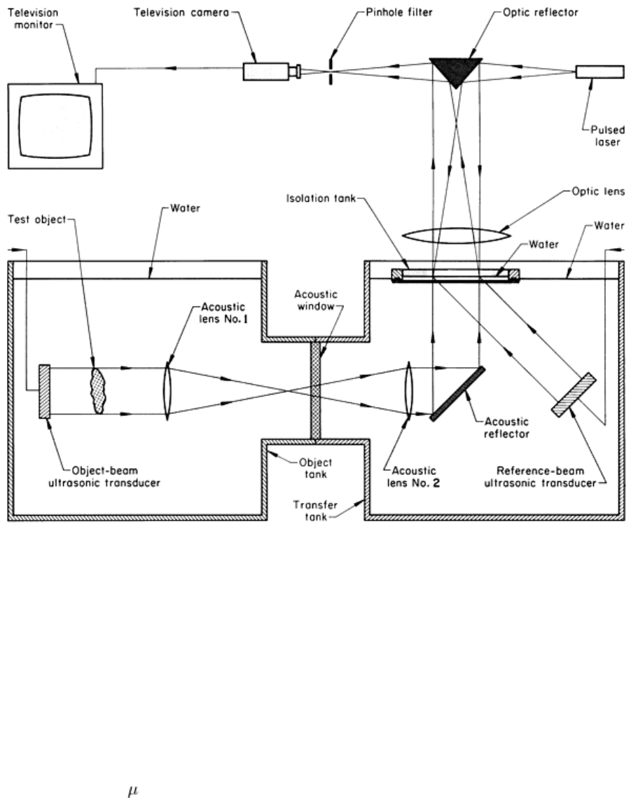
Fig. 5 Schematic of the acoustical and optical systems in the equipment for liquid-
surface acoustical holography
shown in Fig. 6
This system is well stabilized against vibration through the use of an object tank, a transfer tank, and an isolation tank.
The ultrasonic beam is relayed by acoustic lenses from the object tank to the transfer tank through an acoustic window
that connects them. The beam is then relayed by an acoustic reflector to the isolation tank, where the holographic ripple
pattern is formed. Although the acoustic window permits transfer of the ultrasonic beam, it forms an effective barrier to
the transfer of gross movements from the object tank to the transfer tank, where they could disturb the isolation tank and
therefore the ripple pattern.
The pulsed object beam transducer, which is typically 127 mm (5 in.) in diameter, emits a wave train several hundred
wavelengths long (100 to 300 s in duration) 60 times per second. Therefore, the acoustic framing rate is 60 Hz. Similar
wave trains are emitted by the reference beam transducer and are delayed in time to arrive at the liquid surface in
coincidence with the object beam. The delay time, controlled manually by the operator, depends on the position of the
object beam transducer and the thickness of the metal object being examined. The reconstructed image is continuously
displayed on the closed-circuit television monitor or on a ground-glass screen.
This system is essentially stationary because the imaging tank must be leveled and the optical system correspondingly
aligned and because the system is quite large and heavy. Typical dimensions of the equipment are indicated in Fig. 6. It
weighs approximately 450 kg (1000 lb).
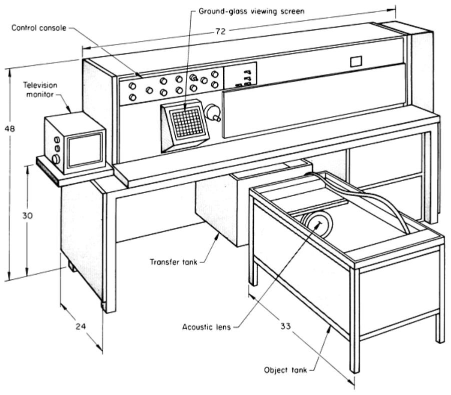
Fig. 6 One type of commercially available equipment for the inspection of small metal objects by liquid-
surface
acoustical holography. Dimensions given in inches
Equipment with a configuration other than that shown in Fig. 5 and 6 has been designed for particular applications. Figure
7 illustrates an alternative configuration used in a piece of liquid-surface equipment designed for the examination of metal
strip. This strip moves continuously through the immersion tank by means of entrance and exit water seals. The
dimensions of this equipment are shown in Fig. 8. Normally, this equipment operates at 3 to 5 MHz, but frequencies of 1
to 9 MHz can be used. The equipment is designed so that neither mechanical vibration nor electrical static is detrimental
to its proper functioning.
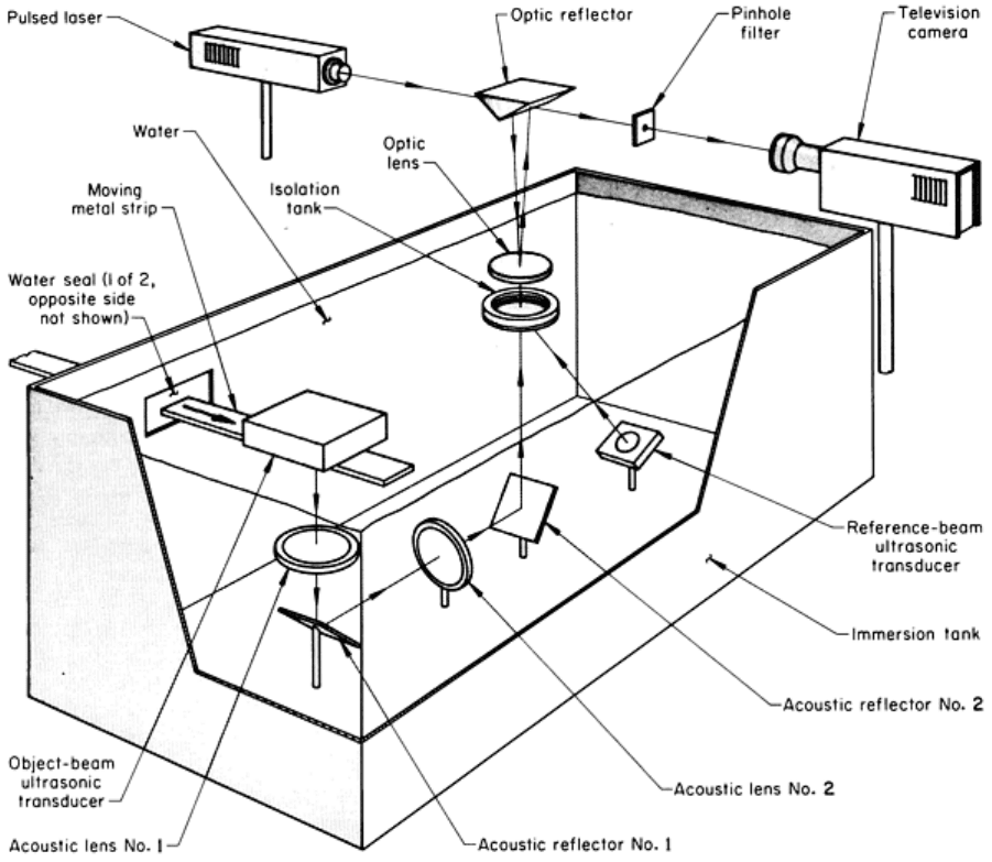
Fig. 7 Schematic of the acoustical and optical systems in the equipment shown in Fig. 6
for the inspection of a
continuously moving strip of metal by liquid-surface acoustical holography
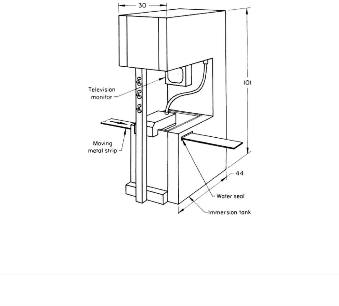
Fig. 8
One type of commercially available equipment for the inspection of a continuously moving strip of metal
by liquid-surface acoustical holography. See Fig. 7
for a diagram of the acoustical and optical systems
employed. Dimensions given in inches
Acoustical Holography
Revised by B.P. Hildebrand, Failure Analysis Associates, Inc.
Commercial Scanning Equipment
Commercially available equipment, such as that described in Ref 2, for inspection by scanning acoustical holography is
often packaged in several units for portability. Figure 9 shows some of the components in one type of commercial system.
Each of these units is readily transportable by one or two persons.
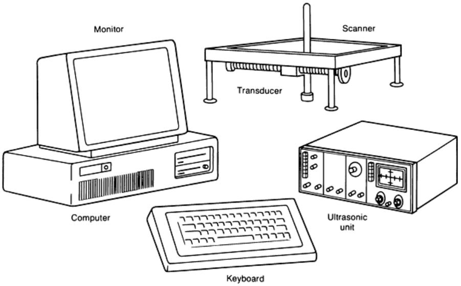
Fig. 9 Key components of a commercially available holography syst
em: personal computer, ultrasonic unit, and
scanner
The attachment fixture is designed to hold the scanner in position even on surfaces with complex contours. The fixture
permits preadjustment of the focal plane of the transducer. After the attachment fixture is in place and aligned, the scanner
is mounted on it. The scanner is digitally controlled and is capable of a raster scan pattern in either the x or the y direction.
There are six settings of index spacing that can be selected for successive scans: 0.15, 0.30, 0.46, 0.60, 0.76, and 0.91 mm
(0.006, 0.012, 0.018, 0.024, 0.030, and 0.036 in.). The largest area that can be recorded in a single hologram with this
scanning system is about 305 mm (12 in.) square. However, by systematically repositioning the scanner, much larger
areas can be examined.
A series of 25 mm (1 in.) diam transducers with 102 mm (4 in.) focal lengths is used in conjunction with this scanner.
Each transducer has a different characteristic operating frequency, so that inspections can be made using any appropriate
frequency within the range of 0.5 to 10 MHz. The transducer and bubbler can be oriented for either straight-beam or
angle-beam testing. A signal gate in the reflection-signal processor unit can be adjusted to reject reflections from all
depths in the object except that under examination. Both the gate width and the gating delay are readily adjustable.
Some models of this equipment also provide switch selectability among A-scan, B-scan, and C-scan modes of display, as
well as a combination B-scan and C-scan mode of display that presents an angled view of the flaw image. This angle can
be varied to enhance visualization of a flaw (see the article "Ultrasonic Inspection" in this Volume for a description of A-
scan, B-scan, and C-scan ultrasonic display modes). The three display modes are illustrated in Fig. 10 for a test block with
flat-bottom holes that simulate flaws. The A-scan display was obtained on an oscilloscope screen. The amplitude of the
reflected signal is displayed in the vertical direction; time of signal flight, which is proportional to depth in the test block,
is displayed horizontally. The B-scan display was obtained by a reconstruction of the hologram produced by orienting the
transducer for angle-beam testing, which provided essentially a profile of the region being examined (in this case, the row
of five holes in the straight portion of the "D"). The C-scan display was obtained with the transducer oriented for straight-
beam testing. The pseudo-three-dimensional image was obtained by the reconstruction of B-scan and C-scan holograms
combined.
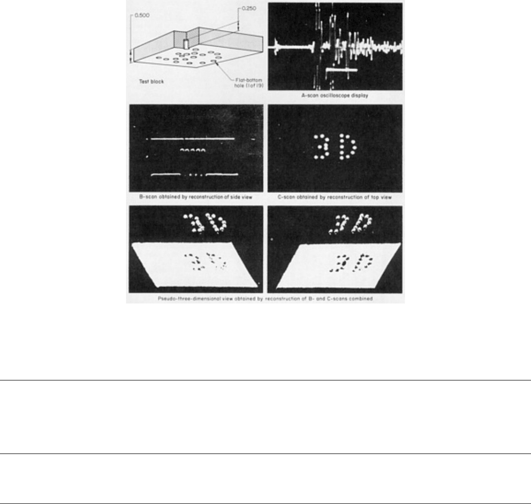
Fig. 10 Test block with flaws simulated by pattern of flat-
bottom holes and displays obtained by scanning the
block with the equipment for scanning acoustical holography. Dimensions given in inches
Reference cited in this section
2.
B.P. Hildebrand, T.J. Davis, A.J. Boland, and R
.L. Silta, A Portable Digital Ultrasonic Holography System
for Imaging Flaws in Heavy Section Materials, IEEE Trans., SV-31, No. 4, 1984, p 287-294
Acoustical Holography
Revised by B.P. Hildebrand, Failure Analysis Associates, Inc.
Comparison of Liquid-Surface and Scanning Systems
The outstanding feature of the liquid-surface system of acoustical holography is that it provides a real-time image, while
the image provided by the scanning system requires reconstruction. The real-time feature makes the liquid-surface system
suitable for the rapid inspection of large amounts of material on a continuous basis. In contrast, inspection with the
scanning system is relatively slow. Photographic or videotape records for later study can be made with either system.
The prominent feature of the scanning system is its ability to determine accurately the position and dimensions of flaws
lying deep in opaque test objects, especially when only one side of the object is accessible. (In contrast to the scanning
system, the liquid-surface system is usually operated in the transmission mode, which requires access to both sides of the
test object.) Although both systems offer about the same resolution, the sensitivity of the scanning system is greater by a
factor of about 10
6
. The excellent flaw-measuring ability of the scanning system can be used to characterize the flaws
detected previously by faster inspection methods, such as scanning with a conventional ultrasonic search unit.
